Page is loading ...

TECHNICAL MANUAL
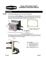
Henny Penny
CFA Pressure Fryer
Electric Model 500
Gas Model 600

Model 500/600
This manual should be retained in a convenient location for future reference.
A wiring diagram for this appliance is located on the rear shroud cover of the control panel.
Post in a prominent location, instructions to be followed if user smells gas. This information
should be obtained by consulting the local gas supplier.
The Model 600 Fryer is equipped with a continuous pilot. But Fryer cannot be operated with-
out electric power. Fryer will automatically return to normal operation when power is restored.
Do not obstruct the flow of combustion and ventilation air. Adequate clearance must be left all
around appliance for sufficient air to the combustion chamber.
To avoid a fire, keep appliance area free and clear from combustibles.
Improper installation, adjustment, alteration, service or maintenance can cause property
damage, injury or death. Read the installation, operating and maintenance
instructions thoroughly before installing or servicing this equipment.
DO NOT STORE OR USE GASOLINE OR OTHER FLAMMABLE VAPORS
AND LIQUIDS IN THE VICINITY OF THIS OR ANY OTHER APPLIANCE. FIRE OR
EXPLOSION COULD RESULT.
305 FM06-003 Revised 05-09-05

Model 500/600
TABLE OF CONTENTS
Section Page
Section 1. TROUBLESHOOTING ............................................................................................... 1-1
1-1. Introduction......................................................................................................... 1-1
1-2. Safety ................................................................................................................. 1-1
1-3. Troubleshooting ................................................................................................... 1-2
1-4. Warnings and Error Messages ............................................................................. 1-14
1-5. Diagnostic Mode Details...................................................................................... 1-16
1-6. Information Mode Details .................................................................................... 1-33
Section 2. MAINTENANCE ........................................................................................................ 2-1
2-1. Introduction......................................................................................................... 2-1
2-2. Maintenance Hints ............................................................................................... 2-1
2-3. Preventive Maintenance Schedule ........................................................................ 2-2
2-4. Removing the Control Panel................................................................................. 2-2
2-5. Transformer Replacement .................................................................................... 2-3
2-6. Temperature Probe Replacement ......................................................................... 2-4
2-7. High Temperature Limit Control (Electric and Gas Models) .................................. 2-6
2-8. Heating Elements (Electric Models)...................................................................... 2-9
2-9. Heating Contactors (Electric Models) .................................................................. 2-12
2-10. Gas Burner Assembly (Gas Models) .................................................................... 2-15
2-11. Thermocouple (Gas Models) ............................................................................... 2-18
2-12. Gas Control Valve ............................................................................................... 2-20
2-13. Electrical Components ......................................................................................... 2-23
2-14. Pressure Regulation/Exhaust ................................................................................ 2-27
2-15. Filtering System ................................................................................................... 2-47
2-16. Gas Conversion................................................................................................... 2-52
Wiring Diagrams .................................................................................................. 2-55
Section 3. PARTS INFORMATION ............................................................................................. 3-1
3-1. Introduction......................................................................................................... 3-1
3-2. Genuine Parts ...................................................................................................... 3-1
3-3. Model Variations ................................................................................................. 3-1
3-4. How to Find Parts ............................................................................................... 3-1
3-5. Subassemblies ..................................................................................................... 3-2
3-6. How to Order Parts ............................................................................................ 3-2
3-7. Prices.................................................................................................................. 3-3
3-8. Delivery .............................................................................................................. 3-3
3-9. Warranty ............................................................................................................. 3-3
3-10. Index of Parts List Illustrations ............................................................................. 3-4
i 305

Model 500/600
SECTION 1. TROUBLESHOOTING
1-1. INTRODUCTION
This section provides troubleshooting information in the form of an
easy to read table.
If a problem occurs during the first operation of a new fryer, recheck
the installation per Section 2 of the Operator’s Manual.
Before troubleshooting, always recheck the operating procedure per
Section 3 of the Operator’s Manual.
305 1-1
The Henny Penny Pressure Fryer has many safety features incorpo-
rated. However, the only way to ensure a safe operation is to fully
understand e proper installation, operation, and maintenance proce-
dures. The instructions in this manual have been prepared to aid you in
learning the proper procedures. Where information is of particular
importance or safety related, the words DANGER, WARNING,
CAUTION, and NOTICE are used. Their usage is described below.
SAFETY ALERT SYMBOL is used with DANGER,
WARNING, or CAUTION which indicates a personal injury
type hazard.
NOTICE is used to highlight especially important information.
CAUTION used without the safety alert symbol indicates
a potentially hazardous situation which, if not avoided,
may result in property damage.
CAUTION indicates a potentially hazardous situation
which, if not avoided, may result in minor or moderate
injury.
WARNING indicates a potentially hazardous situation
which, if not avoided, could result in death or serious
injury.
DANGER INDICATES AN IMMINENTLY
HAZARDOUS SITUATION WHICH, IF NOT
AVOIDED, WILL RESULT IN DEATH OR SERIOUS
INJURY.
1-2. SAFETY

Model 500/600
1-3. TROUBLESHOOTING
To isolate a malfunction, proceed as follows:
1. Clearly define the problem (or symptom) and when it occurs.
2. Locate the problem in the troubleshooting table.
3. Review all possible causes. Then, one-at-a-time work
through the list of corrections until the problem is solved.
Refer to the maintenance procedures in Section 2 of
this manual to safely and properly make the checkout
and repair needed. If maintenance procedures are not
followed correctly, injuries and/or property damage
could result.
1-2 305

Model 500/600
Problem Cause Correction
COOKING SECTION
Product Color Not
Correct:
A. Too Dark (some batches) • Temperature programmed too hot • See Diagnostic Mode D 10;
if temperature settings have
been changed, have the controls
reintialized
• Breading product too far • Bread product just before frying
in advance
• Done alarm ignored for more • If the fryer hasn’t been used
than 20 seconds since the problem batch, see
Information Mode 4 H;
for more information on
this problem, see Information
Modes 5 U, 6 U, 7 R, or 8 R
• Wrong product button pressed • Be sure to press the correct
product button; if the fryer
hasn’t been used since the
problem batch, see Information
Mode 4 B to see what product
button was pressed
B. Too Dark (all batches)
• Temperature probe out of • See Diagnostic Mode D 1
calibration to adjust color of product
• Check temperature probe cali-
bration; see Checking Tempera-
ture Probe Calibration Section;
if less than 15 degrees off, have
probe calibrated; if more than
15 degrees off, replace probe
• Peanut oil too old • If peanut oil is smoking or has
burnt taste, change peanut oil
• See Diagnostic Mode D 2;
Change peanut oil if controls
indicate it should be changed
• Peanut oil too dark • Filter peanut oil
• Change peanut oil
• Faulty probe “E6” • If probe can’t be recalibrated,
have probe replaced
305 1-3

Model 500/600
Problem Cause Correction
COOKING SECTION (Continued)
C. Too Light (all batches) • Temperature probe out of • See Diagnostic Mode D 1
calibration to adjust color of product
• Check temperature probe cali-
bration; see Checking Tempera-
ture Probe Calibration Section;
if less than 15 degrees off, have
probe calibrated; if more than
15 degrees off, replace probe
• Slow fryer heat-up/recovery • See Diagnostic Mode D 4
for present day’s performance;
or see Information Modes 5, 6,
7, 8, and 9 for more information
on this problem
• Low voltage; see Diagnostic
Mode D 3 for present day’s
voltage performance; see
Information Modes 4, 5, 6, 7, 8,
9, and 15 for more information
on this problem
• Low gas pressure; have gas
pressure checked going to
burners, on gas fryers
• Oil usage wasn’t set for new • See Diagnostic Mode D 2 for
peanut oil the age of the oil; see section
3-7 for setting the age of the oil
D. Too Light (some batches) •Temperature programmed too low • See Diagnostic Mode D 10;
if temperature settings have
been changed, without authori-
zation, have the controls
reintialized
• Product placed in peanut oil • If fryer hasn’t been used since
before proper temperature the problem batch, see Informa-
tion Mode 4 C; for more
information on this see Informa-
tion Modes 5 S, 6 S, 7 P, or 8 P
• Wrong product button pushed • If fryer hasn’t been used since
problem batch, see Information
Mode 4 B to see what product
was selected
1-4 305

Model 500/600
Problem Cause Correction
COOKING SECTION (Continued)
D. Too Light (some batches) • Cook Cycle aborted before alarm • See Diagnostic Mode D 7
(Continued) and “DONE” flashes to see how many times
the Cook Cycle was stopped
before the end of the cycle
• Frozen product placed in • Use fresh or thawed product;
peanut oil see Diagnostic Mode D 5
to see if the controls sensed any
frozen or overloaded batches
Dryness of Product
• Moisture loss prior to cooking • Use fresh product
• Cover product with plastic wrap,
reducing evaporation
• Over-cooking the product • Done alarm ignored for more
than 20 seconds; if the fryer
hasn’t been used since the
problem batch, see Information
Mode 4 H; for more informa-
tion on this problem, see Infor-
mation Modes 5 U, 6 U, 7R, or
8 R
• Time of Cook Cycle set too long • See Diagnostic Mode D 10;
if time settings have been
changed, have the controls
reintialized
• Wrong product button pushed • If fryer hasn’t been used since
problem batch, see Information
Mode 4 B to see what product
was selected
• Low operating pressure • Check pressure gauge reading
Check for pressure leaks
Burned Taste • Burned peanut oil flavor • Replace peanut oil
• Peanut oil needs filtering • Filter peanut oil more often
• Frypot not properly cleaned • Drain and clean frypot
305 1-5

Model 500/600
Problem Cause Correction
COOKING SECTION (Continued)
Product not done • Cook Cycle aborted before alarm, • See Diagnostic Mode D 7
and
“DONE” flashes to see how many times
the Cook Cycle was stopped
before the end of the cycle
• Frozen product placed in • Use fresh or thawed product;
peanut oil see Diagnostic Mode D 5
to see if the controls sensed
frozen or overloaded batches.
• Wrong product button pushed • If fryer hasn’t been used since
problem batch, see Information
Mode 4 B to see what product
was selected
• Temperature programmed too low • See Diagnostic Mode D 10;
or not programmed properly if temperature settings have
been changed, have the controls
reintialized
• Temperature probe out of • Check temperature probe cali-
calibration bration; see Checking Tempera-
ture Probe Calibration Section;
a. If less than 5
° off, see
Diagnostic Mode D 1
b. If between 5 and 15 degrees
off, calibrate probe; if more
than 15° off, replace probe
• Slow fryer heat-up/recovery • See Diagnostic Mode D 4 for
present day’s performance; or
see Information Modes 5, 6, 7, 8,
and 9 for more information on
this problem
• Low voltage; see Diagnostic
Mode D 3 for present day’s
voltage performance; see
Information Modes 4, 5, 6, 7, 8,
9, and 15 for more information
on this problem
• Low gas pressure; have gas
pressure checked going to
burners, on gas fryers
• Product too thick • Make sure chicken filets have
been fileted
1-6 305

Model 500/600
Problem Cause Correction
POWER SECTION
With COOK/PUMP Switch • Open circuit • Check to see if fryer is plugged
in COOK position, fryer is in
completely without power
• Check wall circuit breaker or
fuse
• Have a qualified service techni-
cian check power supply and
COOK/PUMP switch
PRESSURE SECTION
Pressure will not • Exhaust line from solenoid • Turn unit off and allow fryer to
exhaust at end of valve to exhaust tank cool to release pressure from
cooking cycle. clogged frypot; have all pressure lines,
exhaust stacks, and exhaust
tank cleaned
• Solenoid valve clogged • Have solenoid checked and
cleaned
Operating pressure too high
• Deadweight clogged • Turn unit off and allow fryer to
cool to release pressure from
frypot; remove deadweight and
clean, per Cleaning the Dead-
weight Valve Section.
• Exhaust line to stack clogged • Clean exhaust line to stack
DO NOT OPERATE UNIT IF PRESSURE GAUGE SHOWS HIGH PRESSURE CONDITIONS.
SEVERE INJURIES AND BURNS WILL RESULT. IMMEDIATELY PLACE THE POWER/
PUMP SWITCH IN THE OFF POSITION, WHICH RELEASES THE PRESSURE BY ALLOW-
ING THE UNIT TO COOL. DO NOT RESUME USE OF UNIT UNTIL CAUSE OF HIGH
PRESSURE HAS BEEN FOUND AND CORRECTED.
305 1-7

Model 500/600
Problem Cause Correction
PRESSURE SECTION (Continued)
Pressure does not • Not enough product in fryer • Place proper quantity of
build or product not fresh fresh product within frypot to
generate steam
• Metal shipping spacer not • Remove shipping spacer;
removed from deadweight see Unpacking Section
• Lid open or not latched • Close and latch lid
• Solenoid valve leaking or • Have solenoid valve checked or
not closing cleaned
• Deadweight assembly leaking • Have deadweight assembly
repaired
• Pressure not programmed • See Diagnostic Mode D 10;
if pressure settings have been
changed, have the controls
reintialized
• Lid gasket leaking • Reverse gasket or lid needs
adjusted
• Safety relief valve leaking. • Check and replace if necessary
FILTER SYSTEM SECTION
Filter motor runs • Pump clogged • Have pump cleaned
but pumps peanut oil
slowly • Filter line connection • Tighten all filter line
loose connections
• Solidified peanut oil • Clear all filter lines of solidified
in lines peanut oil
Filter switch on, • Defective COOK/PUMP switch • Have switch checked
motor does not run
• Defective motor • Have motor checked
• Motor thermal protector tripped • Reset thermal protector
per Filter Pump Motor
Thermal Protector Section
1-8 305

Model 500/600
Problem Cause Correction
FILTER SYSTEM SECTION (Continued)
Motor hums but • Clogged lines or pump • Have pump and lines removed
will not pump and cleaned
• Have pump seal, rotor
and rollers replaced
HEATING OF PEANUT OIL SECTION
Peanut oil will not heat • Blown fuse or tripped circuit • Reset breaker or replace fuse
breaker
• Faulty cord and plug • Check cord and plug
• Faulty PC board • Have control panel checked
• Faulty or tripped high limit “E10” • Reset high limit per Operating
Components Section; if high
limit doesn’t reset, have it
checked
• Drain valve open “E15” • Close drain valve
• Possible faulty probe “E6” • Have temperature probe
checked
• Possible faulty contactor • See Diagnostic Modes D 4;
(electric models) see if “CHECK COILS,
CONTACTORS AND
WIRING” shows on display
• Gas valve knob turned to the • Make sure the gas valve knob
OFF position (gas models) is turned to ON
• Faulty thermocouple on gas • Have thermocouple checked
control valve (gas models)
• Faulty COOK/PUMP switch • See Information Mode10
• Faulty drain switch “E15” and check to see if the
• Possible faulty gas control input code is present; if not,
have fryer checked by a
certified service technician
305 1-9
• Light pilot per Gas Pilot Lighting
Procedure section in Operator’s
Manual
• Pilot not lit (gas models)

Model 500/600
Problem Cause Correction
HEATING OF PEANUT OIL SECTION (Continued)
Peanut oil heating slowly
• Low or improper amps • See Infomation Mode 16
for present amperage; or
see Information Modes 4, 5, 6,
7, 8, 9, for more information
on this problem; Diagnostic
Mode D 4 gives present day’s
heating performance
• Low or improper voltage • See Diagnostic Modes D 3 &
D 4 for present day’s voltage
and heating performance; or
see Information Modes 4, 5, 6,
7, 8, 9, and 15 for more informa-
tion on this problem
• Weak or burnt out • See Diagnostic Modes D 4;
elements (elec. model) see if “CHECK
COILS, CONTACTORS
• Burnt or charred connectors AND WIRING” shows on
display; if so, have fryer
• Faulty contactor (electric models) checked by a certified service
technician
• Wire(s) loose • Have wires tightened
• Supply line too small - low • Increase supply line size;
gas volume (gas models) refer to installation
instructions
• Improper ventilation • Refer to installation
system (gas models) instructions
1-10 305

Model 500/600
PROBLEM CAUSE CORRECTION
PEANUT OIL DRAINING
Peanut oil will not
drain from frypot
(all models)
• Drain valve clogged with crumbs • Open valve - force cleaning
brush through drain opening
• Drain valve will not open by
turning handle
• Replace cotter pins in valve
coupling
LID SECTION
Gasket coming out
of lid liner
• Crumbs under gasket
• Remove gasket and clean per
Pressure Regulation/Exhaust section
• Clean top rim of frypot
• Replace worn or damaged
gasket per Pressure Regulation/Exhaust
section
Lid spindle will not
turn or turns hard
with lid open
• Spindle dry • Lubricate spindle per Pressure Regulation/
Exhaust section
• Worn acme nut • Replace acme nut per Pressure Regulation/
Exhaust section
305 1-11
1-3. TROUBLESHOOTING (Continued)

Model 500/600
PROBLEM CAUSE CORRECTION
Lid will not unlatch
from closed position
• Lid gasket not seated properly
or idle nut not adjusted
• To check the problem, perform
the following procedures:
LID SECTION (Continued)
1. Remove pressure from frypot.
2. Turn main switch to off
position.
3. Drain shortening from frypot.
The next procedure must be
performed while holding the
lid closed until the lid latch is
free from the crossarm. Failure
to hold down the lid will result
in the lid springing back to a
full open position. Personal injury,
or damage to the hinge may result.
4. Remove Tru-Arc ring. Drive
latch pin out. Lid will open.
5. Raise lid slowly.
6. Reinstall latch.
7. Adjust limit stop, per Pressure
Regulation/Exhaust section.
8. Lid gasket should be properly
seated in lid liner.
1-12 305
1-3. TROUBLESHOOTING (Continued)

Model 500/600
1-4. WARNINGS AND
ERROR MESSAGES
The controls monitor procedure problems and system failures with warn-
ings and error codes. The display shows the warning or error code, and
an alarm sounds.
Pressing cancels most warnings and pressing any control button
stops most Error Code alarms. But there are some exceptions (see
below). The display shows the error until the situation is corrected.
WARNINGS
DISPLAY CAUSE CORRECTION
“W-1” “LOW Incoming supply voltage too low Have voltage at plug and receptacle checked
VOLTAGE”
“W-2”
Faulty components or connections Have elements, connections, and contactors
“SLOW checked
HEAT-UP”
“W-3” Product loaded into frypot Wait until peanut oil is at proper temperature
“WAS NOT before lights before loading product
READY”
“W-4” Frozen or too much product Do not overfill or place frozen product
“SLOW in frypot into the frypot
COOKING”
“W-5” Product loaded into frypot Wait until peanut oil is at proper temperature
“SLOW before lights before loading product.
COOKING”
“W-6” Faulty components or connections Have elements, connections, and contactors
“SLOW checked
COOKING”
“W-7” Faulty components or connections Have elements, connections, and contactors
“LOW AMPS” checked
“W-9” Product overcooked (may Discard product immediately
“DISCARD appear after a “W-6”, “SLOW
PRODUCT” COOKING” warning)
“OIL TOO Didn’t allow peanut oil to drop CANCEL button will not stop this warning;
HOT” down to current product’s setpoint once the peanut oil temperature drops to set-
temperature point temperature, the alarm automatically stops
“E-4” PC board too hot Check ventilation louvers on side of fryer for
“CPU TOO obstructions; if louvers are clear, have PC
HOT” board checked; check cooling fan if present.
205 1-13

Model 500/600
1-4. WARNINGS AND
ERROR MESSAGES (Continued)
ERROR CODES
DISPLAY CAUSE CORRECTION
“E-5” Controls sensing 405°F Have heat components and temperature probe
“FRYER TOO or above checked
HOT”
“E-6”
(A or B) Faulty temperature probe or Have temperature probe and connection
“FRYER TEMP connection checked
SENSOR
FAILED”
“E-10” Peanut oil temperature too hot, Reset high limit per Operating Components;
“HIGH LIMIT drain valve opened while heat was Section; check peanut oil temperature for
TRIPPED” on, or faulty high limit overheating; have heat components checked if
high limit continues to trip
“E-15” Drain is open or faulty microswitch Close drain; have drain microswitch checked
“DRAIN IS if error code persists
OPEN”
“E-25” Wrong or faulty elements or wiring Have electrical supply, wiring, and elements
“HEAT AMPS problem. checked
WERE TOO
HIGH”
(500 fryer only) Because of the seriousness of this error code,
turn the COOK/PUMP switch OFF and back
to COOK to cancel.
“E-26” Faulty contactors or PC board Have the contactors and PC board checked
“HEAT AMPS
ARE
LOCKED ON”
(500 fryer only) This error code could be displayed even with
the COOK/PUMP switch turned OFF. Unplug
fryer or shut off the wall circuit breaker to
disconnect electrical power to fryer.
“E-41” Memory scrambled; an individual Turn the COOK/PUMP switch OFF and back
“SYSTEM product program may be scrambled; to COOK; if error code persists, have the PC
DATA LOST” ex: “E-41 -2- DATA LOST”; this board checked or re-initialized
means product #2 program is
scrambled
“E-41” Memory scrambled; an individual Turn the COOK/PUMP switch OFF and back
“SYSTEM product program may be scrambled; to COOK; if error code persists, have the PC
DATA LOST” ex: “E-41 -2- DATA LOST”; this board checked or re-initialized
means product #2 program is
scrambled
1-14 205

Model 500/600
1-4. WARNINGS AND
ERROR MESSAGES (Continued)
ERROR CODES
DISPLAY CAUSE CORRECTION
“E-41” Memory scrambled; an individual Turn the COOK/PUMP switch OFF and back
“SYSTEM product program may be scrambled; to COOK; if error code persists, have the PC
DATA LOST” ex: “E-41 -2- DATA LOST”; this board checked or re-initialized
means product #2 program is
scrambled
“E-46” Faulty eprom or PC board Turn the COOK/PUMP switch OFF and back
“DATA SAVE to COOK; if error code persists, have the PC
FAILED” board checked or re-initialized
“E-47” Failure of 12 volt DC supply Turn the COOK/PUMP switch OFF and back
“ANALOG on the I/O board to COOK; if the and DO NOT
SYSTEM
OR 12 VOLT light up when the 8888’s are displayed, have the
FAILED” I/O board replaced
Amp sensors plugged in backwards Have positions of amp sensors checked
Faulty PC board Have control panel replaced
“E-48” Failure of 12 volt DC supply Turn the COOK/PUMP switch OFF and back
INPUT on the I/O board to COOK; if the and DO NOT
SYSTEM
ERROR” light up when the 8888’s are displayed, have the
I/O board replaced
Faulty PC board Have control panel replaced
“E-70 A” Missing or broken wire in pins 1 and Have jumper wire between pins 1 and 2
“FAN VAC 2 of P11 connector, or faulty checked
JUMPER connector
MISSING”
Faulty I/O board Have I/O board checked and replaced if
necessary
“E-70 B” Faulty COOK/PUMP switch Have COOKPUMP switch checked, along
“PWR SW or switch wiring; faulty with its wiring; have I/O board checked
OR WIRES I/O board
FAILED”
“E-92” Blown 24 volt controller fuse, or Have the 14-pin cable connector checked or
“24 VOLT bad 14-pin cable connection have the fryer checked for a short to ground in
FUSE” components such as the drain switch, solenoid,
or high limit and wiring
Stuck or clogged solenoid valve Have solenoid checked and cleaned
205 1-15

Model 500/600
The Chick-fil-A fryer controllers provide diagnostic functions that let an
Operator review operating and performance data for the fryer.
The information provided by Diagnostic Mode can be used to monitor
procedural errors, such as, not waiting for the READY light before
starting a Cook Cycle, canceling cycles early, etc.
In addition, Diagnostic Mode allows slight adjustment to product color,
reports the age and accumulated wear of the oil, and reports informa-
tion about the performance of the line voltage supply.
Accessing Diagnostic Mode
To activate Diagnostic Mode, press the button, then press
button. The controller displays the following message:
“ *DIAGNOSTIC* “
“ *REPORT* “
When this introduction message is finished, the controller displays
Diagnostic step D 1 (see below).
are used to step through the report items. Press to
step forward to the next item. Press to step backward through
the report items.
The report information is grouped into sections, D 1 through D 10.
Most sections have several related items.
To toggle between English and Spanish Display Mode, press
button then press .
To exit Diagnostic Report Mode at any point, press .
1-5. DIAGNOSTIC MODE
DETAILS
1-16 305

Model 500/600
D 1: Color Adjustment
This step lets the user make slight adjustments to the product color.
The first step of this item asks
“IS PRODUCT COLOR OK?”
If product color is okay and no change is desired press or
to move on to the next item, or press to exit Diagnostic Mode.
If a change is desired, press (i.e. color is not okay). The
controller shows “ADJUST DARKNESS”, then displays the darkness
control slider:
“ LT - - - - - + - - - - - DK”
A blinking asterisk (*) indicates the current position. and
are used to adjust the darkness setting.
To make the product darker, press to move the blinking “ * “
toward the DK (darker) side.
To make the product lighter, press to move the blinking “ * “
toward the LT (lighter) side.
When done adjusting, press to exit and return to normal
operating mode.
Any temperature adjustment activated by the color adjustment feature
will be reflected in the normal setpoint display as part of the offset from
the basic product cook temperature. To view the present regulating
temperature, press twice.
In the example, “SETPT = 315°F + 6” the product cook temperature is
315°F and has an additional offset of 6°F to compensate for the age of
the oil, how long the fryer sits idle, and any color adjustments.
1-5. DIAGNOSTIC MODE
DETAILS (Continued)
305 1-17
/