Page is loading ...

1
ASKO
T7OOT7OO
T7OOT7OO
T7OO
--
--
-
SERIES DRYERSSERIES DRYERS
SERIES DRYERSSERIES DRYERS
SERIES DRYERS
SERVICE MANUALSERVICE MANUAL
SERVICE MANUALSERVICE MANUAL
SERVICE MANUAL
CONTENTSCONTENTS
CONTENTSCONTENTS
CONTENTS
Introduction and Safety RegulationsIntroduction and Safety Regulations
Introduction and Safety RegulationsIntroduction and Safety Regulations
Introduction and Safety Regulations
................
................
........
22
22
2
The Drying ProcessThe Drying Process
The Drying ProcessThe Drying Process
The Drying Process
....................................................................................
....................................................................................
..........................................
33
33
3
InstallationInstallation
InstallationInstallation
Installation
..................................................................................................................
..................................................................................................................
.........................................................
44
44
4
Dryer FeaturesDryer Features
Dryer FeaturesDryer Features
Dryer Features
..................................................................................................
..................................................................................................
.................................................
1111
1111
11
Overheat ProtectionOverheat Protection
Overheat ProtectionOverheat Protection
Overheat Protection
............................................................................
............................................................................
......................................
1212
1212
12
FF
FF
F
ault Tault T
ault Tault T
ault T
racingracing
racingracing
racing
..........................................................................................................
..........................................................................................................
.....................................................
1313
1313
13
Common ProblemsCommon Problems
Common ProblemsCommon Problems
Common Problems
......................................................................................
......................................................................................
...........................................
1414
1414
14
Components and Measurement VComponents and Measurement V
Components and Measurement VComponents and Measurement V
Components and Measurement V
aluesalues
aluesalues
alues
....
....
..
1515
1515
15
TT
TT
T
est Pest P
est Pest P
est P
rogram and Error Messagesrogram and Error Messages
rogram and Error Messagesrogram and Error Messages
rogram and Error Messages
......................
......................
...........
1818
1818
18
Consumption VConsumption V
Consumption VConsumption V
Consumption V
aluesalues
aluesalues
alues
..............................................................................
..............................................................................
.......................................
1919
1919
19
TT
TT
T
ools and Applications Areasools and Applications Areas
ools and Applications Areasools and Applications Areas
ools and Applications Areas
..........................................
..........................................
.....................
2121
2121
21
Service InformationService Information
Service InformationService Information
Service Information
..............................................................................
..............................................................................
.......................................
2323
2323
23
Appendix AAppendix A
Appendix AAppendix A
Appendix A
..................................................................................................................
..................................................................................................................
.........................................................
6262
6262
62
IndexIndex
IndexIndex
Index
........................................................................................................................................
........................................................................................................................................
....................................................................
6363
6363
63

2
You have in your hand the ASKO Service Manual for
the new generation of dryers that are friendly to the
environment in both their manufacture and use.
This new generation of dryers has been designed for
ease of servicing. By this we mean that it's a simple
job, for example, to replace a damaged side panel.
That's why we've changed the design from a one-
piece casing to a split casing.
To secure parts and wiring, we have replaced many
of the screws by plastic snap fasteners, and certain
parts have integrated ribbon cabling, all for
simplifying service.
We have also integrated service aids, such as hooks
to hang parts on, so that you can use both hands for
installation.
TT
TT
T
HE DIFFERENT MODELSHE DIFFERENT MODELS
HE DIFFERENT MODELSHE DIFFERENT MODELS
HE DIFFERENT MODELS
The table below shows the Model numbers and the
correlating model type:
Model Type
T700 TD 11 (Mechanical vented)
T720 TD 22 (Mechanical condensing)
T760 TD 33 (Electronic vented)
T780 TD 44 (Electronic condensing)
T700 is a thermostatically-controlled dryer with air
extraction. T720 is a timer-controlled dryer with a
condenser.
T760 is a sensor-controlled electronic dryer with
air extraction. T780 is a sensor-controlled electronic
dryer with a condenser.
The T760 and T780 have a humidity sensor that
can tell when the clothes are dry. On these models
you can choose from eleven languages for the LED
display.
We hope that this Service Manual will be a positive
tool in your daily work. If you have any questions
concerning servicing ASKO products, contact the
ASKO Advisory Center at:
1161 Executive Drive West
Richardson, Texas 75081
972-238-0846
INTRODUCTION AND SAFETY REGULATIONS
GENERALGENERAL
GENERALGENERAL
GENERAL
The electrical and plumbing installations should be
carried out by a qualified electrician and plumber.
Be sure to follow all Federal, State, County and local
codes.
WARNINGWARNING
WARNINGWARNING
WARNING
Always switch off the main electrical power supply
when dismantling and assembling the dryer.
WARNINGWARNING
WARNINGWARNING
WARNING
Always use a grounded EMC wristband when
working with electrical components, such as
printed circuit boards and electronic control
units.
T720 AND T780: TRANSPORT/WINTERT720 AND T780: TRANSPORT/WINTER
T720 AND T780: TRANSPORT/WINTERT720 AND T780: TRANSPORT/WINTER
T720 AND T780: TRANSPORT/WINTER
STORAGESTORAGE
STORAGESTORAGE
STORAGE
If the dryer is to be transported or stored for the
winter in unheated premises, make sure the
condensation water tank is empty.
DISPOSALDISPOSAL
DISPOSALDISPOSAL
DISPOSAL
The dryer is manufactured and labelled for recycling.
Contact your local refuge authority to find out how
the dryer should be scrapped and recycled properly.
This number is normally found in the “City of”
numbers provided in your telephone book.
WARNINGWARNING
WARNINGWARNING
WARNING
To prevent children from being accidentally
locked in the drum, the door(s) must be removed
when discarding the dryer.

3
T700 AND T760 – VENTED DRYERST700 AND T760 – VENTED DRYERS
T700 AND T760 – VENTED DRYERST700 AND T760 – VENTED DRYERS
T700 AND T760 – VENTED DRYERS
These models are vented dryers; therefore, they
required outside venting for a proper installation.
Room temperature air is heated by the heating
element and drawn into the drum, where it extracts
the dampness from the clothes. The paddles in the
drum prevent the clothes from sticking to each other.
Air passes through the lint filter in the front door,
through the exhaust system and out the exhaust vent.
On Model T700, on the way through the air
extraction system, the air passes over the thermostats.
The thermostats measures the exhaust temperature
as it leaves the dryer. When using the automatic
program, the thermostats indicate when the clothes
are dry.
On Model T760, on the way through the air
extraction system, the air passes a humidity sensor.
The sensor measures the amount of humidity in
the clothes. If you are using an automatic program,
the sensor indicates when the clothes are dry.
THE DRYING PROCESS
T720 AND T780 – CONDENSING DRYERST720 AND T780 – CONDENSING DRYERS
T720 AND T780 – CONDENSING DRYERST720 AND T780 – CONDENSING DRYERS
T720 AND T780 – CONDENSING DRYERS
These models are non-vented, condensing dryers
that are used in areas where venting is not possible.
Condenser dryers have two circulation systems: one
for drying air and one for cooling air. In the
following illustration, the black arrows show the
warm drying air, and the white arrows the cooling
air at room temperature.
1. Room temperature air
2. Air that has been heated.
3. Maist air going through the lint filter
4. Air passing the thermostats
5. Air going out the exhaust
Model T720 is a timed dryer only. The user sets
the amount of time for the dryer to run.
The drum paddles prevent the clothes from sticking
to each other. On the way through the air extraction
system, the air passes a humidity sensor.
Model T780 has a sensor that measures the amount
of humidity in the clothes. If you are using an
automatic program, the sensor indicates when the
clothes are dry.
DRYING AIRDRYING AIR
DRYING AIRDRYING AIR
DRYING AIR
Room temperature air is heated by the heating
element and passes through the drum, where it
blows through the clothes and extracts the dampness
from them.
The air is filtered through the lint filter in the front
door, goes down to the fan and onwards to the
condenser unit.
On its way through the condenser the saturated air
releases its water content. The extracted water falls
into a holder, from which it is either pumped up to
a water tank or taken out via a drain hose to a floor
drain or similar.
COOLING AIRCOOLING AIR
COOLING AIRCOOLING AIR
COOLING AIR
The condenser is cooled by air at room temperature,
drawn in through the rear of the machine. The air is
blown through the condenser and exhausts through
a grill in the bottom hatch. If the machine is built
into a cabinet, the air is drawn through the gap
between the floor and the bottom of the machine.
T700 and T760 Air Circulation
T720 and T780 Air Circulation
The black arrows
show the warm
drying air. The
white arrows
show the cooling
air at room
temperature.

4
INSTALLATION
Read these instructions carefully and completely
before you install the machine. The installation
should be carried out by a qualified service technician
who is familiar with all local codes and ordinances
for electrical and plumbing connections.
NOTE:
Cosmetic damage must be reported to the dealer
within five days from the date of purchase. After
unpacking the dryer, thoroughly check the unit for
cosmetic damage.
SPECIFICASPECIFICA
SPECIFICASPECIFICA
SPECIFICA
TIONSTIONS
TIONSTIONS
TIONS
Height 33-1/2”–34-1/2 (850–876 mm)
Width 23-7/16” (595 mm)
Plus exhaust hose connection
Depth T760/T780: 23-7/16" (595 mm)
T700/T720: 24-7/16” (620 mm)
Depth w/door open All Models: 46-1/16”
Weight T700/T760: 86 lbs (39 kg)
T720/T780: 103 lbs (47 kg)
Drum material Stainless Steel
Outer casing Stove-enamelled hot-dipped
galvanized steel with powder
coat paint or Stainless Steel
on T760 and T780
Power requirement 2800 watts
Electrical connection Stand-alone: single-phase,
208–240 V, 15 Amp
ASKO washer connected to
ASKO dryer: single-phase,
208–240 V, 30 Amp
Internal fuses (2) 15 amp.
Heating element 2500 watts
Speed 52 rpm
Drain (T720/780) 7’ 6-3/4” rubber hose
Vent hose Must be UL, CSA, or
C
UL
(not provided) approved.
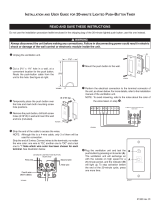
AIR EXHAUST CONNECTION (T700/T760)AIR EXHAUST CONNECTION (T700/T760)
AIR EXHAUST CONNECTION (T700/T760)AIR EXHAUST CONNECTION (T700/T760)
AIR EXHAUST CONNECTION (T700/T760)
The exhaust hose can be connected at the rear or on
either side of the dryer. When the machine is delivered,
the exhaust outlet at the rear is open. The exhaust air
hose should be routed the shortest possible way and as
straight as possible from the dryer to the formal vent
section. This will ensure proper, more efficient drying.
The dryer is shipped with a stub pipe already installed
on the rear exhaust outlet. The consumer or installer
must purchase a UL-CSA-approved exhaust hose.
The length of the vent for dryers can vary. The
general use is 22 feet of 4-inch ridged vent hose in a
straight run. Subtract 4 feet for every 90° elbow,
including any elbow at the dryer.
WARNINGWARNING
WARNINGWARNING
WARNING
To reduce the risk of fire, vented dryers must be
exhausted outdoors or the equivalent.
Exhaust Hose ConnectionExhaust Hose Connection
Exhaust Hose ConnectionExhaust Hose Connection
Exhaust Hose Connection
To connect the exhaust hose to the rear outlet,
follow the steps below:
1. Push the vent hose onto the stub pipe and secure
it with a clamp.
2. With the hose attached, insert the stub pipe into
the hole. It should snap into place.
3. After you push the dryer into place, check for
kinks in the hose. (Be careful not to use too
much hose.)
WARNINGWARNING
WARNINGWARNING
WARNING
Never cover the end of the dryer stub or vent
hose with anything to catch lint, except for a UL-
approved vent basket.
Exhaust Outlet
Stub
Clamp
Hose
(not provided)

5
INSTALLATION
CONDENSACONDENSA
CONDENSACONDENSA
CONDENSA
TION DRAIN CONNECTIONTION DRAIN CONNECTION
TION DRAIN CONNECTIONTION DRAIN CONNECTION
TION DRAIN CONNECTION
(T720/T780)(T720/T780)
(T720/T780)(T720/T780)
(T720/T780)
If possible, you should install the dryer so the
condensed water will continuously flow into a drain
or sink. To do this, follow the instructions below:
1. Disconnect the short hose (1) from the blue
nipple. (It’s okay to let the hose hang down.)
2. Connect the rubber hose supplied with the dryer
to the blue nipple (2).
3. Run the hose to a drain or sink, as illustrated.
Try to keep the hose as straight as possible.
NOTE
The drain hose must not be more than 40” (1016
mm) above the floor.
Back of dryer
40”
(1016 mm)
maximum
height
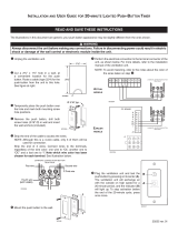
CONNECTION TCONNECTION T
CONNECTION TCONNECTION T
CONNECTION T
O A VENTILAO A VENTILA
O A VENTILAO A VENTILA
O A VENTILA
TIONTION
TIONTION
TION
DUCT (T700/T760)DUCT (T700/T760)
DUCT (T700/T760)DUCT (T700/T760)
DUCT (T700/T760)
1. Connect the exhaust hose to a ventilation
exhaust fitting or to a discharge through the wall.
2. Secure the hose joint to the outlet stub on the
machine.
3. Run the hose with as few bends and loops as
possible to the point of discharge. If necessary, it
can be extended to a maximum of 22 feet (6600
mm) of 4” (100 mm) diameter ridged hose.
Make any bends as gentle as possible. A maximum
of four 90° bends may be fitted in the hose. The
more bends and the longer the hose, the less air will
circulate through the machine, which will impede
drying performance. Subtract 4 feet (1200 mm) for
every 90° elbow.
If more than 22 feet of hose is needed, the diameter
must be increased to 6” or 8” (152 mm or 203 mm).
If the hose is taken to a wall outlet, a ventilation grill
should be fitted to prevent reverse flow of cold air.
WARNING!WARNING!
WARNING!WARNING!
WARNING!
This appliance should never be exhausted into a
chimney, a wall, a ceiling, or a concealed space of
a building. Only a metal ventilation grill should
be used.
Subtract 4 feet
(1200 mm) for
every 90° elbow.
Make sure nothing is blocking the ventilation grill.
Fit the ventilation grill to the
outside or inside of the wall.
Ventilation grill

6
INSTALLATION
FREESTFREEST
FREESTFREEST
FREEST
ANDING INSTANDING INST
ANDING INSTANDING INST
ANDING INST
ALLAALLA
ALLAALLA
ALLA
TIONTION
TIONTION
TION
The dryer can be placed next to the washing machine.
There should be at least 1/2” (12.5 mm) of space
between the washer and dryer.
It is essential that the machine is level and the
locknuts are tight to eliminate vibration.
When installing the dryer next to a wall, be sure to
leave at least 1/2” (12.5 mm) of space between the
unit and the wall. This allows for door swing of
dryer. Never push the washer flush against the wall
because it may damage the machine casing or the wall.
All hole measurements are
to the center of the holes.
NOTE
Do not raise the dryer higher than 34-1/2”.
BUILBUIL
BUILBUIL
BUIL
TT
TT
T
-IN INST-IN INST
-IN INST-IN INST
-IN INST
ALLAALLA
ALLAALLA
ALLA
TION (T700/T760)TION (T700/T760)
TION (T700/T760)TION (T700/T760)
TION (T700/T760)
Models T700 and T760 can be installed beneath a
cabinet or worktop with a minimum height of 34”
(864 mm). There must be a gap of about 1/4” (.64
mm) all around the machine, including between the
rear edge of the machine top panel and the back wall.
The opening width must be at least 24” (610 mm).
Space must also be available for the exhaust hose on
the left, right or rear of the machine. See the diagram
for hole sizes and positions. Note that the hole
measurements are to the center of the hole.
When installing the
dryer next to a wall, be
sure to leave at least
1/2” of space between
the unit and the wall.

7
INSTALLATION
STST
STST
ST
ACKED INSTACKED INST
ACKED INSTACKED INST
ACKED INST
ALLAALLA
ALLAALLA
ALLA
TIONTION
TIONTION
TION
ASKO dryers can be mounted on top of any
matching ASKO washer. Mounts are supplied with
the machine.
To install the dryer on top of the washer, follow the
steps below:
1. Remove the two outside screws (20 torx) from
the back of the washer that holds the top in
position and use them to secure the metal
brackets, as illustrated.
2. To ensure the dryer is correctly positioned on
top of the washer, align the plastic cups with
the front top edge of the washer.
To position the plastic cups, break off the left
tab (A) on the cup to be placed on the right
side of the washer and break off the right tab
(B) on the cup to be placed on the left side of
the washer. Put the cup in place before removing
the protective paper to get a general area where
the cups will be placed.
4. Once the cups are in place, break off the
remaining plastic tabs.
5. Lift the dryer into
position. Raising the
front edge, push the
dryer backwards until
it engages with the
brackets on the back
of the washer.
6. Carefully lower the
front of the dryer,
making sure the feet fit
into the plastic cups.
Tumble dryer
Washer
Stacked InstallationStacked Installation
Stacked InstallationStacked Installation
Stacked Installation
WARNING!WARNING!
WARNING!WARNING!
WARNING!
Never stack a washer on top of a dryer!
Total height 67”.
Adjustable to 69”.
Plastic cups
Washer
back
Metal brackets
Two metal brackets for
securing the dryer to
the washer
Two plastic cups to
secure the dryer legs.
3. Remove the protective
paper from the self-
adhesive surface beneath
the cups. Being careful
not to press the adhesive
surface against the top
of the washing machine,
use the tabs to position the cups (as illustrated)
then press them firmly into place.

8
INSTALLATION
Connecting a ThreeConnecting a Three
Connecting a ThreeConnecting a Three
Connecting a Three
-wire P-wire P
-wire P-wire P
-wire P
ower Cordower Cord
ower Cordower Cord
ower Cord
ELECTRICAL CONNECTIONSELECTRICAL CONNECTIONS
ELECTRICAL CONNECTIONSELECTRICAL CONNECTIONS
ELECTRICAL CONNECTIONS
The power supply cord must be grounded. If the
machine is to be used in a wet area, the supply must
be protected by a residual current device.
Connection to a permanently wired supply point
must be made only by a qualified electrician.
As supplied: Single-phase, 208–240 V, 60 Hz,
2800 Watt total rating
2500 Watt heater rating
NOTE:NOTE:
NOTE:NOTE:
NOTE:
In Canada, the dryer is delivered ready-fitted with a
four-prong plug intended for connection to a single-
phase supply.
WARNING:
The receptacle on the rear of the machine is
designed to accommodate ASKO washers ONLY
(rated 208–240 V.) To use this receptacle, you
must use the ready-fitted plug supplied with the
washing machine or an equivalent. The supply
connection must be 208–240 V, 20 A.
ASKO washers rated 208–240 V have two internal
fuses of 15 A each.
Remove cover to
access terminal box.
(Requires a 20-Torx
screwdriver.)
WARNING!WARNING!
WARNING!WARNING!
WARNING!
Before starting this procedure, be sure the power
is turned off at the breaker/fuse box.
Power Supply Cord
You will need a three-wire power supply cord with
three No. 10 copper wires and a matching three-
wire receptacle of NEMA Type 10-30R, as illustrated
below:
1. Turn the power off at the breaker/fuse box.
2. Remove terminal block cover (20 torx).
3. Assemble 3/4”
UL-listed strain
relief into the
hole below the
terminal block
opening.
4. Loosen or
remove center
terminal block
screw.
5. Connect neutral
wire (white ) of
power supply
cord to the
center, silver-
colored terminal
screw. Tighten screw.
6. Connect the other wires to outer screws.
7. Tighten the strain relief screws.
8. Replace terminal box cover on back of dryer.
9. Plug dryer into wall receptacle.
10.Turn power on at breaker/fuse box.
11.Turn on the main power switch on the dryer.
(The power indicator light should come on.)

9
INSTALLATION
Connecting a FourConnecting a Four
Connecting a FourConnecting a Four
Connecting a Four
-wire P-wire P
-wire P-wire P
-wire P
ower Cordower Cord
ower Cordower Cord
ower Cord
WARNING!WARNING!
WARNING!WARNING!
WARNING!
Before starting this procedure, be sure the power
is turned off at the breaker/fuse box.
Power Supply Cord
You will need a four-wire power supply cord with
four No. 10 copper wires and a matching four-wire
receptacle of NEMA Type 14-30R, as illustrated
below. The fourth wire must be identified with a
green cover and the neutral conductor by a white
cover.
1. Turn the power off at the breaker/fuse box.
2. Remove terminal block cover.
3. Assemble 3/4” UL-listed strain relief into the
hole below the terminal block opening.
4. Remove center terminal block screw.
5. Remove ground
wire (green with
yellow stripes)
from external
ground connector
screw. Fasten under
center, silver-
colored terminal
block screw.
6. Connect ground
wire (green) of
cord to external
ground conductor
screw.
7. Connect neutral wire (white) of cord under
center screw of terminal block.
8. Connect the other wires to outer screws.
9. Tighten the strain relief screws.
10.Replace terminal box cover on back of dryer.
11. Plug dryer into wall receptacle.
12.Turn power on at breaker/fuse box.
13.Turn on the main power switch on the dryer.
(The power indicator light should come on.)

10
INSTALLATION
REVERSING THE DOOR HINGESREVERSING THE DOOR HINGES
REVERSING THE DOOR HINGESREVERSING THE DOOR HINGES
REVERSING THE DOOR HINGES
The door hinges on ASKO dryers are reversible. The
dryers are shipped left-hinged. To reverse them,
follow the steps below:
WARNING!WARNING!
WARNING!WARNING!
WARNING!
Switch off the main power supply before you start
this procedure.
3. Pull the door out and to the left
as you turn the hinge counter
clockwise.
4. Remove the top hinge pin
then turn the hinge upside
down and put the hinge
pin into the top hole.
1. Remove the lower cover
by first removing the
two screws (A) at the
bottom of the machine.
Next, grasp the sides and pull it forward and
down.
2. Remove the
three screws
holding the
hinge.
5. Repeat steps 1–4 for the bottom hinge.
8. Remove the cover
plate by pushing it
down then lifting it
out from the top.
7. Remove the door
latch by pushing it
up then lifting it
out from the
bottom.
9. Reverse steps 6 and 7 to place the door latch
and cover plate into their new positions.
10.Tighten the screws on the sides of the doors to
hold the latch and cover plate in place.
12.Remove the screw in the top
right corner of the lower cover,
as indicated in the illustration.
(If you have a condenser dryer,
you will need to open the
condenser container door.)
13.Now you are ready to mount the door on the
right side. Holding the door at an angle (as
illustrated), fit the hinge pin into the top hole.
11.Using a flathead screwdriver,
remove the plastic plugs in the
upper and lower edge of the door
and place them in the empty
holes on the opposite side.
14.Tighten the screws in the
order illustrated at right (a, b,
c).
15.Replace the screw you
removed in step 12 (d).
16.Replace the lower cover (see Step 1 on this
page).
6. Loosen the two screws on both sides of the door
so you can remove the magnetic door latch and
the cover plate.

11
DRYER FEATURES
FRONT VIEWFRONT VIEW
FRONT VIEWFRONT VIEW
FRONT VIEW
REAR VIEWREAR VIEW
REAR VIEWREAR VIEW
REAR VIEW
Condensed water
container
(T720 & T780)
Control
panel
Bottom
cover
Lint filter
Lint filter
cover
Reversible
door
Front
panel
Side
panel
Top
cover
Condensed
water drain
hose (T720
and T780)
Reset
button
NOTE: Canadian dryers
are equipped with an
electrical cord.
Terminal
box
Receptacle for
ASKO washer

12
OVERHEAOVERHEA
OVERHEAOVERHEA
OVERHEA
T PROT PRO
T PROT PRO
T PRO
TECTIONTECTION
TECTIONTECTION
TECTION
ASKO dryers are designed with an overheat
protection switch that automatically turns off the
machine if the temperature is too high. This could
happen if the lint filter or exhaust hose becomes
clogged with dust.
Should the machine turn itself off because of
overheating, first make sure the following parts are
clean and free of lint and dirt:
• lint filter and filter cover
• exhaust hose, exhaust vent and hose
• fan housing and fan
If none of these are the problem, check the
following:
• Check both 15 Amp fuses on the back of the
dryer
• Be sure the switch actuator is making contact
with the Start switch.
• On models T760 and T780 make sure a program
(P1–P4) has been chosen.
• Check for a control unit fault
• Check for a heating element fault
NOTE:
If the dryer overheats frequently, it may not be
vented properly or the room in which it is located
may not have sufficient air circulation.
Press the reset
button to start the
machine. You should
hear a click when
the reset button is
depressed.
OVERHEAT PROTECTION
If the overheat protection switch is activated, you
have to reset it before the machine will run. To do
this, press the reset button (rubber disk) on the back
of the machine, as illustrated to the right. You should
hear a click when it engages. The machine will not
start until it has cooled sufficiently.

13
FAULT TRACING
The machine won’t start.The machine won’t start.
The machine won’t start.The machine won’t start.
The machine won’t start.
1. Make sure the power is turned on. (The indicator
light should glow red.)
2. Check that you set the program or time correctly.
3. Make sure the door is closed securely.
4. On Models T720/T780, make sure the
condenser tank is empty.
5. Check that the electric plug is securely in the
socket.
6. Check the house breaker/fuses.
7. If all of the above options are eliminated, the
overheat protection has probably been activated.
(See page 12.)
The machine starts but it stops when IThe machine starts but it stops when I
The machine starts but it stops when IThe machine starts but it stops when I
The machine starts but it stops when I
release the Start button.release the Start button.
release the Start button.release the Start button.
release the Start button.
1. The overheat protection has probably tripped.
Clean the lint filter and let the machine cool
down before trying again. (See page 12.)
The machine takThe machine tak
The machine takThe machine tak
The machine tak
es too long to dryes too long to dry
es too long to dryes too long to dry
es too long to dry
..
..
.
1. Make sure the dryer is installed according to the
instructions on pages 4–10.
2. Check that the lint filter is clean.
3. If dryer sheets are being used (not
recommended), the lint filter may need to be
washed with warm water and a soft brush to
clean any blocked holes.
4. The dryer may be overloaded, not allowing
sufficient room for the warm air to circulate
properly or the clothes to tumble freely.
5. The laundry should only be damp when it comes
out of the washer. If it seems too wet, it should
be spun in the washer at a faster or longer spin
cycle.
6. Make sure the outside vent exhaust is not
blocked.
7. On models T720/T780, make sure the
condenser is not blocked with dust or lint.
The clothes are coming out wrinkled.The clothes are coming out wrinkled.
The clothes are coming out wrinkled.The clothes are coming out wrinkled.
The clothes are coming out wrinkled.
1. The clothes should be removed as soon as the
dryer signals the end of the cycle. If it isn’t
possible to remove the clothes right away, use
the Anti-crease option.
2. Heavy fabrics and light fabrics should be dried
separately.
3. Dry only permanent press items together.
4. Dry in smaller loads.
5. Use slower spin speeds.
6. Use fabric softener in the rinse program.
7. Try using a lower wash temperature, especially
for permanent press and delicate items.
8. Make sure the customer is using the correct
temperature for the type(s) of fabric being dried.
The motor is running but the drum isn’tThe motor is running but the drum isn’t
The motor is running but the drum isn’tThe motor is running but the drum isn’t
The motor is running but the drum isn’t
turning.turning.
turning.turning.
turning.
1. The drive belt could be broken.
2. The drive belt may be dislodged from the motor
pulley.
3. The drive belt may be off the idler pulley.
4. Be sure nothing is preventing the drum from
turning.
The machine makes a funny noise.The machine makes a funny noise.
The machine makes a funny noise.The machine makes a funny noise.
The machine makes a funny noise.
1. A slight rumbling may be heard when you first
turn on the dryer. This is normal and it should
only last a few seconds.
2. Make sure the customer wasn’t drying tennis
shoes or something heavy when the noise was
heard.
3. Snaps, zippers and buttons can hit the side of
the drum and cause some noise.
ERROR MESSAGESERROR MESSAGES
ERROR MESSAGESERROR MESSAGES
ERROR MESSAGES
On Models T760 and T780, the LED window
displays an error message if a fault occurs during the
time the program is running. These error messages
are listed on page 18.

14
The washing will not dryThe washing will not dry
The washing will not dryThe washing will not dry
The washing will not dry
..
..
.
The machine only runs for 20 minutes.The machine only runs for 20 minutes.
The machine only runs for 20 minutes.The machine only runs for 20 minutes.
The machine only runs for 20 minutes.
1. Check the main power fuse.
2. Make sure the dryer wasn’t overheated due to
lint blocking the filter, condenser unit or fan
housing.
3. Model T780: Overfilling. (The display shows
"Fault indication, filling.")
4. Possibly, the machine did not reach the measured
value of 1.8 mV within 15 minutes. This could
be due to:
a. Incorrect connection to single phase – too
low heating element power (720 or 600 W)
b. Incorrect connection of element to control
unit
c. Incorrect connection in element terminal
block
d. Humidity sensor not located in fan housing
e. Faulty humidity sensor
f. Heating element open circuit
5. Check the drive belt for the following:
a. Improperly located on the motor pulley.
b. Improperly located on idler pulley.
c. Twisted.
Overheat protection tripped even thoughOverheat protection tripped even though
Overheat protection tripped even thoughOverheat protection tripped even though
Overheat protection tripped even though
lint filter and condenser unit have beenlint filter and condenser unit have been
lint filter and condenser unit have beenlint filter and condenser unit have been
lint filter and condenser unit have been
cleaned.cleaned.
cleaned.cleaned.
cleaned.
1. Check for lint in the internal fan wheel.
2. Clean the air ducts and behind the element.
3. Check for a fault in the control unit
Overfilling fault indication, even thoughOverfilling fault indication, even though
Overfilling fault indication, even thoughOverfilling fault indication, even though
Overfilling fault indication, even though
tank is emptytank is empty
tank is emptytank is empty
tank is empty
..
..
.
Condenser water pump could be blocked or burned
out. If the pump is burned out, an associated fault
will be burned wiring in the control unit. Always
check first if the condenser water pump has burned
out before installing a new control unit.
The machine shows the maximum programThe machine shows the maximum program
The machine shows the maximum programThe machine shows the maximum program
The machine shows the maximum program
time fault indication.time fault indication.
time fault indication.time fault indication.
time fault indication.
This indicates that the machine has been running
for the maximum time that the control unit is
allowed (> 3 hours) .
Several things could cause this. (It could be one of
these items or a combination.)
1. Check the main power fuse.
2. Make sure the dryer wasn’t overheated due to
lint blocking the filter, condenser unit or fan
housing.
3. Make sure the dryer isn’t incorrect connected to
a single phase, 15A.
4. Check that the external air isn’t restricted or
blocked, resulting in poor condensation.
5. A high ambient temperature + low heating
element power + low drying temperature could
result in poor condensation.
6. A low ambient temperature + low heating
element power + low drying temperature makes
it difficult to get the dampness out of the
clothes.
7. It’s possible the washing was spun dry at low
speed (i.e., less than 800 rpm), which would
make it difficult to dry the washing.
8. The washing possibly was taken out before the
program was complete and the machine was
loaded with a new batch of washing. In this case,
the control unit probably would not have time
to reset itself and the remaining program time
was added to the next drying cycle.
9. Check the humidity sensor, its wiring and
connections.
COMMON PROBLEMS

15
MOTOR (2/118/JU) 50 HZMOTOR (2/118/JU) 50 HZ
MOTOR (2/118/JU) 50 HZMOTOR (2/118/JU) 50 HZ
MOTOR (2/118/JU) 50 HZ
Part number: 80 618 24
Main winding: 23,8 Ω
Auxiliary-winding: 28,1 Ω
Voltage: 220/240 V
Current: 1,1 A, 270 W, 2850 rpm
The two-pole motor is connected directly to the
fan for internal air and via a gear to drive the drum.
On machines with condensers (T720/780) it also
drives the fan for external air.
CAPCAP
CAPCAP
CAP
ACITACIT
ACITACIT
ACIT
OROR
OROR
OR
Part number: 80 542 68
The capacitor is located on the motor and has a
value of 8µF.
CONDENSED WCONDENSED W
CONDENSED WCONDENSED W
CONDENSED W
AA
AA
A
TER PUMP (T720/T780)TER PUMP (T720/T780)
TER PUMP (T720/T780)TER PUMP (T720/T780)
TER PUMP (T720/T780)
Hanning 25WHanning 25W
Hanning 25WHanning 25W
Hanning 25W
Part number: 80 638 09
Resistance: 111 Ω
The condensation water pump pumps the water
from the condenser housing at the rear of the machine
to the water tank.
RADIO INTERFERENCE FILRADIO INTERFERENCE FIL
RADIO INTERFERENCE FILRADIO INTERFERENCE FIL
RADIO INTERFERENCE FIL
TERTER
TERTER
TER
Part number: 80 585 58
Leakage current: 230 V/ 50 Hz 0.315 mA
The filter eliminates radio interference generated by
the machine.
INDICAINDICA
INDICAINDICA
INDICA
TOR LAMPTOR LAMP
TOR LAMPTOR LAMP
TOR LAMP
Part number: 80 070 73
Current: 1.68 mA, 230 V, 50 Hz
The lamp indicates that the main power switch is
set to on.
THERMISTOR (T760/T780)THERMISTOR (T760/T780)
THERMISTOR (T760/T780)THERMISTOR (T760/T780)
THERMISTOR (T760/T780)
Part number: 80 619 00
Resistance: 40-60 kΩ at 20°-30°C
The thermistor controls temperature regulation. If the
thermistor becomes short-circuited or disconnected
from the control unit, the program stops.
CONTCONT
CONTCONT
CONT
ACTACT
ACTACT
ACT
OROR
OROR
OR
Part number: 80 091 48
Resistance: 2 kΩ
The contactor opens in case of overheating, when
the door is opened and at the end of the program.
THERMOSTTHERMOST
THERMOSTTHERMOST
THERMOST
AA
AA
A
TSTS
TSTS
TS
T700T700
T700T700
T700
Part number:
Low 80 619 46 (111° F/44°C)
Normal 80 014 45 (127° F/53°C)
Overheat 80 088 07 (239° F/115° C)
The thermostats are located in the fan housing. It
controls the temperatures for the automatic
programs and the time program up to 60 minutes.
The 239° F thermostat automatically disconnects
one of the heating loops if the temperature rises too
high. This thermostat is located next to the heating
element at the rear of the dryer.
T720T720
T720T720
T720
Part number:
Low 80 144 44 (118° F/47° C)
Normal 80 560 29 (158° F/70° C)
This thermostat is located in the fan housing. It
controls the temperature for the automatic programs
and the time program up to 60 min.
OVERHEAOVERHEA
OVERHEAOVERHEA
OVERHEA
T PROT PRO
T PROT PRO
T PRO
TECTION THERMOSTTECTION THERMOST
TECTION THERMOSTTECTION THERMOST
TECTION THERMOST
AA
AA
A
TT
TT
T
Part number: 80 084 87 (302° F/150°C
manual)
This thermostat stops the program if the
temperature rises too high. The unit has to be
manually reset. It is located next to the heating
element at the rear of the dryer.
HUMIDITY SENSOR (T760/T780)HUMIDITY SENSOR (T760/T780)
HUMIDITY SENSOR (T760/T780)HUMIDITY SENSOR (T760/T780)
HUMIDITY SENSOR (T760/T780)
Part number: 80 618 55
The humidity sensor is used to control the drying
process. During operation the sensor output signal
is between 1 and 16 mV DC. Any other value causes
the program to stop.
OVERFILL PROTECTION (T720/780)OVERFILL PROTECTION (T720/780)
OVERFILL PROTECTION (T720/780)OVERFILL PROTECTION (T720/780)
OVERFILL PROTECTION (T720/780)
Part number: 80 526 43
If both of the dryer containers are overfilled, the
program is stopped by a switch in the lower
container. The LED window indicates overfilling.
COMPONENTS AND MEASUREMENT VALUES

16
39
40
41
42
43
53
54
55
56
57
1+2
1
1+2
1
1+2
1
OFF
11
1
OFF
OFF1+2
1+2
1
1+2
1
1+2
1
OFF
21
2
OFF
OFF1+2
Low Temperature
Normal Temperature
1 = High Power Heater
2 = Low Power Heater
Temperature ˚C
ELECTRICAL CONNECTIONSELECTRICAL CONNECTIONS
ELECTRICAL CONNECTIONSELECTRICAL CONNECTIONS
ELECTRICAL CONNECTIONS
(See pages 8 and 9.)
DOOR SWITCHDOOR SWITCH
DOOR SWITCHDOOR SWITCH
DOOR SWITCH
Part number: 50 531 07
The door operates a door switch. When the door is
opened, the program stops. If the door is opened
and closed during the program, the machine must
be restarted with the Start button.
BUZZER (T700/T720)BUZZER (T700/T720)
BUZZER (T700/T720)BUZZER (T700/T720)
BUZZER (T700/T720)
Part number: 80 618 83
The buzzer sounds to indicate that the program has
finished.
COMPONENTS AND MEASUREMENT VALUES
PROGRAM CONTROL UNIT (T760/T780)PROGRAM CONTROL UNIT (T760/T780)
PROGRAM CONTROL UNIT (T760/T780)PROGRAM CONTROL UNIT (T760/T780)
PROGRAM CONTROL UNIT (T760/T780)
The control unit contains microprocessors to control
the program, motor, heating element etc.
LED WINDOW LED WINDOW
LED WINDOW LED WINDOW
LED WINDOW
(T760/T780) (T760/T780)
(T760/T780) (T760/T780)
(T760/T780)
The LED window displays selected programs and
options and program information. (See page xx.)
PROGRAMMER (T700/T720)PROGRAMMER (T700/T720)
PROGRAMMER (T700/T720)PROGRAMMER (T700/T720)
PROGRAMMER (T700/T720)
The programmer has mechanical setting points and
a motor with four-minute steps.
HEAHEA
HEAHEA
HEA
TING SEQUENCE FOR MODELS T700 AND T760TING SEQUENCE FOR MODELS T700 AND T760
TING SEQUENCE FOR MODELS T700 AND T760TING SEQUENCE FOR MODELS T700 AND T760
TING SEQUENCE FOR MODELS T700 AND T760

17
COMPONENTS AND MEASUREMENT VALUES
46
47
48
49
50
69
(64)
70
(65)
71
(66)
72
(67)
73
(68)
1+2
1
1+2
1
1+2
1
OFF
11
1
OFF
OFF1+2
1+2
1
1+2
1
1+2
1
OFF
21
2
OFF
OFF1+2
Low Temperature
Normal Temperature
1 = High Power Heater
2 = Low Power Heater
Temperature ˚C
HEAHEA
HEAHEA
HEA
TING ELEMENTTING ELEMENT
TING ELEMENTTING ELEMENT
TING ELEMENT
T700/T760 – 2620 WT700/T760 – 2620 W
T700/T760 – 2620 WT700/T760 – 2620 W
T700/T760 – 2620 W
Part number: 80 618 33
Resistance: 66.7/25.7 Ω
The element has a maximum power rating of
2620W but consists of two loops of 1900W and
720W, which permits rewiring from 2620W to
1900W.
HEAHEA
HEAHEA
HEA
TING SEQUENCE FOR MODELS T720 AND T780TING SEQUENCE FOR MODELS T720 AND T780
TING SEQUENCE FOR MODELS T720 AND T780TING SEQUENCE FOR MODELS T720 AND T780
TING SEQUENCE FOR MODELS T720 AND T780
T720/T780 – 2500 WT720/T780 – 2500 W
T720/T780 – 2500 WT720/T780 – 2500 W
T720/T780 – 2500 W
Part number: 80 637 71
Resistance: 79,7/25 Ω
The element has a maximum power rating of
2500W but consists of two loops of 1900 W and
600 W, which permit rewiring from 2500W to
1900W.

18
TEST PROGRAMTEST PROGRAM
TEST PROGRAMTEST PROGRAM
TEST PROGRAM
The machine must be in its starting state (obtained
by pressing the main power button).
Short-circuit the outputs ST4-1 and ST4-2.
Start the test program.
T780: Start the condensation water
pump.
or wait for 60 seconds and the test
program will continue.
The program heats, increasing the temperature by
57° F (14° C) in a maximum of 10 minutes, then
allows it to cool for 5 minutes (testing that the
heating element is working).
The value detected by the humidity sensor can vary
according to the environment and on whether there
is wet clothing in the dryer.
ERROR MESSAGES – T760/T780ERROR MESSAGES – T760/T780
ERROR MESSAGES – T760/T780ERROR MESSAGES – T760/T780
ERROR MESSAGES – T760/T780
Error messages will display in the LED window if a
fault occurs while a program is in progress. The table
below defines each possible error message. Once the
problem is resolved you may have to turn the power
off then on to clear the error message.
Message: Three hoursMessage: Three hours
Message: Three hoursMessage: Three hours
Message: Three hours
The machine has run the maximum drying time
(three hours).
Possible solutions:
• Make sure both fuses are intact.
• Clean the lint filter.
• Make sure exhaust hose is clear (T760).
• Make sure the condenser (T780) is clear of lint
and dust.
• Clear message by turning the power off then on.
TEST PROGRAM AND ERROR MESSAGES
Message: Overflow (T780)Message: Overflow (T780)
Message: Overflow (T780)Message: Overflow (T780)
Message: Overflow (T780)
The condensed water container is full. This container
is located at the top left corner of the dryer.
Possible solutions:
• Make sure the condensed water container is
empty. If draining into a drain pipe, make sure
the black rubber hose is not kinked or blocked.
The drain should not be higher than 40 inches
(1016 mm) from the floor.
• Make sure the condensation pump is not
blocked.
Message: SensorMessage: Sensor
Message: SensorMessage: Sensor
Message: Sensor
This can appear if there are dry clothes in the drum
when the unit is started or if the humidity sensor is
not installed properly in the fan housing or control
unit. In this case, the machine will stop after 20 minutes.
It could also be caused by a fault in the humidity
sensor. If the message does not disappear when you
open the door, check the humidity sensor.
Message: ThermistorMessage: Thermistor
Message: ThermistorMessage: Thermistor
Message: Thermistor
The thermistor may have become disconnected or
have an internal fault. A serviceable thermistor has a
resistance of between 60 and 40 kW at 68° F–86° F
(20° C–30° C).
Possible causes and solutions:
• The thermistor is not properly installed in the
fan housing. In this case, the heating element
will remain switched in for as long as the
thermistor cannot detect the selected air
temperature. This can lead to an excessively high
air temperature in the drum.
• The filter could be blocked. In this case, the
overheat protection device is tripped and the
machine will stop. Once the unit is cool, press
the reset button on the rear of the machine to
start the machine.
• The incoming phase is missing.
– Error L1 – the machine will stop after 20
minutes. Low heating element power (720
or 600 W).
– Error L2 – the machine will not start.
Indicator lamp not lit.
– Error L3 – the machine operates but the
running time is too long (low heating
element power (1900W)).
• The fan motor stops after a few seconds.
Overheat protection trips, heating element and
control damaged.
Start
P1
P2
Amplified voltage value
from humidity sensor
Temperature measured
by thermistor

19
CONSUMPTION VALUES
T700/T720T700/T720
T700/T720T700/T720
T700/T720
Before tumble drying, cotton garments should be
spun at 800 to 1600 rpm (long spin drying) in an
ASKO washer. Other garments (non-iron and
acrylic) should be spun at 800 rpm (short spin
drying) in an ASKO washer.
The following conditions apply for the consumption
values stated below:
Incoming air temperature: 68° F (20° C)
Incoming air humidity: 65%
Drying temperature: Normal ( )
Low ( )
Heating element power: T700 2620W
T720 2500W
T700 CONSUMPTION VALUEST700 CONSUMPTION VALUES
T700 CONSUMPTION VALUEST700 CONSUMPTION VALUES
T700 CONSUMPTION VALUES
*Approximate number of pounds for each load size: Full = 11 pounds; Half = 5.5 pounds
** kWh values are based on 800 – 1600 rpm spins.
ENERGY
LOAD CONSUMPTION
PROGRAM FABRIC TEMP SIZE * (approx. kWh) **
1. Extra dry Cotton, linen Normal Full 3.8 – 3.3
2. Normal Dry Cotton, linen Normal Full 3.4 – 2.6
Permanent press, cotton/polyester Low Half 1.3 –
Acrylics, rayon, acetates Low Half 1.7
T720 CONSUMPTION VALUEST720 CONSUMPTION VALUES
T720 CONSUMPTION VALUEST720 CONSUMPTION VALUES
T720 CONSUMPTION VALUES
*Approximate number of pounds for each load size: Full = 11 pounds; Half = 5.5 pounds
** kWh values are based on 800 – 1600 rpm spins.
ENERGY
LOAD CONSUMPTION
FABRIC SIZE * ( approx. kWh) **
Cotton, linen Full 3.1 – 2.4
Permanent press, cotton/polyester Half 1.2 –
Acrylics, rayon, acetates Full 1.7 –

20
T760T760
T760T760
T760
Before tumble drying, cotton garments should be
spun at 800 to 1600 rpm (long spin drying) in an
ASKO washer. Other garments (non-iron and
acrylic) should be spun at 800 rpm (short spin
drying) in an ASKO washer.
CONSUMPTION VALUES
T760 CONSUMPTION VALUEST760 CONSUMPTION VALUES
T760 CONSUMPTION VALUEST760 CONSUMPTION VALUES
T760 CONSUMPTION VALUES
*Approximate number of pounds for each load size: Full = 11 pounds; Half = 5.5 pounds
** kWh values are based on 800 – 1600 rpm spins.
The following conditions apply for the consumption
values stated below:
Incoming air temperature: 68° F (20° C)
Incoming air humidity: 65%
Drying temperature: Normal ( )
Low ( )
Heating element power: 2620 W
T780T780
T780T780
T780
Before tumble drying, cotton garments should be
spun at 800 to 1600 rpm (long spin drying) in an
ASKO washer . Other garments (non-iron and
acrylic) should be spun at 800 rpm (short spin
drying) in an ASKO washer.
The following conditions apply for the consumption
values stated below:
Incoming air temperature: 68° F (20° C)
Incoming air humidity: 65%
Drying temperature: Normal ( )
Low ( )
Heating element power: 2500 W
T780 CONSUMPTION VALUEST780 CONSUMPTION VALUES
T780 CONSUMPTION VALUEST780 CONSUMPTION VALUES
T780 CONSUMPTION VALUES
*Approximate number of pounds for each load size: Full = 11 pounds; Half = 5.5 pounds
** kWh values are based on 800 – 1600 rpm spins.
ENERGY
LOAD CONSUMPTION
PROGRAM FABRIC TEMP SIZE * (kWh) **
P1 Extra dry Cotton, linen Normal Full 4.1 – 3.4
P2 Dry Cotton, linen Normal Full 3.9 – 3.1
Permanent press, cotton/polyester Low Half 1.7 –
P3 Normal dry Cotton, linen Normal Full 3.4 – 2.6
Permanent press, cotton/polyester Low Half 1.5 –
Acrylics, rayon, acetates Low Half 1.7 –
P4 Iron dry Cotton, linen Normal Full 2.4 – 2.0
ENERGY
LOAD CONSUMPTION
PROGRAM FABRIC TEMP SIZE * (kWh) **
P1 Extra dry Cotton, linen Normal Full 3.8 – 3.1
P2 Dry Cotton, linen Normal Full 3.5 – 2.8
Permanent press, cotton/polyester Low Half 1.4 –
P3 Normal dry Cotton, linen Normal Full 3.4 – 2.6
Permanent press, cotton/polyester Low Half 1.5 –
Acrylics, rayon, acetates Low Half 1.7 –
P4 Iron dry Cotton, linen Normal Full 2.4 – 2.0
/