Page is loading ...

04723999_01.eps
Multi-Gas Monitor
Technical Manual
Dräger X-am
®
5000
approved as type MQG 0010
Visit: www.thesafetyequipmentstore.com or [email protected] for sales and service.

2
Content
Content
For Your Safety . . . . . . . . . . . . . . . . . . . . . . . . . . . . . . . . . . . . . . . . . . . . . . . . . . . . . 4
Safety symbols used in this Technical Manual . . . . . . . . . . . . . . . . . . . . . . . . . . . . . . 5
Intended Use . . . . . . . . . . . . . . . . . . . . . . . . . . . . . . . . . . . . . . . . . . . . . . . . . . . . . . . 5
Tests and Approvals . . . . . . . . . . . . . . . . . . . . . . . . . . . . . . . . . . . . . . . . . . . . . . . . . 6
Marking . . . . . . . . . . . . . . . . . . . . . . . . . . . . . . . . . . . . . . . . . . . . . . . . . . . . . . . . . . . . 6
Intended operating area and operating conditions . . . . . . . . . . . . . . . . . . . . . . . . . . . 7
Safety instructions . . . . . . . . . . . . . . . . . . . . . . . . . . . . . . . . . . . . . . . . . . . . . . . . . . . . 7
What is What . . . . . . . . . . . . . . . . . . . . . . . . . . . . . . . . . . . . . . . . . . . . . . . . . . . . . . . 9
Front panel . . . . . . . . . . . . . . . . . . . . . . . . . . . . . . . . . . . . . . . . . . . . . . . . . . . . . . . . . 9
Rear panel . . . . . . . . . . . . . . . . . . . . . . . . . . . . . . . . . . . . . . . . . . . . . . . . . . . . . . . . . 9
Display . . . . . . . . . . . . . . . . . . . . . . . . . . . . . . . . . . . . . . . . . . . . . . . . . . . . . . . . . . . . 9
Special symbols . . . . . . . . . . . . . . . . . . . . . . . . . . . . . . . . . . . . . . . . . . . . . . . . . . . . 10
Configuration . . . . . . . . . . . . . . . . . . . . . . . . . . . . . . . . . . . . . . . . . . . . . . . . . . . . . 11
Standard gas configuration . . . . . . . . . . . . . . . . . . . . . . . . . . . . . . . . . . . . . . . . . . . . 11
Standard device configuration . . . . . . . . . . . . . . . . . . . . . . . . . . . . . . . . . . . . . . . . . 12
Activating the Device . . . . . . . . . . . . . . . . . . . . . . . . . . . . . . . . . . . . . . . . . . . . . . . 12
Operation . . . . . . . . . . . . . . . . . . . . . . . . . . . . . . . . . . . . . . . . . . . . . . . . . . . . . . . . . 13
Switching on the device . . . . . . . . . . . . . . . . . . . . . . . . . . . . . . . . . . . . . . . . . . . . . . 13
Switching off the device . . . . . . . . . . . . . . . . . . . . . . . . . . . . . . . . . . . . . . . . . . . . . . 13
Before entering the workplace . . . . . . . . . . . . . . . . . . . . . . . . . . . . . . . . . . . . . . . . . 13
During operation . . . . . . . . . . . . . . . . . . . . . . . . . . . . . . . . . . . . . . . . . . . . . . . . . . . . 14
Calling the Info Mode . . . . . . . . . . . . . . . . . . . . . . . . . . . . . . . . . . . . . . . . . . . . . . . . 15
Calling the Info-Off Mode . . . . . . . . . . . . . . . . . . . . . . . . . . . . . . . . . . . . . . . . . . . . . 15
Calling the Quick Menu . . . . . . . . . . . . . . . . . . . . . . . . . . . . . . . . . . . . . . . . . . . . . . . 16
Possible functions of the quick menu . . . . . . . . . . . . . . . . . . . . . . . . . . . . . . . . . 16
Calling the Calibration Menu . . . . . . . . . . . . . . . . . . . . . . . . . . . . . . . . . . . . . . . . . . . 17
Quick menu "Displaying and deleting peak values" . . . . . . . . . . . . . . . . . . . . . . . . . 17
Calibration menu functions . . . . . . . . . . . . . . . . . . . . . . . . . . . . . . . . . . . . . . . . . 18
Identifying Alarms . . . . . . . . . . . . . . . . . . . . . . . . . . . . . . . . . . . . . . . . . . . . . . . . . . 19
Concentration pre-alarm A1 . . . . . . . . . . . . . . . . . . . . . . . . . . . . . . . . . . . . . . . . . . . 19
Concentration main alarm A2 . . . . . . . . . . . . . . . . . . . . . . . . . . . . . . . . . . . . . . . . . . 19
STEL / TWA exposure alarm . . . . . . . . . . . . . . . . . . . . . . . . . . . . . . . . . . . . . . . . . . 20
Battery pre-alarm . . . . . . . . . . . . . . . . . . . . . . . . . . . . . . . . . . . . . . . . . . . . . . . . . . . 20
Battery main alarm . . . . . . . . . . . . . . . . . . . . . . . . . . . . . . . . . . . . . . . . . . . . . . . . . . 20
Device alarm . . . . . . . . . . . . . . . . . . . . . . . . . . . . . . . . . . . . . . . . . . . . . . . . . . . . . . . 20
Operation with pump . . . . . . . . . . . . . . . . . . . . . . . . . . . . . . . . . . . . . . . . . . . . . . . 21
With Dräger Pump X-am 1/2/5000 . . . . . . . . . . . . . . . . . . . . . . . . . . . . . . . . . . . . . . 21
With manual pump adapter and rubber ball pump . . . . . . . . . . . . . . . . . . . . . . . . . . 21
Observe the following during measuring mode with pump . . . . . . . . . . . . . . . . . . . . 21
Configuring the Device . . . . . . . . . . . . . . . . . . . . . . . . . . . . . . . . . . . . . . . . . . . . . . 22

3
Content
Read Database and Display Graphically . . . . . . . . . . . . . . . . . . . . . . . . . . . . . . . . 23
Faults, Cause and Remedy . . . . . . . . . . . . . . . . . . . . . . . . . . . . . . . . . . . . . . . . . . . 24
Warning messages . . . . . . . . . . . . . . . . . . . . . . . . . . . . . . . . . . . . . . . . . . . . . . . . . . 24
Fault messages . . . . . . . . . . . . . . . . . . . . . . . . . . . . . . . . . . . . . . . . . . . . . . . . . . . . . 27
Maintenance . . . . . . . . . . . . . . . . . . . . . . . . . . . . . . . . . . . . . . . . . . . . . . . . . . . . . . . 31
Maintenance intervals . . . . . . . . . . . . . . . . . . . . . . . . . . . . . . . . . . . . . . . . . . . . . . . . 31
Carrying Out the Function Test with Gas (Bump Test) . . . . . . . . . . . . . . . . . . . . . . . 32
Manual implementation without the documentation of results in the device
memory . . . . . . . . . . . . . . . . . . . . . . . . . . . . . . . . . . . . . . . . . . . . . . . . . . . . . . . . 32
Menu implementation with the documentation of results in the device memory . 33
Automatic implementation with the Bump Test Station . . . . . . . . . . . . . . . . . . . . 35
Calibrating the Device . . . . . . . . . . . . . . . . . . . . . . . . . . . . . . . . . . . . . . . . . . . . . . . . 37
Carrying out the fresh air calibration . . . . . . . . . . . . . . . . . . . . . . . . . . . . . . . . . . 38
Carrying out 1-button calibration . . . . . . . . . . . . . . . . . . . . . . . . . . . . . . . . . . . . . 40
. . . . . . . . . . . . . . . . . . . . . . . . . . . . . . . . . . . . . . . . . . . . . . . . . . . . . . . . . . . . . . . 40
Calibrating the sensitivity for an individual measuring channel . . . . . . . . . . . . . . 42
Span calibration for CatEx . . . . . . . . . . . . . . . . . . . . . . . . . . . . . . . . . . . . . . . . . . 43
Replacing the batteries / rechargeable batteries . . . . . . . . . . . . . . . . . . . . . . . . . . . . 45
Charging the rechargeable batteries . . . . . . . . . . . . . . . . . . . . . . . . . . . . . . . . . . . . . 46
Charging with the multiple charging station . . . . . . . . . . . . . . . . . . . . . . . . . . . . . 46
Charging with charging module and plug-in power pack or vehicle charging
adapter . . . . . . . . . . . . . . . . . . . . . . . . . . . . . . . . . . . . . . . . . . . . . . . . . . . . . . . . . 48
Replacing the Sensors . . . . . . . . . . . . . . . . . . . . . . . . . . . . . . . . . . . . . . . . . . . . . . 49
Sensor warm-up acceleration . . . . . . . . . . . . . . . . . . . . . . . . . . . . . . . . . . . . . . . . . 51
Care . . . . . . . . . . . . . . . . . . . . . . . . . . . . . . . . . . . . . . . . . . . . . . . . . . . . . . . . . . . . . . 52
Disposing of the Device . . . . . . . . . . . . . . . . . . . . . . . . . . . . . . . . . . . . . . . . . . . . . 53
WEEE . . . . . . . . . . . . . . . . . . . . . . . . . . . . . . . . . . . . . . . . . . . . . . . . . . . . . . . . . . . . 53
Battery disposal . . . . . . . . . . . . . . . . . . . . . . . . . . . . . . . . . . . . . . . . . . . . . . . . . . . . . 53
Technical Data . . . . . . . . . . . . . . . . . . . . . . . . . . . . . . . . . . . . . . . . . . . . . . . . . . . . . 54
X-am 5000 . . . . . . . . . . . . . . . . . . . . . . . . . . . . . . . . . . . . . . . . . . . . . . . . . . . . . . . . . 54
Sensor data . . . . . . . . . . . . . . . . . . . . . . . . . . . . . . . . . . . . . . . . . . . . . . . . . . . . . . . . 55
Order List . . . . . . . . . . . . . . . . . . . . . . . . . . . . . . . . . . . . . . . . . . . . . . . . . . . . . . . . . 56
Accessories . . . . . . . . . . . . . . . . . . . . . . . . . . . . . . . . . . . . . . . . . . . . . . . . . . . . . . . . 57
Spare parts . . . . . . . . . . . . . . . . . . . . . . . . . . . . . . . . . . . . . . . . . . . . . . . . . . . . . . . . 58
Declaration of Conformity . . . . . . . . . . . . . . . . . . . . . . . . . . . . . . . . . . . . . . . . . . . . 59

4
For Your Safety
For Your Safety
Strictly follow the Instructions for Use
Any use of the device requires full understanding and strict observation of the Instruc-
tions for Use supplied with the device. The device is only to be used for the purposes
specified here.
Maintenance
The maintenance intervals and measures stated in this Technical Handbook as well as
the specifications in the Instructions for Use/data sheets of the DrägerSensors
1)
used
must be observed. Repairs to the device may only be carried out by trained service
personnel.
Accessories
Do not use accessory parts other than those included in the Order List.
Safe coupling with electrical devices
Devices which are not mentioned in the Instructions for Use or in this Technical Manual
can only be coupled electronically after consultation with the manufacturers or an
expert.
Use in areas subject to explosion hazards
Devices or components for use in explosion-hazard areas which have been tested and
approved according to national, European or international Explosion Protection Regu-
lations may be used only under the conditions explicitly specified in the approval and
with consideration of the relevant legal regulations. The device or components may not
be modified in any manner. The use of faulty or incomplete parts is forbidden. The
appropriate regulations must be observed at all times when carrying out repairs on
these devices or components.
1) Instructions for Use/data sheets for DrägerSensors can be downloaded on the product page of the
X-am 5000 at the following Internet address: www.draeger.com. See also the enclosed Instructions for
Use and data sheets for the sensors used.

5
Intended Use
Safety symbols used in this Technical Manual
This Technical Manual contains a number of warnings for risks and hazards which
might occur when using the device. These warnings contain signal words to alert you to
the degree of hazard you may encounter. These signal words and corresponding
hazards are as follows:
Intended Use
Portable gas detection instrument for the continuous monitoring of the concentration of
several gases in the ambient air within the working area and in explosion-hazard areas.
X-am 5000, depending on the device type and configuration of DrägerSensors:
independent measurement of one up to five gases.
DANGER
Indicates an immediate hazardous situation which, if not avoided, could result in
death or serious injury.
WARNING
Indicates a potential hazardous situation which, if not avoided, could result in death or
serious injury.
CAUTION
Indicates a potential hazardous situation which, if not avoided, could result in injury or
damage to property.
Can also be used to warn against any wanton actions.
NOTICE
Additional information on the use of the device.

6
Tests and Approvals
Tests and Approvals
Marking
*) Not subject to the Metrological Performance Test BVS10ATEXE080X and PFG10G001X.
Serial no.
1)
on separate sticker
upply unit 83 22 237;
approved as Type ABT 0100
Temperature class T4
-20 °C Ta +50 °C
when used with alkaline batteries
Duracell Procell MN 1500
*)
Temperature class T3
-20 °C Ta +40 °C
when used with NiMH batteries
GP 180AAHC
*)
(1800 mAh)
or with alkaline batteries
Varta Type 4006
*)
Varta Type 4106
*)
Panasonic LR6 Powerline
Supply unit 83 18,704;
approved as HBT 0000
Temperature class T4
-20 °C Ta +50 °C
Supply unit 83 22,244;
approved as HBT 0100
Temperature class T4
-20 °C Ta +50 °C
1) The year of manufacture is shown by the third letter of the serial no.: D = 2012, E = 2013, F = 2014, H
= 2015, J = 2016, K = 2017, L = 2018, M = 2019, N = 2020 etc.
Example: Serial no. AREH-0054: the third letter is E, which means year of manufacture 2013.
WARNING
Read the safety measures in the Instructions for Use.
Do not replace or charge batteries in potentially explosive areas. Danger of explosion!
ГБ05
РОСС .DE. ГБ05.В03380
PO Ex ia l X / 0 Ex ia IIC T3 X
PB Ex d ia l X / 1 Ex d ia IIC T4(T3) X
Dräger Safety Type: MQG 0010
23560 Lübeck, Germany
I M1 / II 1G for comb. sensor
I M2 / II 2G Um=4.6V Im=1.3A
Ex ia I/IIC T3 Ma/Ga Ex d ia I/IIC T4/T3 Mb/Gb
BVS 10 ATEX E 080X IECEx BVS 10.0053X
PFG 10 G 001X ANZEx 11.2003X
Intrinsically safe Ex ia, CSA 11 1800517
CSA: Class I, Div. 1, Gr. A,B,C,D TC
T4/T3
Class I, Zone 0, A/Ex ia IIC T3 /Ga
Class I, Zone 1, A/Ex d ia IIC T4/T3 /Gb
-20°C Ta +50/+40°C: see Battery Pack!
For TC T4/T3: see Battery Pack!
W
arning: Read manual for safety precautions.
Do not change or charge batteries in haz loc.
≤ ≤
C
0158
C22.2 No.152

7
Tests and Approvals
Intended operating area and operating conditions
Hazardous areas classified by zones
The device is intended for use in explosion-hazard areas or mines, in which firedamp
classified by zone 0, zone 1 or zone 2 may occur. It is determined for use within a tem-
perature range of –20 °C to +50 °C, and for areas in which gases of explosion groups
IIA, IIB or IIC and temperature class T3 or T4 (depending on the batteries and rechar-
geable battery) may be present. For zone 0, the temperature class is limited to T3.
If used in mines, the device is only to be used in areas known to have a low risk of
mechanical impact.
Hazardous areas classified by divisions
This device is intended to be used in hazardous areas or mines susceptible to firedamp
classified as Class I & II, Div. 1 or Div. 2 within a temperature range of -20 °C to +50 °C
and where gases or dusts of groups A, B, C, D or E, F, G and temperature class T3 or
T4 (depending on battery pack and batteries) may be present.
Safety instructions
WARNING
To reduce the danger of explosion, do not mix new batteries with old batteries and do
not mix batteries made by different manufacturers.
WARNING
Always disconnect the device from the power pack before carrying out any mainte-
nance operations.
WARNING
Substitution of components may impair intrinsic safety.
CAUTION
Not tested in an oxygen-enriched atmosphere (>21 % O
2
).

8
Tests and Approvals
Note the following for CSA (Canadian Standards Association) applications:
For the CSA approval only the functions of the device component that is used to mea-
sure flammable gases are tested. The device is not approved by CSA for use in mining.
WARNING
High off-scale readings may indicate an explosive concentration.
CAUTION
Use only supply units ABT 0100 (83 22 237), HBT 0000 (83 18 704) or HBT 0100
(83 22 244). Check the supply unit for approved batteries and applicable temperature
class.
WARNING:
Before daily use, test the sensitivity with a known concentration of the applicable gas
corresponding to 25 to 50% of the maximum concentration. The accuracy must be
within a range of 0 to +20% of the actual value. Perform a calibration to correct the
accuracy if necessary.

9
What is What
What is What
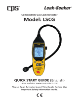
Front panel
Rear panel
Display
for 5 measuring channels
only:
other:
The following only shows the device version with 5 measuring channels.
1 Gas entry
2 Alarm LED
3 Buzzer
4 key
5 key
6 Display
7 Tool for replacing
the sensor
1 IR interface
2 Fastening clip
3 Type plate
4 Charging contacts
5 Power pack
6 Serial no.
1 Measured gas
display
with unit
2 Measured value
display
3 Special symbols
4 Measured gas
display
5 Measured gas
display with unit
6 Special symbols
00223999_02.eps
0
1
2
6
5
4
3
2
X-am 5000
7
OK
00323999_02.eps
2
1
4
6
3
5
00423999_02_en.eps
456
CH4
O
2
CO
%LEL
Vol%
ppm
123
CH4
%LEL
O
2
Vol%
CO
ppm
H
2
S
ppm
NH
3
ppm

10
What is What
Special symbols
Fault message, refer to page 15
Warning message, refer to page 15
The peak value display for all measuring gases,
refer to page 15
The exposure evaluation display (TWA) for measuring gases, e.g., H
2
S and
CO,
refer to page 15
The exposure evaluation display (STEL) for measuring gases, e.g,. H
2
S and
CO,
refer to page 15
The device is set to function test with gas (bump test),
refer to page 32
The device is set to the fresh air calibration function,
refer to page 38
The device is set to the 1-button calibration function,
refer to page 40
The device is set to the single gas calibration function,
refer to page 42
The function for password entry is active,
refer to page 17
Battery / rechargeable battery 100 % full
Battery / rechargeable battery 2/3 full
Battery / rechargeable battery 1/3 full
Battery / rechargeable battery empty

11
Configuration
Configuration
Standard gas configuration
DrägerSensor Measuring
range
1)
1) Different settings can be selected to meet customer requirements on delivery. The current setting can be che-
cked and changed with the Dräger CC Vision software. A version of Dräger CC-Vision suitable for the Dräger
X-am 5000/2000 can be downloaded on the product page of the X-am 5000: www.draeger.com.
Alarm A1
1)
Alarm A2
1)
setpoint
can be
acknowledged
self-latching
setpoint
can be
acknowledged
self-latching
CatEx 125 PR [%LEL]
0 to 100 20 Yes No 40 No Yes
XXS O
2
[vol. %] 0 to 25 19
2)
2) In the case of O
2
A1 is the lower alarm setpoint: an alarm is issued if the value is too low.
No Yes 23 No Yes
XXS O
2
100 [vol. %] 0 to 100 18
2)
No Yes 24 No Yes
XXS CO [ppm] 0 to 2,000 30 Yes No 60 No Yes
XXS CO HC [ppm] 0 to 10,000 600 Yes No 1,200 No Yes
XXS CO H
2
-CP [ppm] 0 to 2.000 30 Yes No 60 No Yes
XXS H
2
[ppm] 0 to 2.000 200 Ye s No 400 No Yes
XXS H
2
S [ppm] 0 to 200 10 Yes No 20 No Yes
XXS H
2
S LC [ppm] 0 to 100 5 Yes No 10 No Yes
XXS H
2
S HC [ppm] 0 to 1,000 100 Yes No 200 No Yes
XXS H
2
S/CO [ppm] 0 to 200 H
2
S
0 to 2,000 CO
10 H
2
S
30 CO Yes No
20 H
2
S
60 CO No Yes
XXS NO [ppm] 0 to 200 25 Yes No 50 No Yes
XXS NO
2
[ppm] 0 to 50 5 Yes No 10 No Yes
XXS SO
2
[ppm] 0 to 100 1 Yes No 2 No Yes
XXS PH
3
[ppm] 0 to 20 0.1 Yes No 0.2 No Yes
XXS PH
3
HC [ppm] 0 to 2,000 5 Yes No 10 No Yes
XXS HCN [ppm] 0 to 50 10 Yes No 20 No Yes
XXS NH
3
[ppm] 0 to 300 50 Yes No 100 No Yes
XXS CO
2
[vol. %] 0 to 5 0.5 Yes No 1 No Yes
XXS Cl
2
[ppm] 0 to 20 0.5 Yes No 1 No Yes
XXS H
2
HC [vol. %] 0 to 4 0.8 Yes No 1.6 No Yes
XXS OV [ppm] 0 to 200 10 Yes No 20 No Yes
XXS OV A [ppm] 0 to 200 10 Yes No 20 No Yes
XXS Odorant [ppm] 0 to 40 10 Yes No 20 No Yes
XXS Amine [ppm] 0 to 100 10 Yes No 20 No Yes
XXS COCI
2
[ppm] 0 to 10 0,1 Yes No 0,2 No Yes
XXS O
3
[ppm] 0 to 10 0,1 Yes No 0,2 Yes No
XXS NO
2
LC [ppm] 0 to 50 0,5 Yes No 1,0 Yes No

12
Activating the Device
Standard device configuration
Changing the standard configuration: See “Configuring the Device” on page 22.
Activating the Device
Before using the device for the first time, insert the supplied batteries or a charged
NiMH power pack T4 (order no. 83 18 704), refer to Replacing the Batteries, page 45.
Charge the rechargeable batteries if necessary, page 46.
The Dräger X-am 5000 is ready for operation.
Function test with gas (bump test)
in Quick Menu
1)
1) Different settings can be selected to meet customer requirements on delivery. The current setting can
be checked and changed with the Dräger CC Vision software. A version of Dräger CC-Vision suitable
for the Dräger X-am 5000/2000 can be downloaded on the product page of the X-am 5000: www.drae-
ger.com.
Quick bump test
Fresh air calibration in Quick Menu
1)
on
Life sign - optical only
1)
on
Switch off
1)
allowed
LEL factor
1)
(ch
4
) 4.4 vol. %
(4.4 vol. % corresponds to 100 %LEL)
Averaging time
1)
15 minutes for STEL
8 hours for TWA
WARNING
After a basic initialization has been carried out with the PC software Dräger CC
Vision, individual alarm settings may have been changed.

13
Operation
Operation
Switching on the device
• Press and hold the key for approx. 3 seconds until the countdown »3.2.1«
shown in the display has elapsed.
− All the display segments, including the visual, audible and vibration alarms, are ac-
tivated for a short time.
− The software version is displayed.
− The device performs a self test.
− The next sensor which is next due for calibration is displayed with the days remai-
ning until the next calibration, e.g., » Ex %LEL CAL 20 «.
− The time until the bump test interval elapses is displayed in days, e.g., » bt 123 «.
− All alarm setpoints A1 and A2 as well as » « (TWA)
1)
and » « (STEL)
*)
for
H
2
S and CO are displayed in succession.
− During the warm-up period of the sensors, the respective display of the measured
value flashes and the special symbol » « (for warning) is displayed. No alarms
are issued during the running-in period of the sensors.
• Press the key to cancel the display of the activation sequence.
Switching off the device
• Press and hold the key and key at the same time until the countdown
»3.2.1« shown in the display has elapsed.
− Before the device is switched off, the visual, audible and vibration alarms are activa-
ted for a short time.
Before entering the workplace
• Switch on the device. The current measured values are shown in the display.
• Observe any warning » « or fault messages » «.
− If one of these special symbols is displayed, appropriate measures, refer to page 24
to page 27, must be taken.
• Check that the gas inlet opening on the device is not covered.
1) Only when activated in the device configuration. Delivery status: not activated.
CAUTION
Check the display and, if necessary, calibrate the instrument and check all alarm
elements before carrying out safety relevant measurements. A bump test must be
performed according to the national regulations.
The device can be operated normally. If the warning message does not go
out automatically during operation, the device must be maintained after
the end of use.
The device is not ready to measure and requires maintenance.
OK
OK
OK

14
Operation
During operation
During operation, the measured values for every measured gas are displayed.
If a measuring range is exceeded or a negative drift occurs, the following displays are
shown instead of the measured value display:
− Excess concentrations of flammable materials can lead to a lack of oxygen.
− For O
2
concentrations below 8 vol. %, a fault is indicated for the Ex channel as
» « instead of the measurement, if the measurement is below the pre-alarm
threshold (not with setting CH4 with measuring range >100 %LEL).
In the event of an alarm, the corresponding displays, including the visual, audible and
vibration alarms, are activated – see “Identifying Alarms” on page 19.
If the measuring range is exceeded significantly on the CatEx channel (very high
concentration of flammable materials), a blocking alarm is triggered. This CatEx
blocking alarm can be acknowledged manually by switching the device off and back on
again in fresh air.
In configuration setting CH
4
with measuring range 100 vol. %, no blocking alarm is
triggered as the heat conductance measurement principle is used.
After the measuring range of the TOX measuring channels has been exceeded tem-
porarily (up to one hour), checking the measuring channels is not necessary.
WARNING
The presence of catalyst poisons in the measured gas (e.g., volatile silicone, sulfur,
heavy metal compounds or halogenated hydrocarbons) can damage the
DrägerSensor CatEx 125 PR. If the sensor cannot be calibrated to the target
concentration anymore, the sensor must be replaced.
The display of the CatEx sensor may be incorrect for measurements in a low-oxygen
atmosphere (<8 vol. % O
2
); this means that reliable measurement with a CatEx
sensor is no longer possible.
In an oxygen enriched atmosphere (>21 vol. % O
2
), the electrical operational safety
cannot be guaranteed; switch off device or remove from the working area.
»«(concentration too high) or
»«(measuring range not reached) or
»«
(blocking alarm).
CAUTION
The measuring range 0 to 100 vol. % CH4 is not suitable for monitoring explosive
mixtures in the measuring range from 0 to 100%LEL.
WARNING
When using a CatEx sensor in the Dräger X-am 5000, a calibration of zero point and
sensitivity must be carried out after an impact load that results in a fresh air display
not equal to zero.

15
Operation
Calling the Info Mode
• In measuring mode, press the key for approx. 3 seconds.
If any warning or fault messages exist, the corresponding information or error codes
are displayed (page 24 to page 30).
Press the key successively for the next display.
The peak values and the exposition values TWA
1)
and STEL
1)
are displayed.
− If no key is pressed for 10 seconds, the device returns automatically to measuring
mode.
Calling the Info-Off Mode
When the device is in a deactivated state, press the key.
The name of the gas, measuring unit and measuring range limit value are displayed for
all channels.
Pressing the key again exits the Info Off mode (or via timeout).
Warning messages are displayed. Numerical codes of warning messages:
see page 24.
key
Fault messages are displayed. Numerical codes of fault messages: see
page 27.
key
The peak values = the maximum measured values in the case of, e.g., CO,
H
2
S, ... or the minimum measured values in the case of O
2
within the storage
interval are displayed
key
The average values of the exposures based on a shift of, e.g., 8 hours (TWA)
of all the active sensors for the exposure evaluation are displayed
key
The short-term values (STEL) = average values of the concentrations over
the average value duration of all the active sensors for the exposure evalua-
tion are displayed
key
The device is in measuring mode again
1) Only when activated in the device configuration. Delivery status: not activated.
OK
OK
OK
OK
OK
OK
OK
OK

16
Operation
Calling the Quick Menu
− Only the fresh air calibration is activated in the quick menu on delivery. The PC soft-
ware Dräger CC Vision can be used to activate the bump test for the quick menu
and/or the function for displaying and deleting peak values.
• In measuring mode, press the key three times.
If no functions have been activated in the quick menu, the device remains in measu-
ring mode.
− You can select the activated functions of the quick menu by pressing the key.
• Press the key to call the selected function.
Possible functions of the quick menu
• Press the key to cancel the active function and to switch to measuring mode.
− If no key is pressed for 60 seconds, the device returns automatically to measuring
mode.
Function test with gas (bump test), refer to page 32
Fresh air calibration, refer to page 38
Displaying and deleting peak values, see below
OK

17
Operation
Calling the Calibration Menu
− The calibration menu can only be accessed by entering a password.
Password on delivery: »001«
− The default password on delivery can be changed using the PC software
Dräger CC Vision.
• In measuring mode, press the key for at least 4 seconds.
− The function for entering the password is selected.
− The » « special symbol (for the "enter password" function) is displayed.
Quick menu "Displaying and
deleting peak values"
After the function has been selected, the
current peak values are displayed; the
peak values special symbol appears in
the display at the same time.
• The peak values can be deleted by
pressing the key for 5 sec.
The adjacent display appears.
• Press the key to end the function.
04823999_01_en.eps
ch4
%LEL
O
2
Vol%
CO
ppm
H
2
S
ppm
NH
3
ppm
04923999_01_en.eps
ch4
%LEL
O
2
Vol%
CO
ppm
H
2
S
ppm
NH
3
ppm
OK
OK

18
Operation
Calibration menu functions
• Press the key to cancel the active function.
− If no key is pressed for 10 minutes, the device automatically returns to measuring
mode.
− The display shows »000«, with the
first digit flashing.
• Use the key to set the flashing digit.
• Press the key, the second digit
starts flashing.
• Use the key to set the flashing digit.
• Press the key, the third digit starts
flashing.
• Use the key to set the flashing digit.
• Press the key to confirm the pass-
word once it has been set completely.
− The calibration menu functions can
now be selected by pressing the
key.
• Press the key to call the selected
function.
Fresh air calibration, refer to page 38
1-button calibration, refer to page 40
Single gas calibration, refer to page 42
02323999_01.eps
OK
OK
OK
OK

19
Identifying Alarms
Identifying Alarms
An alarm is displayed visually, audibly and through vibration in a specific pattern.
Concentration pre-alarm A1
− The pre-alarm A1 is not self-latching and stops when the concentration has dropped
below the alarm setpoint A1.
− In the case of A1 a single tone is audible and the alarm LED flashes.
Acknowledging the pre-alarm:
• Press the key. Only the audible alarm and the vibration alarm are switched off.
Concentration main alarm A2
After leaving the area, if the concentration is less than the alarm setpoint A2:
• Press the key. The alarm messages are switched off.
If the measuring range is exceeded significantly on the CatEx channel (very high
concentration of flammable materials), a blocking alarm is triggered. This CatEx
blocking alarm can be acknowledged manually by switching the device off and back on
again in fresh air.
In configuration setting CH
4
with measuring range 100 vol. %, no blocking alarm is
triggered as the heat conductance measurement principle is used.
The alarm is indicated by an intermittent alarm message:
Display »A1« and measured value alternating: not for O
2
!
The alarm is indicated by an intermittent alarm message:
Display »A2« and measured value alternating:
In the case of A2 a double tone is audible and the alarm LED flashes
twice.
For O
2
:»A1« and measured value alternating = oxygen deficiency
»A2« and measured value alternating = oxygen surplus
DANGER
Leave the area immediately. Danger to life! A main alarm is self-latching and cannot
be acknowledged or cancelled.
CAUTION
The measuring range 0 to 100 vol. % CH
4
is not suitable for monitoring explosive
mixtures in the measuring range from 0 to 100 %LEL.
OK
OK

20
Identifying Alarms
STEL / TWA exposure alarm
− STEL and TWA alarms cannot be acknowledged or canceled.
• Switch off the device. The values for the exposure evaluation are deleted after the
device is switched on again.
Battery pre-alarm
Acknowledging the pre-alarm:
• Press the key. Only the audible alarm and the vibration alarm are switched off.
− The battery still lasts approx. 20 minutes after the first battery pre-alarm.
Battery main alarm
The battery main alarm cannot be acknowledged or canceled:
− The device is automatically switched off again after 10 seconds.
− Before the device is switched off, the visual, audible and vibration alarms are activa-
ted for a short time.
Device alarm
− The device or one or several sensor channels are not ready for operation.
− For remedies, refer to page 24 to page 30.
• If necessary, commission the Dräger Service Center to eliminate the error.
The alarm is indicated by an intermittent alarm message:
Display »A2« and »« (TWA) or » « (STEL) and measured
value alternating:
CAUTION
Leave the area immediately. After this alarm, the deployment of per-
sonnel is subject to the relevant national regulations.
The alarm is indicated by an intermittent alarm message:
Flashing special symbol »« on the right side of the display:
The alarm is indicated by an intermittent alarm message:
Flashing special symbol »« on the right side of the display:
The alarm is indicated by an intermittent alarm message:
Special symbol » « on the right side of the display:
OK
/