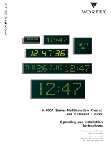
DC.180.4

Mobatime DC.180.4, DC Series, DC.100.4, DC.100.6 User manual

  • Hello! I am an AI chatbot trained to assist you with the Mobatime DC.180.4 User manual. I’ve already reviewed the document and can help you find the information you need or explain it in simple terms. Just ask your questions, and providing more details will help me assist you more effectively!
© MOBATIME BE-800693.16
INSTRUCTION MANUAL
State-of-the-art technology digital clock
DC series
© MOBATIME 2 / 52 800693.16
Certification of the Producer
STANDARDS
The digital clock DC has been developed and produced in accordance with the EU Directives 2014/35/EU
and 2014/30/EU, applied standards:
EN 60950-1:2006/Cor.:2011-10
EN 55022:2010/AC:2011-10, class B
EN 55024:2010/A1:2015
EN 50121-4:2006/Cor.:2008-05
References to the Instruction Manual
1. The information in this Instruction Manual can be changed at any time without notice.
The current version is available for download on www.mobatime.com.
2. This Instruction Manual has been composed with the utmost care, in order to explain all details in
respect of the operation of the product. Should you, nevertheless, have questions or discover errors in
this manual, please contact us.
3. We do not answer for direct or indirect damages, which could occur, when using this Manual.
4. Please read the instructions carefully and only start setting-up the product, after you have correctly
understood all the information for the installation and operation.
5. The installation must only be carried out by skilled staff.
6. It is prohibited to reproduce, to store in a computer system or to transfer this publication in a way or
another, even part of it. The copyright remains with all the rights with RK MOBATIME GmbH,
D-78026 VS-Schwenningen and MOSER-BAER AG CH 3454 Sumiswald / SWITZERLAND.
© MOBATIME 3 / 52 800693.16
Table of contents
1 Description ..................................................................................................................................................... 5
2 Assembly ........................................................................................................................................................ 7
2.1 Single-sided clock .................................................................................................................................... 7
2.2 Double-sided clock ................................................................................................................................... 8
2.3 Dismantling of the clock rear cover .......................................................................................................... 9
2.4 Assembly diagram .................................................................................................................................. 10
2.5 Connecting terminal block ...................................................................................................................... 10
2.6 Control PCB ........................................................................................................................................... 11
2.7 Function of the plug connectors ............................................................................................................. 12
2.8 Setting elements..................................................................................................................................... 12
2.9 Connection of the cable ends ................................................................................................................. 13
3 Control of the clock using keyboard or pushbuttons .............................................................................. 14
3.1 Setting of time and date ......................................................................................................................... 14
3.2 Menu for the setting of the clock parameters ......................................................................................... 15
3.2.1 Submenu for user-specific setting of time constants for data switchover ...................................... 15
3.2.2 Offset setting for time synchronization ........................................................................................... 15
3.2.3 Submenu for network services configuration ................................................................................. 16
3.2.4 Manual setting of the IP address of the clock ................................................................................. 16
3.2.5 Manual setting of the subnet mask ................................................................................................. 16
3.2.6 Manual setting of default gateway IP address ............................................................................... 17
3.2.7 Submenu for setting the multicast group address .......................................................................... 17
3.2.8 Submenu for the setting of the NTP unicast synchronization ........................................................ 17
3.2.9 Submenu for displaying IPv6 addresses ........................................................................................ 18
4 Control of the clock using IR remote control ............................................................................................ 19
4.1 Setting of time and date ......................................................................................................................... 19
4.2 Menu for the setting of the clock parameters ......................................................................................... 20
4.2.1 Submenu for user-specific setting of time constants for data switchover ...................................... 20
4.2.2 Offset setting for time synchronization ........................................................................................... 21
4.2.3 Submenu for network services configuration ................................................................................. 21
4.2.4 Manual setting of the IP address of the clock ................................................................................. 22
4.2.5 Manual setting of the subnet mask ................................................................................................. 22
4.2.6 Manual setting of default gateway IP address ............................................................................... 22
4.2.7 Submenu for setting the multicast group address .......................................................................... 22
4.2.8 Submenu for the setting of the NTP unicast synchronization ........................................................ 23
4.2.9 Submenu for displaying IPv6 addresses ........................................................................................ 23
5 The clock menu table .................................................................................................................................. 24
5.1 IPv6 adress submenu ............................................................................................................................ 26
6 Control of the stopwatch via keyboard ..................................................................................................... 27
6.1 The stopwatch menu .............................................................................................................................. 27
6.2 Setting of the initial time for counting down ........................................................................................... 27
7 Control of the stopwatch using IR remote control ................................................................................... 28
7.1 The stopwatch menu .............................................................................................................................. 28
7.2 Setting of initial time for counting down.................................................................................................. 29
7.3 Switching contact ................................................................................................................................... 29
8 Stopwatch menu table ................................................................................................................................. 30
9 Local time calculation ................................................................................................................................. 32
© MOBATIME 4 / 52 800693.16
9.1 Basic setting control according to source of synchronization ............................................................. 32
9.2 Calculation using MOBALine time zones ............................................................................................... 32
9.3 Calculation using time zone server MOBATIME .................................................................................... 32
9.4 Calculation using time zone entries preconfigured by MOBA-NMS software ........................................ 33
9.5 Calculation according to internal time zone table .................................................................................. 33
10 Non-network clock operation ..................................................................................................................... 34
10.1 Autonomous clock synchronized by DCF 77 receiver ........................................................................... 34
10.2 Autonomous clock synchronized by GPS receiver ................................................................................ 34
10.3 Slave clock controlled by synchronizing impulses ................................................................................. 34
10.3.1 Synchronization and time setting P5 mode 1 and 3 .................................................................... 35
10.3.2 Synchronization only P5 mode 2 and 4 ....................................................................................... 35
10.4 Slave clock controlled by MOBATIME serial code, MOBALine, or IRIG-B ............................................ 35
10.5 Slave clock controlled by IF482 over RS232 or RS485 ......................................................................... 35
10.6 Slave clock controlled by supervised RS485 ......................................................................................... 36
10.7 Cascaded connection of the DCF/GPS synchronized clock .................................................................. 36
10.8 Synchronization in WTD system ............................................................................................................ 36
10.9 Connecting the slave displays through RS485 ...................................................................................... 36
11 NTP and PoE clock operation ..................................................................................................................... 37
11.1 Unicast mode ......................................................................................................................................... 37
11.1.1 Network parameters assignation by DHCP .................................................................................... 38
11.1.2 Manual setting through setup menu ............................................................................................... 38
11.1.3 Manual setting through telnet ......................................................................................................... 38
11.1.4 Setting network parameters over DHCPv6 .................................................................................... 39
11.1.5 Setting network parameters over autoconfiguration (SLAAC) ....................................................... 39
11.1.6 SNMP ............................................................................................................................................. 40
11.2 Multicast mode ....................................................................................................................................... 40
12 WiFi clock operation .................................................................................................................................... 41
12.1 Setting via default MOBA-WIFI wireless network (Configure using) ...................................................... 41
12.2 Setting via AP mode (Configure using) .................................................................................................. 41
12.2.1 Wifi version ..................................................................................................................................... 41
12.2.2 Wifi 2.4/5 GHz version .................................................................................................................... 42
12.3 Setting the network parameters using telnet .......................................................................................... 42
13 Testing mode, parameter reset................................................................................................................... 44
13.1 Synchronization test ............................................................................................................................... 44
13.2 Parameter reset ...................................................................................................................................... 44
14 Firmware update .......................................................................................................................................... 45
14.1 Firmware update using RS232 ............................................................................................................... 45
14.2 Firmware update over Ethernet on NTP and PoE versions ................................................................... 45
15 Time zone table ............................................................................................................................................ 46
16 Engineering data .......................................................................................................................................... 48
16.1 Standard design of the clock .................................................................................................................. 48
16.2 Voltage range and electric current consumption of the lines ................................................................. 48
17 Accessories and Maintenanc...................................................................................................................... 49
17.1 Single-sided clock .................................................................................................................................. 49
17.2 Double-sided clock ................................................................................................................................. 49
18 Cleaning ........................................................................................................................................................ 49
19 DISPOSAL OF USED BATTERIES .............................................................................................................. 49
20 GUARANTEE AND MAINTENANCE ............................................................................................................ 49
© MOBATIME 5 / 52 800693.16
1 Description
General purpose digital clock, intended for indoor use • The clock meets the requirements of
the majority of conventional applications • 7-segment LED display of high luminance provide
for excellent readability from various angles of view • Eight combinations of the height and the
number of digits • Autonomous operation with internal quartz powered from mains • NTP
multicast or unicast synchronization in Ethernet or WiFi network powered over PoE or mains
powered • Slave clock operation in wireless WTD system based on a transmitter which sends
the time signal • Slave clock operation controlled by self-setting MOBALine code mains
powered • Slave clock operation controlled by built-in RS 232, RS 485 or IRIG-B interface,
mains powered • LED display in red, pure green, blue, amber or green • Single or double
sided clock • Clock frame made of anodized aluminum profiles • Wall mounting for single sided
clock • Ceiling suspension or wall bracket mounting for double as well as single sided clock
Basic properties
digit height of 57, 100 or 180 mm, which corresponds to readability distance of approx. 25,
40 or 65 meters
color of the digits: red, pure green, blue, yellow or green
manual or automatic setting of the LED display light intensity
anti-reflex front cover acrylic glass which prevents light reflex and improves the digit
readability
single-sided or double-sided design, for wall mounting (for single-sided clock design,
only), or to be suspended on ceiling or fixed to a side kick up console
depth of single-sided clock design only 39 mm (66 mm for the 180 mm versions) or 78
mm (130 mm) for the double-sided design)
clock frame made of anodized aluminum profiles, in black or silver color. Any other RAL
tint or imitation of various materials (wood, marble…) on request
clock setting carried out remotely or using two push-buttons, the latter installed at the
upper part of the frame
autonomous, quartz controlled time base with the possibility of synchronization using the
following: DCF 77 radio signal, 24 V minute impulses, the MOBATIME serial code,
MOBALine, RS 232, RS 485, IRIG-B or GPS
IPv4 and IPv6 support
NTP multicast or unicast synchronization in Ethernet or unicast synchronization in WiFi
network powered over PoE or mains powered
configuration / supervision by means of MOBA-NMS software or SNMP protocol
slave clock operation in wireless WTD system (868MHz) based on a transmitter which
broadcasts the time signal
possibility to set up the world time zones with indication of the time shift (DST) for the
particular time zone. Control over the DCF receiver or the master clock
© MOBATIME 6 / 52 800693.16
The clocks
time display in 12 or 24 hour cycle; four-digit (HH:MM) or six-digit (HH:MM:SS) format.
Digits of the same height (HH:MM:SS) on request for DC.100 and DC.180;
possibility of leading zero suppression when displaying the time and date;
temperature indication (providing the temperature sensor is connected) in °C or °F.
alternating indication of time, date and temperature, with adjustable period of each of the
displayed data;
Stopwatch
counting up, starting from zero, up to 99 hours;
countdown from a set up value, with stop at zero, automatic restart or counting to
negative values;
indication of intermediate times, “freezing“ of the display, cumulated interim time;
counting in steps of one minute, one second or 1/100 second;
control using the keyboard or IR remote control;
concurrently, possibility of changeover into the time/date display mode, or the temperature
indication.
Accessories
DCF 77 signal receiver
temperature sensor with protection degree IP 66
keyboard for stopwatch control, connected via 5 m cable
remote IR controller for clock set up and stopwatch control
On request
internal relay relay can switch for specified duration, when the stopwatch in the
countdown mode reach the zero.
protection degree IP 54
© MOBATIME 7 / 52 800693.16
2 Assembly
The connection to the 110/230 V AC power network can only be done by authorized personnel
with appropriate qualification and training.
Danger of electric shock when dismounting the cover with warning triangle.
The connection to the 110/230 V AC power network should be carried out when the mains
power is off.
2.1 Single-sided clock
The frame is fixed using two suspension (at the above) and two sliding springs (at
the bottom). Lift-off the anchoring plate using a screwdriver inserted in between the
sheet and the frame at the sliding spring point on the clock bottom side (chapter
2.3).
Disconnect the interconnecting cables by decoupling the terminals on the control
PCB.
Drill three anchoring holes into the wall, of a diameter adequate to accommodate
wood-type screws of 4 to 5 mm diameter. As a template for marking the position of
the holes the anchoring plate can be used.
Interlace the incoming conductors through the opening in the anchoring plate and
fix the sheet to the wall.
Connect the incoming conductors in accordance with the descriptive sheet on the
terminal board, placed on the anchoring plate (chapter 2.5). Give the conductors
an appropriate shape or cut them off to a length that will not obstruct the
placement of the clock onto the anchoring plate.
Mount the connectors to the cable of the temperature sensor, to the keyboard
cable, Ethernet or to the RS 232 and RS 485 interface cables, if these have been
delivered.
Push the temperature sensor connector, the keyboard connector, Ethernet
connector or the RS 232 and RS 485 jacks into the corresponding terminals on the
control PCB (chapter 2.6 and 2.9). Check the marking of the jack-plugs, in order to
prevent their mix-up.
Connect the interconnecting cables into the corresponding terminals on the clock
control PCB.
Put the clock opposite to the anchoring plate and suspend it onto the upper
springs. Care should be taken when placing the cables between the frame edge
and the anchoring plate, so as not to nip them. Snap the clock in onto the springs
by pushing on the lower part of the frame.
Check whether the anchoring plate on the sides fits exactly into the groove in the
clock frame.
Remove the blind cap from the opening on the clock bottom side.
Insert Allen key into the opening on the bottom side of the clock. Turn the key
softly in anticlockwise direction. The frame catch will snap in.
Replace the blind cap on the opening.
To loosen the frame catch, use the reverse procedure (turn clockwise).
© MOBATIME 8 / 52 800693.16
2.2 Double-sided clock
The double-sided clock consists of two parts, one serving as the control module
(this one encompasses the jacks to connect powering voltage, synchronization
source, the temperature sensor and the keyboard to the clock), and the other
serving as the display module (with the terminal for the connection of the
interconnecting cable). Both clock parts are interconnected via a 10-core flat cable.
The clock suspension part is delivered separately.
Interlace the incoming conductors through the pipe which serves as the clock
suspension. Secure the ceiling suspension (or the side console) to the ceiling (or
the wall), using 4 wood screws of 5 mm diameter.
The frame is fixed using two suspensions (at the above) and two sliding springs (at
the bottom). Lift-off both parts of the clock from the anchoring plate using a
screwdriver inserted in between the sheet and the frame at the point where there
are the sliding springs on the clock bottom side (chapter 2.3).
Disconnect the interconnecting cables by decoupling the terminals on the control
PCB.
Interlace the incoming conductors through the pipe insert on the anchoring plate,
to the side which finds itself to the opposite of the terminal board. Slip-on the plate
onto the suspension in a way that the screws fit into the upper groove on the pipe
insert. Fix the connection by tightening the screw using an Allen key.
Interlace the incoming conductors through the opening located next to the terminal
board, and connect the conductors to the terminal board on the anchoring plate, in
accordance with the descriptive nameplate (chapter 2.5). Give an appropriate
shape to the conductors or cut them off at a length which does not obstruct the
mounting of the clock onto the anchoring plate.
Mount the connectors to the cable of the temperature sensor, to the keyboard
cable, Ethernet cable or the RS 232 and RS 485 interface connectors, if these
have been delivered.
Place the display part of the clock to the anchoring plate, at a position which is
opposite to the terminal board, and suspend this part onto the upper springs.
Interlace the 10-core interconnecting cable through the lower opening which finds
itself at the closest to the terminal board on the anchoring plate.
Care should be taken when placing the cables between the frame edge and the
anchoring plate, so as not to nip them. Snap the clock onto the springs by pushing
on the lower frame part.
Connect the 10-core interconnecting cable and the interconnecting cables into the
corresponding plugs on the clock control PCB.
Push the temperature sensor connector, the keyboard connector, Ethernet
connector or the RS 232 and RS 485 jacks into the corresponding terminals on the
control PCB (chapter 2.6). Check the marking of the jack-plugs, in order to prevent
their mix-up.
Put the control part of the clock opposite to the anchoring plate and suspend it
onto the upper springs. Care should be taken when placing the cables between the
frame edge and the anchoring plate, so as not to nip them. Snap the clock in onto
the springs by pushing on the lower part of the frame.
Check whether the anchoring plate on the sides fits exactly into the grooves
established in both parts of the digital clock (these must be pushed against each
other in a way to mask the anchorage plate (after placing the parts the plate shall
not be seen).
Remove the blind cap from the opening on the both lower sides of clock.
© MOBATIME 9 / 52 800693.16
Insert Allen key into the opening on the lower side of the clock. Turn the key softly
in anticlockwise direction. The frame catch will snap in. Secure both parts of the
clock.
Replace the blind cap on the opening.
Loosen the screws on the suspension using Allen key, and lift the clock into the
suspension in a way that the screws fit into the lower groove on the pipe insert.
Secure the attachment by tightening the screw using the Allen key.
To loosen the frame catch, use the reverse procedure (turn clockwise).
Note: during the disassembly first withdraw the clock, and suspend the suspension
on the upper groove at the pipe insert.
2.3 Dismantling of the clock rear cover
© MOBATIME 10 / 52 800693.16
2.4 Assembly diagram
2.5 Connecting terminal block
Note: For PoE version is Ethernet cable plugged directly into the connector on the control board (this version is without
terminal block)
© MOBATIME 11 / 52 800693.16
2.6 Control PCB
© MOBATIME 12 / 52 800693.16
2.7 Function of the plug connectors
LINES, DC/DCF OUTJP1 time signal inputs: The DCF/GPS receiver,
polarized impulse line, MOBALine, MOBATIME
serial code, IRIG-B,
power supply output: DC OUT 1119 V
or passive DCF current loop output
TEMPJP2 connection of the temperature sensor(s)
CTRLJP3 connection of the keyboard
RS232JP4 (optional) connection of the RS232 serial line
RS485JP5 (optional) connection of the RS485 serial line
100 240VACJP6 powering 100 - 240 VAC voltage
LAN - JP7 (optional) RJ45 10BaseT/100TX (IEEE 802.3)
auto negotiation
PROG JP8 clock firmware programming
DISP2JP20 connection of the second side
RELAY JP21(optional) switching contact (except DC.57.4)
2.8 Setting elements
Line type jumper JP11 for the setting of the slave line type
IRIG / AFNOR
DCF
MOBALine
(Un)polarized impulse line
MOBATIME serial code
PB1, PB2 control pushbuttons
RESET the RESET button
TRE jumper JP10 (optional) RS485 terminating resistor enable
BATT jumper JP12 backup battery connection
ISPE jumper JP9 invoking the firmware programming mode
DCF LED indication of receiving the DCF signal
STATE LED state indication
POWER LED power indication
jumper DC Out / DCF Out JP17 Output signal setting on pins 3, 4
of the JP1 connector
pin3 = DC Out + (11-19V)
DC Out
pin4 = DC Out -
pin3 = (+)
passive DCF Out
pin4 = (-)
© MOBATIME 13 / 52 800693.16
2.9 Connection of the cable ends
Installation LINES / DC OUT wire connection
TEMP wire connection 1 or 2 thermometers
CTRL wire connection
RS-232 wire connection
RS-485 wire connection
RELAY connection
© MOBATIME 14 / 52 800693.16
3 Control of the clock using keyboard or pushbuttons
The clock is adjusted and controlled using two pushbuttons located at the
upper side of the clock frame. If you use a keyboard for setting the stopwatch, use the
pushbuttons PB1 and PB2 for the clock setting.
Abbreviations used for the key strokes
PB1L, PB2L pushing the pushbutton for more than 1 second
PB1S, PB2S pushing the pushbutton for less than 1 second
Function of the pushbuttons in the “Clock“ mode
PB1S time correction to the whole minute (±30 sec)
PB2S changeover of the displayed items
Time -> date -> temperature -> stopwatch -> time
PB1L entry into the time and date setting mode
PB2L entry into the clock menu
3.1 Setting of time and date
The setting of time and calendar date takes place in following steps: year days
months hours minutes. The entry into the time and date setting
mode occurs by pushing the PB1L pushbutton.
The display shows the following:
The item to be adjusted
is now blinking.
Move to another item by pushing the PB1S pushbutton. After having adjusted the
minutes and by pushing PB1S, the entered values are stored (the seconds are set to
zero) and the operation of the clock resumes. The clock returns into normal working
mode.
Note: When the time zone of displayed time and date (menu item P7) is set to the
values U1 U7 or U, the entered time and date is taken as UTC.
Function of the pushbuttons in the “Time and date setting“ mode.
PB1S advancement to another item to be set up
PB2S increase of the item to be set up by 1
PB2L continuous increase of the current item
© MOBATIME 15 / 52 800693.16
3.2 Menu for the setting of the clock parameters
The entry into the parameter setup menu is done by pushing the PB2L button.
The display shows the following:
The item to be adjusted
is now blinking
The options for the parameter setup are shown in the clock menu table (chapter 5).
Function of the pushbuttons in the setup menu mode
PB1S storage of the current item and move to another menu item
PB1L storage of values and return into normal display mode, or entry
into the submenu, where it is permitted by the program
PB2S increase of the current item by 1
PB2L continuous increase of the current item
PB1L+PB2L return into normal display mode, without storage of the data
3.2.1 Submenu for user-specific setting of time constants for data switchover
In menu item P2 (time constants for automatic switching over of values), set the
value U, then enter the submenu by pushing PB1L. The item to be set is blinking.
By pushing the PB2S button, the adjusted value is increased in steps of 1, by
pushing the PB2L button, the value will be continuously increased.
The display shows the following:
Enter the time constant for the display of
time in seconds. Push the PB1S button
and enter the constant for date display
in seconds.
Push the PB1S pushbutton.
The display shows the following:
Enter the time constant for the display
of temperature in seconds. Push the
PB1S pushbutton and enter the constant for
stopwatch display in seconds.
By pushing the PB1L button are the entered values stored and the clock returns
to the menu item P2.
3.2.2 Offset setting for time synchronization
Clocks can run with a defined offset to synchronization source.
In menu item P4 (synchronization source), push PB1L to go to the time
synchronization offset setting submenu.
The setting unit is 1/100 second.
Setting range -9.99 to +9.99.
Push PB1L to save the setting and return to menu item P4.
Push together PB1L and PB2L to return to P4 without storage of the data
© MOBATIME 16 / 52 800693.16
3.2.3 Submenu for network services configuration
Choose the value 2 or 3 in the item P19 (network work mode selection) in the
clock menu, then enter the submenu by pushing the PB1L pushbutton for
configuring the network services (Multicast support in unicast work mode, SNMP
service, Telnet service). The item to be set is blinking.
The display shows the following:
Set value 1 for enabling the multicast
support in the unicast work mode or
value 0 for disabling it by pushing the
PB2S.
Switch to the next parameter SNMP communication support by pushing the
PB1S. The display shows the Sn: 1. Set value 1 for enabling the SNMP support
or value 0 for disabling it by pushing the PB2S.
Switch to the next parameter Telnet support by pushing the PB1S. The display
shows the tn: 1. Set value 1 for enabling the telnet support or value 0 for
disabling it by pushing the PB2S.
By pushing PB1L save the setting and return to item P19.
3.2.4 Manual setting of the IP address of the clock
Choose the item P20 in the main menu and push the PB1L button to enter the
submenu for setting the IP address. The item to be set is blinking.
By pushing PB2S, the adjusted digit value is increased in steps of 1, by pushing
the PB2L button, the value will be continuously increased.
The display shows the following: Enter the four octets of the IP address
step by step. Switch to next digit or octet
respectively by pushing the PB1S.
Octets are marked by letters A, b, C
and d.
By pushing the PB1L button, the entered values are stored and the clock returns
to the menu item P20.
3.2.5 Manual setting of the subnet mask
Choose the item P21 in the main menu and push the PB1L button to enter the
submenu for setting the subnet mask. The item to be set is blinking.
By pushing PB2S, the adjusted value is increased in steps of 1, by pushing the
PB2L button, the value will be continuously increased.
The display shows the following:
Enter the four octets of the subnet mask
step by step. Switch to the next octet by
pushing the PB1S button. Octets are
marked by letters A, b, C and d.
By pushing the PB1L button, the entered values are stored and the clock returns
to the menu item P21.
© MOBATIME 17 / 52 800693.16
3.2.6 Manual setting of default gateway IP address
Choose item P22 in the main menu and push the PB1L button to enter the
submenu for setting the default gateway IP address. The item to be set is
blinking.
By pushing PB2S the adjusted digit value is increased in steps of 1, by pushing
the PB2L button the value will be continuously increased.
The display shows the following:
Enter the four octets of the gateway IP
address step by step. Switch to the next
digit or octet respectively by pushing the
PB1S button. Octets are marked by
letters A, b, C and d.
By pushing PB1L button, the entered values are stored and the clock returns to
the menu item P22.
3.2.7 Submenu for setting the multicast group address
Choose the menu item P23 and then enter the submenu by pushing the PB1L
pushbutton for setting the multicast group address. The item to be set is blinking.
By pushing the PB2S button, the adjusted digit value is increased in steps of 1;
by pushing the PB2L button, a continuous increase of the value takes place.
The display shows the following:
Enter the four octets of the IP address step by
step. Switch to the next digit or octet respectively
by pushing the PB1S button. Octets are marked
by the letters A, b, C and d.
By pushing the PB1L button, the entered values are stored and the clock returns
to the menu item P23.
3.2.8 Submenu for the setting of the NTP unicast synchronization
Choose the menu item P24 then enter the submenu by pushing the PB1L
pushbutton for setting the parameters of the NTP unicast synchronization. The
item to be set is blinking.
By pushing the PB2S button, the adjusted digit value is increased in steps of 1;
by pushing the PB2L button, the value will be continuously increased.
© MOBATIME 18 / 52 800693.16
The display shows the following:
Set the four octets of the NTP server’s IP address
step by step. Switch to the next digit or octet
respectively by pushing the PB1S button. Octets
are marked by letters A, b, C and d.
After the last octet setting, set the constant x which determines the interval of
synchronization in seconds.
By pushing the PB1L button, the entered values are stored and the clock returns
to the menu item P24.
Note: Through the setup menu is possible to set only one NTP server IP address.
If more than one NTP server addresses were previously configured (using telnet
or MOBA-NMS tool), after opening the P24 submenu the IP address of currently
active NTP server is displayed. When the IP address was modified and the
configuration is saved using the setup menu, the IP address is stored to the
definition of the first NTP server, the other NTP server addresses are cleared
including those defined by the NTP server domain names.
3.2.9 Submenu for displaying IPv6 addresses
Choose the menu item P25 and push PB1L to enter the IPv6 addresses
submenu. In the submenu choose required IP address for displaying and push
PB1L to display the first part of the IPv6 address.
The IPv6 address consists of a total of 8 parts. You can switch to IPv6 address
particular part by pushing PB1S. The parts are distinguished by the decimal dots
on the last three digits. Decimal dots show the order of each IPv6 address parts
(0-7) in the binary system.
Push together PB1L and PB2L to return to P25.
Example of IPv6 address display 2001: 0db8: 0000: 0012: f68e: 38ff: fee8: 4a13
2001 first part of IPv6 address (000b)
0db8. second part of IPv6 address (001b)
000.0 – third part IPv6 address (010b)
001.2. fourth part of the IPv6 address (011b)
f6.8e fifth part of the IPv6 address (100b)
38.ff. – sixth part of the IPv6 address (101b)
fe.e.8 seventh IPv6 address (110b)
4a.1.3 eighth part of iPv6 address (111b)
© MOBATIME 19 / 52 800693.16
4 Control of the clock using IR remote control
A 2-digit address is assigned to the clock. With the IR remote control the clock can be locked.
The setting of time, date and the clock parameters can only take place at clocks in an
unlocked state.
Function of the pushbuttons in normal display mode
pushing F1 + entry of 2-digit address, unlock the clock with the
using numerical pushbuttons corresponding address
holding down F1 button unlock all clocks within the reach of the IR
beam of the remote control unit
holding down F2 button lock all clocks within the reach of the IR
beam of the remote control unit
holding down F3 button display the address of all locked clocks within
the reach of the IR beam of the remote control
Function of the pushbuttons in the “Clock“ operation mode
SET entry into the time and date setting mode
The + button button brightness increase (not applicable when
P0 is set to A)
The - button button brightness decrease (not applicable when
P0 is set to A)
CLOCK visualization of time
DATE visualization of date
TEMP visualization of temperature
TIMER visualization of stopwatch
MENU entry into the menu of setting of clock
parameters
CLR time correction to the whole minute (±30 sec)
4.1 Setting of time and date
The time and date values are adjusted in the following sequence: year day month
hours minutes. By pushing the SET button, enter the time and date setting mode.
The display shows the following:
The item to be set is blinking.
After having set up the minutes the value is blinking. By pushing the OK button the
value is stored (with seconds reset to zero) and the clock operation resumes. The clock
returns into normal working mode.
Note: When the time zone of displayed time and date (menu item P7) is set to the
values U1 U7 or U, the entered time and date is taken as UTC.
© MOBATIME 20 / 52 800693.16
Function of the pushbuttons in the “Time and date setting“ mode
The + pushbutton increase of the value adjusted, in steps of 1
The pushbutton decrease of the value adjusted, in steps of 1
Holding down the + button continuous increase of the value set up
Holding down the button continuous decrease of the value set up
ESC return into normal display mode, without storage of the
data
>> move to next parameter
<< move to previous parameter
CLR entry of zero or minimum value
OK storage of values set up and return into normal working
mode, followed with seconds reset
Pushbuttons 0–9 entry of the corresponding numerical value
4.2 Menu for the setting of the clock parameters
The entry into the menu for the setting of the clock parameters is done by pushing the
MENU button.
The display shows the following:
The item to be set is blinking.
The options for the parameters to be set up are shown in the menu table on page
(chapter 5).
Function of the pushbuttons in the “MENU“ mode
>> move to next menu item
<< move to previous menu item
The + button increase of the value adjusted,
in steps of 1
The - button decrease of the current value,
in steps of 1
Holding down the + button continuous increase of the value set up
Holding down the button continuous decrease of the value set up
ESC return into the normal working mode,
without storing the modified items
OK storing of the modified items and return
into the normal working mode
SET enter the sub-menu, where it is possible
Pushbuttons 0–9 entry of the corresponding numerical value
Note: During entering the numbers in the octets of the IP addresses the editing to the
next digit moves automatically.
4.2.1 Submenu for user-specific setting of time constants for data switchover
In menu item P2 (time constants for automatic switching over of values) set value
U, then enter the submenu by pushing the SET button. The item to be set is
blinking.The display shows the following:
/