Supermicro 512F-410B Datasheet
- Category
- Computer cases
- Type
- Datasheet

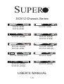
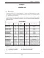
SUPER
®
SC512F-600LB
SC512-260B
SC512-200B
SC512F-520(B)
SC512F-410(B)
SC512L-260(B)
SC512L-200B
SC512C-260(B)
SC512C-200(B)
SC512 Chassis Series
USER’S MANUAL
1.0c
SC512F-600B
SC512F-520L(B)
SC512F-350B
SC512F-280(B)
SC512F-260(B)
SC512L-260(B)-LCD

SC512 Chassis Manual
ii
Manual Revision 1.0c
Release Date: November 2, 2010
The information in this User’s Manual has been carefully reviewed and is believed to be accurate.
The vendor assumes no responsibility for any inaccuracies that may be contained in this document,
makes no commitment to update or to keep current the information in this manual, or to notify any
person or organization of the updates. Please Note: For the most up-to-date version of this
manual, please see our web site at www.supermicro.com.
Super Micro Computer, Inc. ("Supermicro") reserves the right to make changes to the product
described in this manual at any time and without notice. This product, including software and
documentation, is the property of Supermicro and/or its licensors, and is supplied only under a
license. Any use or reproduction of this product is not allowed, except as expressly permitted by
the terms of said license.
IN NO EVENT WILL SUPERMICRO BE LIABLE FOR DIRECT, INDIRECT, SPECIAL, INCIDENTAL,
SPECULATIVE OR CONSEQUENTIAL DAMAGES ARISING FROM THE USE OR INABILITY TO
USE THIS PRODUCT OR DOCUMENTATION, EVEN IF ADVISED OF THE POSSIBILITY OF
SUCH DAMAGES. IN PARTICULAR, SUPERMICRO SHALL NOT HAVE LIABILITY FOR ANY
HARDWARE, SOFTWARE, OR DATA STORED OR USED WITH THE PRODUCT, INCLUDING THE
COSTS OF REPAIRING, REPLACING, INTEGRATING, INSTALLING OR RECOVERING SUCH
HARDWARE, SOFTWARE, OR DATA.
Any disputes arising between manufacturer and customer shall be governed by the laws of Santa
Clara County in the State of California, USA. The State of California, County of Santa Clara shall
be the exclusive venue for the resolution of any such disputes. Super Micro's total liability for all
claims will not exceed the price paid for the hardware product.
California Best Management Practices Regulations for Perchlorate Materials: This Perchlorate
warning applies only to products containing CR (Manganese Dioxide) Lithium coin cells. “Perchlorate
Material-special handling may apply. See www.dtsc.ca.gov/hazardouswaste/perchlorate”
WARNING: Handling of lead solder materials used in this
product may expose you to lead, a chemical known to
the State of California to cause birth defects and other
reproductive harm.
Unless you request and receive written permission from Super Micro Computer, Inc., you may not
copy any part of this document.
Information in this document is subject to change without notice. Other products and companies
referred to herein are trademarks or registered trademarks of their respective companies or mark
holders.
Copyright © 2010 by Super Micro Computer, Inc.
All rights reserved.
Printed in the United States of America

iii
Preface
Preface
About This Manual
This manual is written for professional system integrators and PC technicians. It
provides information for the installation and use of the SC512 1U chassis. Installa-
tion and maintenance should be performed by experienced technicians only.
Supermicro’s SC512 1U chassis features a unique and highly-optimized design
for dual-core Xeon platforms. The chassis is equipped with a 200, 260, 280. 350,
410, 520 or 600 Watt high-efciency power supply for superb power savings. High-
performance fans provide ample optimized cooling for FB-DIMM memory modules
in a 1U form factor.
This document lists compatible parts available when this document was published.
Always refer to the our Web site for updates on supported parts and congura-
tions.

SC512 Chassis Manual
iv
Manual Organization
Chapter 1: Introduction
The rst chapter provides a checklist of the main components included with this
chassis and describes the main features. This chapter also includes contact infor-
mation.
Chapter 2: System Safety
This chapter lists warnings, precautions, and system safety. You should thoroughly
familiarize yourself with this chapter for a general overview of safety precautions
that should be followed before installing and servicing this chassis.
Chapter 3: Chassis Components
Refer to this chapter for details on this chassis model including the fans, bays,
airow shields, and other components.
Chapter 4: System Interface
Refer to this chapter for details on the system interface, which includes the functions
and information provided by the control panel on the chassis as well as other LEDs
located throughout the system.
Chapter 5: Chassis Setup and Maintenance
Follow the procedures given in this chapter when installing, removing, or
reconguring your chassis.
Chapter 6: Rack Installation
Refer to this chapter for detailed information on chassis rack installation. You should
follow the procedures given in this chapter when installing, removing or reconguring
your chassis into a rack environment.
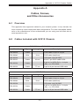
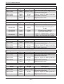
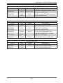
Appendix A Cables, Screws, and Other Accessories
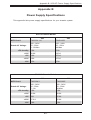
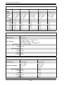
Appendix B Power Supply Specications

v
Preface
Table of Contents
About This Manual .............................................................................................iii
Manual Organization ..........................................................................................iv
Chapter 1 Introduction
1-1 Overview ......................................................................................................... 1-1
1-2 Chassis Features ............................................................................................ 1-2
CPU ................................................................................................................. 1-2
I/O Expansion slots ......................................................................................... 1-2
Peripheral Drives ............................................................................................. 1-2
Dual Hard Drives ............................................................................................. 1-2
1-3 Contacting Supermicro .................................................................................... 1-3
1-4 Returning Merchandise for Service................................................................. 1-4
Chapter 2 System Safety
2-1 Overview ......................................................................................................... 2-1
2-2 Warnings and Precautions .............................................................................. 2-1
2-3 Preparing for Setup ......................................................................................... 2-1
2-4 Electrical Safety Precautions .......................................................................... 2-1
2-5 General Safety Precautions ............................................................................ 2-3
2-6 System Safety ................................................................................................. 2-3
Chapter 3 Chassis Components
3-1 Overview ......................................................................................................... 3-1
3-2 Components .................................................................................................... 3-1
Chassis ............................................................................................................ 3-1
Fans ................................................................................................................ 3-1
Blower ............................................................................................................. 3-1
Mounting Rails ................................................................................................ 3-1
Power Supply .................................................................................................. 3-2
Air Shroud ....................................................................................................... 3-2
3-3 Where to get Replacement Components ........................................................ 3-2
3-4 Chassis Model Options ................................................................................... 3-2
Identifying Fan and Blower-Cooled Chassis Models ...................................... 3-2
Model SC512 .................................................................................................. 3-4
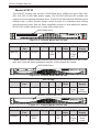
Model SC512C ................................................................................................ 3-5
Model SC512F ................................................................................................ 3-6
Model SC512L ................................................................................................. 3-9

SC512 Chassis Manual
vi
Chapter 4 System Interface
4-1 Overview ......................................................................................................... 4-1
4-2 Control Panel Buttons ..................................................................................... 4-2
4-3 Control Panel LEDs ........................................................................................ 4-2
Chapter 5 Chassis Setup and Maintenance
5-1 Overview ......................................................................................................... 5-1
5-2 Installation Procedures .................................................................................... 5-1
General Maintenance ...................................................................................... 5-1
5-3 Removing the Chassis Cover ......................................................................... 5-2
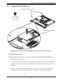
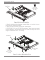
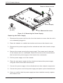
5-4 Installing Hard Drives ...................................................................................... 5-3
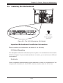
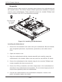
5-5 Installing the Motherboard .............................................................................. 5-5
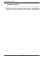
Important Motherboard Installation Information .............................................. 5-5
Standoffs ......................................................................................................... 5-6
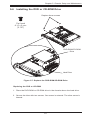
5-6 Installing the DVD or CD-ROM Drive ............................................................. 5-7
PCI Slot Setup ................................................................................................ 5-8
5-7 Installing the Air Shroud .................................................................................. 5-9
Installation Complete ..................................................................................... 5-10
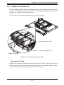
5-8 System Fans/Blower ......................................................................................5-11
System Fan Tray ............................................................................................5-11
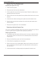
System Fan Tray Replacement..................................................................... 5-12
Blower Setup ................................................................................................. 5-13
5-9 Power Supply ............................................................................................... 5-15
Power Supply Failure .................................................................................... 5-15
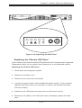
Replacing the Chassis LED Panel ................................................................ 5-17
Chapter 6 Rack Installation
6-1 Overview ......................................................................................................... 6-1
6-2 Unpacking the System .................................................................................... 6-1
6-3 Preparing for Setup ......................................................................................... 6-1
Choosing a Setup Location ............................................................................. 6-1
Rack Precautions ............................................................................................ 6-2
General Server Precautions ............................................................................ 6-2
Rack Mounting Considerations ....................................................................... 6-3
Ambient Operating Temperature ................................................................ 6-3
Reduced Airow ......................................................................................... 6-3
Mechanical Loading ................................................................................... 6-3
Circuit Overloading ..................................................................................... 6-3
Reliable Ground ......................................................................................... 6-3
6-4 Rack Mounting Instructions ............................................................................. 6-4

vii
Preface
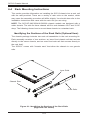
Identifying the Sections of the Rack Rails (Optional Item) ............................. 6-4
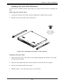
Installing the Inner Rail Extension .................................................................. 6-5
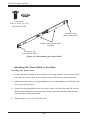
Installing the Outer Rails to the Rack ............................................................. 6-6
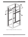
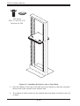
Installing the Chassis into a Rack................................................................... 6-8
Mid-Mount Telco Rack..................................................................................... 6-9
Installing the Chassis into a Rack in Mid-Mount Position .............................. 6-9
Appendix A Cables, Screws, and Other Accessories
Appendix B Power Supply Specications

SC512 Chassis Manual
viii
Notes

Chapter 1
Introduction
1-1 Overview
Supermicro’s SC512 1U chassis features a unique and highly-optimized design.
The chassis is equipped with a high-efciency power supply in a small form factor
for optimized space efciency.
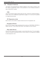
The following chart lists model numbers and features currently available at the
time of printing. For additional information visit the Supermicro Web site at www.
supermicro.com
Chapter 1: Introduction
1-1
SC512 Chassis
Model CPU HDD I/O Slots Power Supply
SC512-200B
UP 1x Fixed 3.5" FH
200W (High-Efciency)
SC512-260B
UP 1x Fixed 3.5" FH 260W
SC512C-200(B)
UP 1x Fixed 3.5" FH 200W
SC512C-260(B)
UP 1x Fixed 3.5" FH 260W
SC512F-260(B)
UP 1x Fixed 3.5" FH 260W
SC512L-200B
UP 2x Fixed 3.5" FH 200W
SC512L-260(B)
UP 2x Fixed 3.5" FH 260W
SC512L-260(B)-LCD
UP 1x Fixed 3.5" FH 260W
SC512F-280(B)
DP/UP 2x Fixed 3.5" FH 280W (High-Efciency)
SC512F-350B
DP/UP 2x Fixed 3.5" FH 350W (Gold Level)
SC512F-410(B)
DP/UP 1x Fixed 3.5" FH 410W DC
SC512F-520(B)
DP/UP 1x Fixed 3.5" FH 520W (High-Efciency)
SC512F-600B
DP/UP 1x Fixed 3.5" FH 600W (Gold Level)
SC512F-520L(B)
DP/UP 1x Fixed 3.5" FH 520W (High-Efciency)
SC512F-600LB
DP/UP 1x Fixed 3.5" FH 600W (Gold Level)
Legend:
DP = Dual Processor Support UP = Single Processor Support
FF = Full-height, Full-length FH = Full-height, Half-length
LP = Low-prole

SC512 Chassis Manual
1-2
1-2 Chassis Features
The SC512 1U high-performance chassis supports a wide range of features. See
the Chassis Components section of this manual for a list of featues included in
each of the SC512 models.
CPU
The SC512 chassis supports a DP and/or UP Xeon, Pentium D, P3/P4 processors.
Please refer to the motherboard specications pages on our web site for updates
on supported processors.
I/O Expansion slots
Each version of the SC512 chassis includes one full I/O expansion slot
Peripheral Drives
Some SC512 chassis support peripheral dives such as a DVD-ROM, CD-ROM or
oppy disk drive. These drives allow data to be installed or saved quickly.
Dual Hard Drives
Some SC512 chassis models support a second hard disk drive. For more details,
check the Chassis Components section of this manual or the Supermicro Website
at www.supermicro.com.

1-3
Chapter 1 Introduction
1-3 Contacting Supermicro
Headquarters
Address: Super Micro Computer, Inc.
980 Rock Ave.
San Jose, CA 95131 U.S.A.
Tel: +1 (408) 503-8000
Fax: +1 (408) 503-8008
Email: [email protected] (General Information)
[email protected] (Technical Support)
Web Site: www.supermicro.com
Europe
Address: Super Micro Computer B.V.
Het Sterrenbeeld 28, 5215 ML
's-Hertogenbosch, The Netherlands
Tel: +31 (0) 73-6400390
Fax: +31 (0) 73-6416525
Email: [email protected] (General Information)
[email protected] (Technical Support)
[email protected] (Customer Support)
Asia-Pacic
Address: Super Micro Computer, Inc.
4F, No. 232-1, Liancheng Rd.
Chung-Ho 235, Taipei County
Taiwan, R.O.C.
Tel: +886-(2) 8226-3990
Fax: +886-(2) 8226-3991
Web Site: www.supermicro.com.tw
Technical Support:
Email: support@supermicro.com.tw
Tel: 886-2-8226-1900

SC512 Chassis Manual
1-4
1-4 Returning Merchandise for Service
A receipt or copy of your invoice marked with the date of purchase is required be-
fore any warranty service will be rendered. You can obtain service by calling your
vendor for a Returned Merchandise Authorization (RMA) number. When returning
to the manufacturer, the RMA number should be prominently displayed on the
outside of the shipping carton, and mailed prepaid or hand-carried. Shipping and
handling charges will be applied for all orders that must be mailed when service
is complete.
For faster service, RMA authorizations may be requested online (http://www.
supermicro.com/support/rma/).
Whenever possible, repack the chassis in the original Supermicro carton, using the
original packaging material. If these are no longer available, be sure to pack the
chassis securely, using packaging material to surround the chassis so that it does
not shift within the carton and become damaged during shipping.
This warranty only covers normal consumer use and does not cover damages in-
curred in shipping or from failure due to the alteration, misuse, abuse or improper
maintenance of products.
During the warranty period, contact your distributor rst for any product problems.

2-1
Chapter 2: System Safety
Chapter 2
System Safety
2-1 Overview
This chapter provides a quick setup checklist to get your chassis up and running.
Following the steps in order given should enable you to have your chassis setup and
operational within a minimal amount of time. This quick setup assumes that you are
an experienced technician, famailiar with common concepts and terminology.
2-2 Warnings and Precautions
You should inspect the box the chassis was shipped in and note if it was damaged
in any way. If the chassis itself shows damage, le a damage claim with carrier
who delivered your system.
Decide on a suitable location for the rack unit that will hold that chassis. It should
be situated in a clean, dust-free area that is well venilated. Avoid areas where heat,
electrical noise and eletromagnetic elds are generated.
You will also need it placed near at least one grounded power outlet. When cong-
ured, the SC512 chassis includes one power supply.
2-3 Preparing for Setup
The SC512 chassis includes a set of rail assemblies, including mounting brackets
and mounting screws you will need to install the systems into the rack. Please read
this manual in its entirety before you begin the installation procedure.
2-4 Electrical Safety Precautions
Basic electrical safety precautions should be followed to protect yourself from harm
and the SC512 from damage:
Be aware of the locations of the power on/off switch on the chassis as well •
as the room’s emergency power-off switch, disconnection switch or electrical
outlet. If an electrical accident occurs, you can then quickly remove power from
the system.
Do not work alone when working with high-voltage components.•

SC512F Chassis Manual
2-2
Power should always be disconnected from the system when removing or install-•
ing main system components, such as the serverboard, memory modules and
the DVD-ROM and peripheral drives (not necessary for hot-swappable drives).
When disconnecting power, you should rst power down the system with the
operating system and then unplug the power cords from all the power supply
modules in the system.
When working around exposed electrical circuits, another person who is fa-•
miliar with the power-off controls should be nearby to switch off the power, if
necessary.
Use only one hand when working with powered-on electrical equipment. This •
is to avoid making a complete circuit, which will cause electrical shock. Use
extreme caution when using metal tools, which can easily damage any electrical
components or circuit boards they come into contact with.
Do not use mats designed to decrease electrostatic discharge as protection from •
electrical shock. Instead, use rubber mats that have been specically designed
as electrical insulators.
The power cord must include a grounding plug and must be plugged into a •
grounded electrical outlet.
Serverboard battery: CAUTION - There is a danger of explosion if the onboard •
battery is installed upside down, which will reverse its polarities This battery
must be replaced only with the same or an equivalent type recommended by
the manufacturer. Dispose of used batteries according to the manufacturer’s
instructions.
DVD-ROM laser: CAUTION - This server may have come equipped with a •
DVD-ROM drive. To prevent direct exposure to the laser beam and hazardous
radiation exposure, do not open the enclosure or use the unit in any uncon-
ventional way.

2-3
Chapter 2: System Safety
2-5 General Safety Precautions
Keep the area around the chassis clean and free of clutter.•
Place the chassis top cover and any system components that have been re-•
moved away from the system or on a table so that they won’t accidentally be
stepped on.
While working on the system, do not wear loose clothing such as neckties and •
unbuttoned shirt sleeves, which can come into contact with electrical circuits or
be pulled into a cooling fan.
Remove any jewelry or metal objects from your body, which are excellent metal •
conductors that can create short circuits and harm you if they come into contact
with printed circuit boards or areas where power is present.
After accessing the inside of the system, close the system back up and secure •
it to the rack unit with the retention screws after ensuring that all connections
have been made.
2-6 System Safety
Electrostatic discharge (ESD) is generated by two objects with different electrical
charges coming into contact with each other. An electrical discharge is created to
neutralize this difference, which can damage electronic components and printed
circuit boards. The following measures are generally sufcient to neutralize this
difference before contact is made to protect your equipment from ESD:
Do not use mats designed to decrease electrostatic discharge as protection from •
electrical shock. Instead, use rubber mats that have been specically designed
as electrical insulators.
Use a grounded wrist strap designed to prevent static discharge.•
Keep all components and printed circuit boards (PCBs) in their antistatic bags •
until ready for use.
Touch a grounded metal object before removing any board from its antistatic •
bag.

SC512F Chassis Manual
2-4
Do not let components or PCBs come into contact with your clothing, which may •
retain a charge even if you are wearing a wrist strap.
Handle a board by its edges only; do not touch its components, peripheral chips, •
memory modules or contacts.
When handling chips or modules, avoid touching their pins.•
Put the serverboard and peripherals back into their antistatic bags when not •
in use.
For grounding purposes, make sure your computer chassis provides excellent •
conductivity between the power supply, the case, the mounting fasteners and
the serverboard.

3-1
Chapter 3: Chassis Components
Chapter 3
Chassis Components
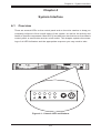
3-1 Overview
This chapter describes the most common components included with your chassis.
Some components listed may not be included or compatible with your particular
chassis model. For more information, see the installation instructions detailed later
in this manual.
3-2 Components
Chassis
Depending on the model, the SC512 chassis may include one slim DVD-ROM/CD-
ROM bay, at least one xed hard drive, a oppy drive, and/or two USB ports. For
the latest shipping lists, visit our Web site at: http://www.supermicro.com.
Fans
The SC512 model chassis accepts two or three system fans powered by the moth-
erboard. These fans are 1U high and are powered by 4-pin connectors.
Blower
The SC512, SC512L and SC512C model chassis use a single blower unit for
system cooling.
Mounting Rails
The SC512 can be placed in a rack for secure storage and use. To set up your
rack, follow the step-by-step instructions included in this manual. SC512 models
with narrow chassis designs include specialized rails for mounting in a standard
rack. See the Rack Installation section of this manual for details.

SC512 Chassis Manual
3-2
Power Supply
Each SC512 chassis model includes a high-efciency power supply rated at 200,
260, 280, 350, 410 or 580 Watts. In the unlikely event your power supply fails,
replacement is simple and can be done without tools.
Air Shroud
Air shrouds are shields, usually plastic, that funnel air directly to where it is needed.
Always use the air shroud included with your chassis.
3-3 Where to get Replacement Components
Though not frequently, you may need replacement parts for your system. To en-
sure the highest level of professional service and technical support, we strongly
recommend purchasing exclusively from our Supermicro Authorized Distributors/
System Integrators/Resellers. A list of Supermicro Authorized Distributors/System
Integrators/Reseller can be found at: http://www.supermicro.com. Click the Where
to Buy link.
3-4 Chassis Model Options
The following section lists the different options which are available for each of the
different chassis models in the SC512 chassis family of products.
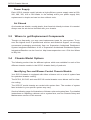
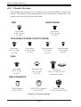
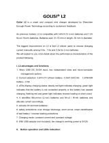
Identifying Fan and Blower-Cooled Chassis Models
Your SC512 chassis is equipped with either a blower unit or a set of system fans
for optimized chassis cooling.
The SC512, SC512C and most SC512L model chassis use a blower unit for chas-
sis cooling.
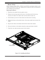
The SC512F model chassis are cooled with system fans. The number of system
fans included in your specic system may vary.
See the following page for illustrations of blower units and system fans. For detailed
instructions on replacing a blower unit or system fans, see the Chassis Setup and
Maintenance section of this manual.

3-3
Chapter 3: Chassis Components
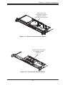
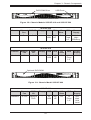
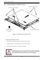
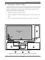
Figure 3-1: Blower-Cooled Chassis Model
Air blower unit
included in chassis
models SC512,
SC512C and SC512L
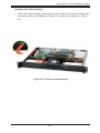
Figure 3-2: Fan-Cooled Chassis Model
System fans included
in chassis model
SC512F

SC512 Chassis Manual
3-4
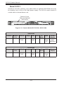
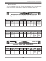
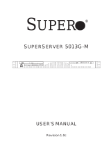
Model SC512
Includes a slot with a dummy cover plate where an optional DVD-ROM drive may
be installed, and a 200 or 260 Watt power supply. The SC512 model chassis is
cooled with an internal blower unit.
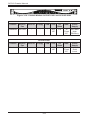
Figure 3-3: Chassis Model SC512-200, SC512-260
Dummy Cover
Plate for Optional
DVD Drive
SC512-200
Chassis Blower/
Fan
DVD/CD Floppy USB CPU I/O
Slots
HDD Power
Supply
Standard Blower Optional
DVD
- 2x
USB
UP FH 1x
Fixed
3.5"
200 Watt
High-
Efciency
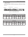
SC512-260
Chassis Blower/
Fan
DVD/CD Floppy USB CPU I/O
Slots
HDD Power
Supply
Standard Blower Optional
DVD
- 2x
USB
UP FH 1x
Fixed
3.5"
260 Watt
Page is loading ...
Page is loading ...
Page is loading ...
Page is loading ...
Page is loading ...
Page is loading ...
Page is loading ...
Page is loading ...
Page is loading ...
Page is loading ...
Page is loading ...
Page is loading ...
Page is loading ...
Page is loading ...
Page is loading ...
Page is loading ...
Page is loading ...
Page is loading ...
Page is loading ...
Page is loading ...
Page is loading ...
Page is loading ...
Page is loading ...
Page is loading ...
Page is loading ...
Page is loading ...
Page is loading ...
Page is loading ...
Page is loading ...
Page is loading ...
Page is loading ...
Page is loading ...
Page is loading ...
Page is loading ...
Page is loading ...
Page is loading ...
Page is loading ...
Page is loading ...
Page is loading ...
Page is loading ...
Page is loading ...
Page is loading ...
Page is loading ...
Page is loading ...
Page is loading ...
Page is loading ...
Page is loading ...
Page is loading ...
Page is loading ...
Page is loading ...
-
 1
1
-
 2
2
-
 3
3
-
 4
4
-
 5
5
-
 6
6
-
 7
7
-
 8
8
-
 9
9
-
 10
10
-
 11
11
-
 12
12
-
 13
13
-
 14
14
-
 15
15
-
 16
16
-
 17
17
-
 18
18
-
 19
19
-
 20
20
-
 21
21
-
 22
22
-
 23
23
-
 24
24
-
 25
25
-
 26
26
-
 27
27
-
 28
28
-
 29
29
-
 30
30
-
 31
31
-
 32
32
-
 33
33
-
 34
34
-
 35
35
-
 36
36
-
 37
37
-
 38
38
-
 39
39
-
 40
40
-
 41
41
-
 42
42
-
 43
43
-
 44
44
-
 45
45
-
 46
46
-
 47
47
-
 48
48
-
 49
49
-
 50
50
-
 51
51
-
 52
52
-
 53
53
-
 54
54
-
 55
55
-
 56
56
-
 57
57
-
 58
58
-
 59
59
-
 60
60
-
 61
61
-
 62
62
-
 63
63
-
 64
64
-
 65
65
-
 66
66
-
 67
67
-
 68
68
-
 69
69
-
 70
70


Supermicro 512F-410B Datasheet
- Category
- Computer cases
- Type
- Datasheet
Ask a question and I''ll find the answer in the document
Finding information in a document is now easier with AI
Related papers
-
SUPER MICRO Computer CSE-512F-350B User manual
-
Supermicro MCP-290-00053-0N Datasheet
-
Supermicro SuperChassis 417E16-R1400LPB User manual
-
-
-
-
-
-
Supermicro SC846TQ-R900B User manual
-
Other documents
-
Spectrum Industries 97507B Assembly Instructions
-
 George Kovacs GKLR096-467 User manual
-
Gigabyte W291-Z00 Installation Instructions Manual
-
Broan B6EW Installation guide
-
 StarTech.com SCREWNUTM Datasheet
-
Sophos ES1100 Setup Manual
-
Advantech M82-PWS-8033M User manual
-
 Enough Power Technology GOLISI L2 User manual
-
Dell W-ClearPass Hardware Appliances Installation guide
-
 Supero SuperServer 5013G-M User manual


