VigilLink VLMX-862HT70 User manual
- Category
- Video switches
- Type
- User manual
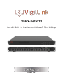
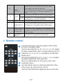
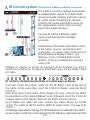
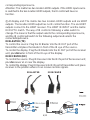
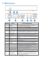
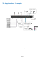
VigilLink VLMX-862HT70 is an 8x6+2 HDMI 2.0 Matrix over HDBaseT with a transmission range of up to 230ft/70m. It supports 4K2K@60Hz (4:4:4) resolution, HDR, and HDCP 2.2. The matrix can be controlled via the front panel button, IR remote control, RS-232, TCP/IP, or Web GUI.
VigilLink VLMX-862HT70 is an 8x6+2 HDMI 2.0 Matrix over HDBaseT with a transmission range of up to 230ft/70m. It supports 4K2K@60Hz (4:4:4) resolution, HDR, and HDCP 2.2. The matrix can be controlled via the front panel button, IR remote control, RS-232, TCP/IP, or Web GUI.


-
 1
1
-
 2
2
-
 3
3
-
 4
4
-
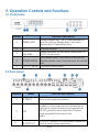 5
5
-
 6
6
-
 7
7
-
 8
8
-
 9
9
-
 10
10
-
 11
11
-
 12
12
-
 13
13
-
 14
14


VigilLink VLMX-862HT70 User manual
- Category
- Video switches
- Type
- User manual
VigilLink VLMX-862HT70 is an 8x6+2 HDMI 2.0 Matrix over HDBaseT with a transmission range of up to 230ft/70m. It supports 4K2K@60Hz (4:4:4) resolution, HDR, and HDCP 2.2. The matrix can be controlled via the front panel button, IR remote control, RS-232, TCP/IP, or Web GUI.
Ask a question and I''ll find the answer in the document
Finding information in a document is now easier with AI
Related papers
-
VigilLink VLMX-431HT70 User manual
-
VigilLink VLPT-42H100 User manual
-
 VigilLink VLSP-18H20 User manual
-
 VigilLink VL-SP18-1 User manual
-
VigilLink VLEX-HT2150-TR User manual
-
 VigilLink VLEX-HT2070R-TR User manual
-
VigilLink VL-EX150MU-1 User manual
-
 VigilLink VLWP-UHS-TR User manual
-
 VigilLink VLEX-CatH2070-TR 18Gbps Cat Extender User manual
-
VigilLink VLEX-HT2150K-TR User manual


Other documents
-
 Scion-Tech SC35.MX44 User manual
-
ALFAtron ALF-MUH88E GEN2 18Gbps 8×8 HDBaseT Matrix User manual
-
-
Smart-AVI HDR-8×8-XT User manual
-
Comprehensive CSW-HDBT44K330 User manual
-
infobit H44H150 User manual
-
CYP PUV-44XPL-AVLC-KIT User manual
-
Triax HMX 884 LP4K User manual
-
 Altimium SCAM82TS User manual
-
PTN MUH44E KIT User manual

