Page is loading ...

12/24VDC
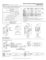
Operating Voltage
Current Draw 300mA/12VDC, 150mA/24VDC
Operating Temperature 32˚F to 120˚F (0˚C to 49˚C)
Humidity 0% to 85% Non-condensing
Latch Throw
1 6/17” (36mm)
3/4"(19mm) (5/8"(16mm) strike
depth, 1/8''(3mm) door gap)
Keeper Width
Static Strength 1500 lbs (680Kg)
(UL Witness test: 2000lbs)
Dynamic Strength 70 ft-lbs
Endurance 250,000 cycles (UL tested)
1,000,000 cycles (Factory tested)
Copyright © All rights reserved. P-MU-GK360-N Published: 2022.05.27
Model Latch Monitor Body Construction
GK360-1224
GK360-ST-1224
GK360M-1224
GK360M-ST-1224
Zinc Alloy
Stainless Steel
Zinc Alloy
Stainless Steel
Fail-Secure:
The GK360/361 series electric strikes are designed to accommodate cylindrical locksets with up to 3/4” (19mm) latch throw.
The strikes can be configured to fail-safe or fail-secure on site.
Electric Strike Installation Instructions
GK360/361 Series
For indoor use only.
Wiring methods shall be in accordance with NFPA70.
The GK360 series is intended to be used with UL Listed
Exit Hardware.
The GK360 series shall not impair the intended operation
of an emergency exit.
The GK360 series shall not impair the operation of panic
hardware mounted on the door.
Fail-Safe:
GK361-1224
GK361-ST-1224
GK361M-1224
GK361M-ST-1224
Zinc Alloy
Stainless Steel
Zinc Alloy
Stainless Steel
Note:
For GK360-ST-1224,GK361-ST-1224,GK360M-ST-1224,GK361M-ST-1224,
remove the “Listed Fire Rated Hardware” label if the strike is used
in the fail safe operation. Using the above-mentioned strikes in Fail
Safe operation negates the fire rating.
Destructive Attack: Level I
Line Security: Level I
Standby Power: Level I
Endurance: Level IV
Performance Level
9/16” (123.8mm)
3 3/8” (85.5mm)
1 1/4”(31.75mm)
11/16” (17mm)
CL
CL
7 15/16” (201.6mm)
1 7/16” (36.5mm)
11/16” (17mm)
CL
CL
3 3/8” (85.5mm)
GK360 Series
GK361 Series
Frame Application
Wood Frame Installation Hollow Metal Frame Installation
Change screw position at fail-safe /fail-secure hole to
the desired setting.
Faceplate
Keeper
Latch Monitor
Strike Body
(17mm)
1 1/4” (31.75mm)
4 7/8” (123.8mm)
1 11/16” (43mm)
(29.5mm)
3 3/8” (85.5mm)
1 3/16”
1 1/16”
1/8”
4 1/8” (105mm)
1 7/16 ” (36.5mm)
(2.5mm)
7 15/16” (201.6mm)
1 7/16”
3 3/8” (85.5mm)
(17mm)
1 1/16”
(2.5mm)
1/8”
(36.5mm)
7 1/16” (180mm)
1 7/16 ” (36.5mm)
1 11/16” (43mm)

Copyright © All rights reserved. P-MU-GK360-N Published: 2022.05.27
Using the Trim Plate
Latch monitor wires
Rated: 0.3A/6VDC
Blue: N.O.
Green: COM.
Yellow: N.C.
Proper gap must be reserved between the strike keeper and latch bolt to prevent failure of solenoid valve.
Connecting Diagram
Optional Brackets
Installation Instructions
Lip extension brackets are available for wider jambs.
12/24 VDC Plug-In Wiring
/