Page is loading ...

Satellite Television
KVHTracVision
®
L3
owner’s manual
• Installation Instructions
• User’s Guide
• Technical Manual
A Guide to TracVision L3

Congratulations!
You have selected one of the most advanced land-mobile satellite
tracking systems available today. KVH
®
Industries’ TracVision
®
L3
is designed for use with European and North American DVB-
compatible satellite services as well as DIRECTV
®
. This manual
provides detailed instructions on the proper installation, use, and
maintenance of your TracVision L3 system.
Throughout this manual, important information is marked for
your attention by these icons:
Direct questions, comments, or suggestions to:
KVH Industries, Inc. KVH Europe A/S
50 Enterprise Center Ved Klaedebo 12
Middletown, RI 02842 USA 2970 Hoersholm Denmark
tel: +1 401 847-3327 tel: +45 45 16 01 80
fax: +1 401 849-0045 fax: +45 45 86 70 77
internet: http://www.kvh.com internet: http://www.kvh.dk
KVH Part # 54-0157 Rev. C
© 2000, KVH Industries, Inc.

TracVision
®
and KVH
®
are registered trademarks of
KVH Industries, Inc.
DIRECTV
®
is an official trademark of DIRECTV, Inc.,
a unit of GM Hughes Electronics.
DISH
™
Network is an official trademark of
EchoStar Communications Corporation.
ExpressVu is a property of Bell ExpressVu, a wholly owned
subsidiary of Bell Satellite Services.

Table of Contents
1 Introduction . . . . . . . . . . . . . . . . . . . . . . . . . . . . . . .1-1
1.1 Digital Satellite Television . . . . . . . . . . . . . . . . . . . . . . . . . . . . . .1-1
1.2 TracVision L3 System Overview . . . . . . . . . . . . . . . . . . . . . . . . .1-2
1.2.1 TracVision L3 Components . . . . . . . . . . . . . . . . . . . . . . . . .1-3
1.2.2 Integrated Receiver Decoder . . . . . . . . . . . . . . . . . . . . . . .1-4
1.3 Materials Provided with TracVision L3 . . . . . . . . . . . . . . . . . . . .1-4
1.3.1 Additional Materials required for TracVision L3 Use . . . . . . .1-5
2 Installation . . . . . . . . . . . . . . . . . . . . . . . . . . . . . . . .2-1
2.1 Choosing the Best Location . . . . . . . . . . . . . . . . . . . . . . . . . . . .2-2
2.2 Mounting the Antenna Unit . . . . . . . . . . . . . . . . . . . . . . . . . . . . .2-2
2.3 Wiring the TracVision L3 System . . . . . . . . . . . . . . . . . . . . . . . .2-6
2.3.1 Wiring the Antenna Data Cable . . . . . . . . . . . . . . . . . . . . . .2-8
2.3.2 Wiring the Antenna Unit Power Cable . . . . . . . . . . . . . . . . .2-9
2.3.3 Connecting to Vehicle Power . . . . . . . . . . . . . . . . . . . . . . .2-10
2.3.4 IRD Ground Wire . . . . . . . . . . . . . . . . . . . . . . . . . . . . . . .2-11
2.3.5 Installing the Switchplate . . . . . . . . . . . . . . . . . . . . . . . . .2-11
2.3.6 Connecting the Antenna RF Signal Cable to the IRD . . . .2-12
2.3.6.1 Installing Two IRDs and TVs (North American
Systems Only) . . . . . . . . . . . . . . . . . . . . . . . . . . . . . . .2-13
2.3.6.2 Connecting Three or More IRDs and TVs
(North American Systems Only) . . . . . . . . . . . . . . . . . .2-13
2.4 Selecting the Active Satellite . . . . . . . . . . . . . . . . . . . . . . . . . .2-15
2.4.1 Installing Your Selected Satellites . . . . . . . . . . . . . . . . . . .2-16
2.4.2 Programming User-defined Satellites . . . . . . . . . . . . . . . .2-17
2.5 Setting the Skew Angle (European Systems Only) . . . . . . . . .2-21
2.6 Checking Out the System . . . . . . . . . . . . . . . . . . . . . . . . . . . . .2-22
2.7 Configuring TracVision L3 for Remote
Satellite Dish Operation . . . . . . . . . . . . . . . . . . . . . . . . . . . . . .2-23
i
54-0157 Rev. C

ii
3 Using Your TracVision L3 . . . . . . . . . . . . . . . . . . . . . . .3-1
3.1 Turning on the System . . . . . . . . . . . . . . . . . . . . . . . . . . . . . . . .3-1
3.2 Changing Channels and Switching to the Second Satellite . . .3-2
3.3 Watching TV on the Move and at Rest . . . . . . . . . . . . . . . . . . . .3-3
4 Troubleshooting . . . . . . . . . . . . . . . . . . . . . . . . . . . . .4-1
4.1 Causes and Remedies for Common Operational Issues . . . . . .4-1
4.1.1 Blown Fuse or Improper Wiring . . . . . . . . . . . . . . . . . . . . . .4-2
4.1.2 Incorrect Satellite Configuration . . . . . . . . . . . . . . . . . . . . .4-2
4.1.3 Satellite Signal Blocked . . . . . . . . . . . . . . . . . . . . . . . . . . .4-2
4.1.4 Dew or Rain Pooling on Dome . . . . . . . . . . . . . . . . . . . . . .4-3
4.1.5 Outside Satellite Coverage Zone . . . . . . . . . . . . . . . . . . . .4-3
4.1.6 Vehicle Turning During Startup . . . . . . . . . . . . . . . . . . . . . .4-3
4.1.7 Incorrect or Loose RF Connectors . . . . . . . . . . . . . . . . . . .4-3
4.1.8 Using a Passive Multiswitch (North American Systems Only)4-4
4.2 IRD Troubleshooting . . . . . . . . . . . . . . . . . . . . . . . . . . . . . . . . . .4-4
4.2.1 IRD Wiring . . . . . . . . . . . . . . . . . . . . . . . . . . . . . . . . . . . . .4-4
4.2.2 IRD Faulty . . . . . . . . . . . . . . . . . . . . . . . . . . . . . . . . . . . . .4-4
4.3 Antenna Gyro and LNB Faults . . . . . . . . . . . . . . . . . . . . . . . . . .4-4
4.4 Computer Diagnostics . . . . . . . . . . . . . . . . . . . . . . . . . . . . . . . .4-4
4.5 Maintenance Port Parser Commands . . . . . . . . . . . . . . . . . . . . .4-5
5 Maintenance . . . . . . . . . . . . . . . . . . . . . . . . . . . . . . .5-1
5.1 Warranty/Service Information . . . . . . . . . . . . . . . . . . . . . . . . . . .5-1
5.2 Preventive Maintenance . . . . . . . . . . . . . . . . . . . . . . . . . . . . . . .5-1
5.3 Replaceable Parts . . . . . . . . . . . . . . . . . . . . . . . . . . . . . . . . . . . .5-2
5.4 Field Replaceable Unit Procedures . . . . . . . . . . . . . . . . . . . . . .5-3
5.4.1 PCB Removal and Replacement . . . . . . . . . . . . . . . . . . . . .5-5
5.4.2 RF Detector/DVB Decoder . . . . . . . . . . . . . . . . . . . . . . . . .5-6
5.4.3 Antenna Gyro Assembly . . . . . . . . . . . . . . . . . . . . . . . . . . .5-6
5.4.4 Antenna LNB Replacement . . . . . . . . . . . . . . . . . . . . . . . .5-7
5.5 Preparation for Shipment . . . . . . . . . . . . . . . . . . . . . . . . . . . . . .5-8

Appendix A System Specifications . . . . . . . . . . . . . . . . . .A-1
Appendix B Functional Block Diagram . . . . . . . . . . . . . . . .B-1
Appendix C Switchplate Template . . . . . . . . . . . . . . . . . .C-1
Appendix D Predefined Satellite Configurations . . . . . . . . .D-1
Appendix E Startup Data Sequence . . . . . . . . . . . . . . . . . .E-1
Appendix F Maintenance Port Parser Commands . . . . . . . . .F-1
F.1 System Commands . . . . . . . . . . . . . . . . . . . . . . . . . . . . . . . . . . .F-1
F.2 Manual Positioning Commands . . . . . . . . . . . . . . . . . . . . . . . . .F-2
F.3 Operational Commands . . . . . . . . . . . . . . . . . . . . . . . . . . . . . . .F-4
F.4 Tracking and Conical Scan Commands . . . . . . . . . . . . . . . . . . .F-4
F.5 RF Board Commands . . . . . . . . . . . . . . . . . . . . . . . . . . . . . . . . .F-5
F.6 Installation Commands . . . . . . . . . . . . . . . . . . . . . . . . . . . . . . . .F-6
F.7 Debug Commands . . . . . . . . . . . . . . . . . . . . . . . . . . . . . . . . . . .F-8
List of Figures
Figure 1-1 TracVision L3 System Configuration . . . . . . . . . . . . . . . . .1-2
Figure 1-2 Primary Components of the TracVision L3 . . . . . . . . . . . .1-3
Figure 2-1 Proper Orientation of the Antenna Unit . . . . . . . . . . . . . . .2-3
Figure 2-2 Elevation Shipping Restraint . . . . . . . . . . . . . . . . . . . . . . .2-3
Figure 2-3 Baseplate Shipping Restraints . . . . . . . . . . . . . . . . . . . . .2-3
Figure 2-4 Mounting the Unit on a Curved Surface . . . . . . . . . . . . . .2-4
Figure 2-5 Baseplate Dimensions . . . . . . . . . . . . . . . . . . . . . . . . . . .2-4
Figure 2-6 Connectors Facing Rear of Vehicle –
Factory-drilled Drain Hole Locations . . . . . . . . . . . . . . . . .2-5
Figure 2-7 Connectors Facing Front of Vehicle –
Recommended Drain Hole Locations . . . . . . . . . . . . . . . .2-5
Figure 2-8 Proper Wire-to-Terminal Connection . . . . . . . . . . . . . . . . .2-6
Figure 2-9 Moving the Antenna Reflector . . . . . . . . . . . . . . . . . . . . . .2-6
Figure 2-10 Cable Port Assignments (Exterior of Baseplate) . . . . . . . .2-7
iii
54-0157 Rev. C

Figure 2-11 Cable Overlap within the TracVision L3 Baseplate . . . . . . .2-7
Figure 2-12 Switchplate Panel Cutout Dimensions . . . . . . . . . . . . . . . .2-8
Figure 2-13 Proper Terminal Strip Wiring Arrangement
– Data Cable . . . . . . . . . . . . . . . . . . . . . . . . . . . . . . . . . .2-8
Figure 2-14 Antenna Data Cable Wiring Arrangement . . . . . . . . . . . . .2-9
Figure 2-15 Proper Terminal Strip Wiring Arrangement
– Power Cable . . . . . . . . . . . . . . . . . . . . . . . . . . . . . . . . .2-9
Figure 2-16 Power Cable Wiring Arrangement . . . . . . . . . . . . . . . . . .2-10
Figure 2-17 Vehicle Power Wiring Arrangement . . . . . . . . . . . . . . . . .2-10
Figure 2-18 Mounting the Switchplate Support Frame
and Front Cover . . . . . . . . . . . . . . . . . . . . . . . . . . . . . . .2-11
Figure 2-19 Connecting the RF Cable to TracVision L3 . . . . . . . . . . .2-12
Figure 2-20a-d Attaching the KVH-provided F-connector
to an RF Cable . . . . . . . . . . . . . . . . . . . . . . . . . . . . . . . .2-12
Figure 2-21 Installing Three or More IRDs Using an Active
Multiswitch (North American Systems Only) . . . . . . . . . .2-14
Figure 2-22 Skew Adjustment (European Systems Only) . . . . . . . . . .2-21
Figure 2-23 Remote Dish Wiring Configuration . . . . . . . . . . . . . . . . .2-23
Figure 3-1 Be Aware of Objects that Might Block
the Satellite Signals . . . . . . . . . . . . . . . . . . . . . . . . . . . . .3-1
Figure 3-2 Turning on the TracVision L3 Using the Switchplate . . . . .3-1
Figure 5-1 Antenna, PCB, and Rotating Plate . . . . . . . . . . . . . . . . . .5-3
Figure 5-2 Close-up of Linear Actuator, Pivot Bracket, and Pin . . . . .5-3
Figure 5-3 Antenna Assembly . . . . . . . . . . . . . . . . . . . . . . . . . . . . . .5-4
Figure 5-4 Close-up of RF Detector and PCB . . . . . . . . . . . . . . . . . .5-4
Figure 5-5 PCB and RF Detector Board Connector Locations . . . . . .5-5
Figure 5-6 LNB Skew Angle Setting (European Systems Only) . . . . .5-7
Figure 5-7 Attaching the Shipping Restraints to the
Antenna Baseplate . . . . . . . . . . . . . . . . . . . . . . . . . . . . . .5-8
Figure 5-8 Placing the Elevation Axis Shaft Restraint . . . . . . . . . . . . .5-8
Figure 5-9 Securing the Elevation Axis Shaft Restraint . . . . . . . . . . .5-9
Figure 5-10 Repackaging the TracVision L3 . . . . . . . . . . . . . . . . . . . . .5-9
iv

List of Tables
Table 1-1 Available European Satellite Pairs
(European LNB Required) . . . . . . . . . . . . . . . . . . . . . . .1-1
Table 1-2 Available N. American Satellite Pairs
(U.S.-style LNB required0 . . . . . . . . . . . . . . . . . . . . . . .1-2
Table 1-3 TracVision L3 Packing List . . . . . . . . . . . . . . . . . . . . . . .1-4
Table 2-1 Installation Process . . . . . . . . . . . . . . . . . . . . . . . . . . . .2-1
Table 2-2 Kitpack Contents . . . . . . . . . . . . . . . . . . . . . . . . . . . . . .2-2
Table 2-3 Available European Satellite Pairs
(European LNB Required) . . . . . . . . . . . . . . . . . . . . . .2-15
Table 2-4 Available N. American Satellite Pairs
(U.S.-style LNB Required) . . . . . . . . . . . . . . . . . . . . . .2-15
Table 2-5 Satellite Installation Names . . . . . . . . . . . . . . . . . . . . .2-17
Table 2-6 Default Transponder Values . . . . . . . . . . . . . . . . . . . . .2-19
Table 2-7 Sample User-defined Satellite Configuration . . . . . . . .2-20
Table 4-1 Troubleshooting Matrix . . . . . . . . . . . . . . . . . . . . . . . . .4-1
Table 5-1 Field Replaceable Units . . . . . . . . . . . . . . . . . . . . . . . .5-2
Table A-1 TracVision L3 System Specifications . . . . . . . . . . . . . . .A-1
Table F-1 System Commands . . . . . . . . . . . . . . . . . . . . . . . . . . . .F-1
Table F-2 Manual Positioning Commands . . . . . . . . . . . . . . . . . . .F-2
Table F-3 Operational Commands . . . . . . . . . . . . . . . . . . . . . . . .F-4
Table F-4 Tracking and Conical Scan Commands . . . . . . . . . . . . .F-4
Table F-5 RF Board Commands . . . . . . . . . . . . . . . . . . . . . . . . . .F-5
Table F-6 Installation Commands . . . . . . . . . . . . . . . . . . . . . . . . .F-7
Table F-7 Debug Commands . . . . . . . . . . . . . . . . . . . . . . . . . . . .F-8
v
54-0157 Rev. C


1 Introduction
1.1 Digital Satellite Television
Your new TracVision L3 satellite antenna is fully compatible with
the Digital Video Broadcasting (DVB) satellites, which use the
international standard for digital TV transmission, as well as
Digital Satellite Service (DSS) services, such as DIRECTV
®
. As a
result, you will be able to receive and decode signals from your
chosen satellite services with the proper programming and
hardware (e.g., the Integrated Receiver Decoder [IRD]). Your
TracVision L3 comes with a pre-programmed “satellite library” of
European and North American satellite services. If the satellite
service you wish to receive is not already in the “satellite library,”
you may also add two additional satellites of your choice to the
library.
When configuring the TracVision L3 you may choose a pair of
satellites from the entire library to be active in the system and
with your IRD. Selecting one satellite or the other is as simple as
changing the television channel using the IRD remote control. For
the antenna to track and receive signals from two satellites, they
must be within 10˚ longitude of each other in orbit. As a result,
certain satellites can be paired only with certain other satellites.
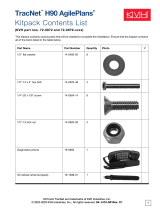
Tables 1-1 and 1-2 list the possible satellite pairs that may be
selected in Europe and in North America.
1-1
Introduction
54-0157 Rev. C
Astra 1
Astra 2N
Astra 2S
Hispasat
Hotbird
Sirius
Thor
Astra 1 Astra 2N Astra 2S Hispasat Hotbird Sirius Thor
Table 1-1
Available European Satellite Pairs
(European LNB Required)
TracVision L3’s default satellite
pairs are:
Europe: Astra 1 & Hotbird
N. America: DSS_101 & DSS_119
Refer to Section 2.4 for instructions
on selecting different satellites.

1.2 TracVision L3 System Overview
Your TracVision L3 employs a state-of-the-art actively stabilized
antenna system. Once the satellite is acquired, the antenna gyro
continuously measures your vehicle’s motion and position, and
transmits commands to the antenna motors to keep the antenna
pointed at the satellite at all times. A complete satellite TV system
includes the TracVision L3 connected to an IRD, and a television
set. A desktop or laptop computer is used to configure the system
for satellite selection and conduct diagnostics. The system is
illustrated in Figure 1-1.
1-2
A Guide to TracVision L3
Satellite Receiver 1
Options Purchased Separately
TV 1
TracVision L3 Antenna
Satellite Receiver 2TV 2 Laptop PC
Second TV
and receiver
option only
available with
U.S.-style,
dual output
LNB.
Figure 1-1
TracVision L3 System
Configuration
DSS_101
DSS_110*
DSS_119
Echo_61
Echo_110
Echo_119
Echo_148
Expressvu
DSS_101 DSS_110 DSS_119 Echo_61 Echo_110 Echo_119 Echo_148 Expressvu
* Contact KVH or DIRECTV for complete details on tracking and receiving signals from DSS_110.
Table 1-2
Available N. American Satellite
Pairs (U.S.-style LNB required)

System specifications and a functional block diagram are
provided in Appendices A and B, respectively.
1.2.1 TracVision L3 Components
The Antenna Unit includes the antenna positioning mechanism,
signal front end, power supply and control elements. The
antenna is a parabolic dish mounting a low noise block (LNB)
converter with built-in preamplifier. The European configuration
includes a single port LNB while the North American system
uses a dual-output LNB. A molded ABS radome encloses the
baseplate and is secured in place with standard fasteners. Liquid-
tight (watertight) fittings located on the back of the baseplate join
the power, signal, and control cabling from below-decks units.
1-3
Introduction
54-0157 Rev. C
Figure 1-2
Primary Components of the
TracVision L3
Always lift the Antenna Unit by the
gray baseplate and not the radome,
antenna reflector, or internal
mechanical assemblies.
NEVER pick up the unit by the
LNB or the gyro!

1.2.2 Integrated Receiver Decoder
The IRD (purchased separately) receives satellite signals from the
Antenna Unit for signal processing and channel selection, and
sends the signals to the TV set for viewing. The IRD also
provides the interface for the user to activate authorization for
reception. Please refer to the User’s Manual provided with your
selected IRD for complete operating instructions.
1.3 Materials Provided with
TracVision L3
Table 1-3 lists the units, cables, and materials packed in the
TracVision L3 package by name and KVH part number.
Component KVH Part No.
Antenna Unit (comprising): 01-0225-03
Baseplate Assembly 02-1044-01
Radome Assembly 02-0953-03
RF Cable 32-0589-30
Power Cable 32-0590-30
Antenna Data Cable 32-0630-30
PC Cable 32-0628-06
Mounting Plate 20-0668
Kitpack* 72-0101
Installation and Operation Manual 54-0157
IRD Ground Wire 32-0583-30
Switchplate 02-1023
* A complete listing of kitpack contents is provided in Section 2.2, “Mounting the
Antenna Unit.”
1-4
A Guide to TracVision L3
Table 1-3
TracVision L3 Packing List
Cables for the TracVision L3 are
stored beneath the Antenna Unit
during shipping.
The dual-output LNB in the North
American systems allows two
IRD/TV pairs to be connected
directly to the antenna.Three or
more pairs can be connected to the
system if an active multiswitch is
used. Section 2.3.6, “Connecting
the Antenna RF Signal Cable to the
IRD,” provides installation directions
for each of these options.

1.3.1 Additional Materials Required for
TracVision L3 Use
To make full use of your new TracVision L3 and receive satellite
TV on the road, you will need to provide/purchase the
following:
• Television
• Appropriate IRD for your selected satellite
TV service, and
• Sealing materials to weatherproof cable holes and
seal mounting plate.
1-5
Introduction
54-0157 Rev. C


2-1
Installation
54-0157 Rev. C
2 Installation
TracVision L3 is designed for simple installation and setup. Just
follow these easy steps:
Step Refer to Section...
1. Choose the hardware locations 2.1
2. Mount the Antenna Unit 2.2
3. Wire system components 2.3
4. Select active satellite 2.4
5. Set the skew angle (Europe only) 2.5
6. Check out system 2.6
7. Configure for remote dish use 2.7
Installation Tools and Materials Required
• Electric drill
•
3
⁄16" (5 mm) and
3
⁄32" (2 mm) drill bits and
1
⁄2" (13 mm) hole saw and auger bit
•
1
⁄
2" (13 mm) socket wrench
• #2 Phillips and #0 flat tip screwdrivers
• Augat Snap ‘n Seal Crimp/Strip Tool (Part
Number IT1000) if using the KVH-provided
F-connector
• Silicone sealant, RTV, or Sikaflex
• Thread locker (as required)
•
7
⁄16" (11 mm) open end wrench
• Wire strippers
• Construction adhesive (e.g., Liquid Nails)
• Rivet gun and
3
⁄
16" (5 mm) rivets (or other fastener
suitable for specific roof construction)
• PC with terminal emulation software such as
PROCOMM, Windows Terminal, or Windows
95/98 Hyperterminal
Plan the entire installation before
proceeding! Take into account
component placement, running
cable distances between units, and
accessibility to the equipment after
installation.
Table 2-1
Installation Process

2-2
A Guide to TracVision L3
2.1 Choosing the Best Location
• The ideal antenna site has a clear view of the
horizon/satellite all around.
• Keep the antenna clear of any obstructions on the
roof (e.g., air conditioners).
• Consider the location of the antenna relative to the
location of any equipment or necessary wiring
within the vehicle.
• For best operation, mount the antenna on a
horizontal surface.
2.2 Mounting the Antenna Unit
The following instructions will result in a secure, effective
installation and trouble-free operation of your TracVision L3.
Table 2-2 lists the materials provided in the TracVision L3
kitpack. Most of these components will be used in the installation
process.
Part Qty. KVH Part No.
RF F-Connector 1 23-0170
Tie-wrap 5 22-0013
Flash kit cable and adapter 1 02-1029
Antenna Mounting Procedure
1. Remove Antenna Unit from shipping container.
2. Remove and save 8 pan head screws and flat
washers that hold radome to baseplate. Carefully
lift radome straight up until clear of antenna
assembly and set aside.
3. Position Antenna Unit in desired location on the
centerline of the vehicle with baseplate and
mounting plate arrows facing in the same
direction (either forward or backward). The proper
orientation is illustrated in Figure 2-1 on the
following page.
Table 2-2
Kitpack Contents
Always lift the Antenna Unit by
the gray baseplate, never by the
radome or any portion of the
antenna assembly!
The liquid-tight connectors on
TracVision L3 may face either
forward or backward along the
centerline of the vehicle for more
convenient installation.

2-3
Installation
54-0157 Rev. C
4. While baseplate is in place, mark location(s) on
roof for cable access to permit convenient cable
access to the liquid-tight fittings on the back of the
baseplate.
5. Cut the tie-wraps holding the foam elevation
shipping restraint to the elevation axis motor shaft
(pictured in Figure 2-2) and remove the restraint.
6. Remove the three foam baseplate shipping
restraints securing the rotating plate, pictured in
Figure 2-3.
7. Remove six
1
⁄4-20 hex nuts and washers that secure
the Antenna Unit to the mounting plate.
8. Remove Antenna Unit from mounting plate.
9. The mounting plate allows the Antenna Unit to be
mounted on a curved roof. While the perimeter of
the mounting plate is secured to the vehicle with
Figure 2-1
Proper Orientation of
the Antenna Unit
Do not discard the foam shipping
restraints or shipping box. They
should be saved for future use in
case the Antenna Unit needs to be
removed and shipped to another
location.
Figure 2-3
Baseplate Shipping Restraints
Figure 2-2
Elevation Shipping Restraint

2-4
A Guide to TracVision L3
the appropriate fasteners, two flexible wings allow
the rear mounting bolts to attach to the antenna
baseplate. These may be angled upward to ensure
a secure mounting, as shown in Figure 2-4.
10. Using the mounting plate as a template, drill four
3
⁄
16" (5 mm)-holes through the roof of the vehicle at
each of the four corners. Temporarily secure the
mounting plate at the corners with rivets or
screws.
11. With the corners secured, use the mounting plate
as a template to mark and drill the remaining
nineteen
3
⁄16" (5 mm)-holes through the roof of the
vehicle. Remove plate and clean roof surface. The
dimensions of the baseplate and locations of the
drill holes are shown in Figure 2-5.
12. Place the construction adhesive over all holes. If
using a liquid construction adhesive, apply bead
to mounting plate in a zig-zag pattern.
Figure 2-4
Mounting the Unit on a
Curved Surface
Antenna Baseplate bolts to this “wing,”
which can remain horizontal.
Mounting
Plate Wing
Mounting Plate can be tightened down
to conform to a curved surface.
Figure 2-5
Baseplate Dimensions

2-5
Installation
54-0157 Rev. C
13. Reposition mounting plate over adhesive and
attach using
3
⁄16" (5 mm)-diameter rivets (or
appropriate fasteners). Seal all rivet heads and
edges with silicone.
14. Drill cable access hole(s) in vehicle.
15. When unit is installed with connectors facing the
rear of the vehicle, the drain holes are located as
shown in Figure 2-6.
Figure 2-6
Connectors Facing Rear
of Vehicle – Factory-drilled
Drain Hole Locations
Angle of Hole, relative to front
Angle of Hole, relative to front
Figure 2-7
Connectors Facing Front
of Vehicle – Recommended
Drain Hole Locations
You MUST drill out the drain holes
as indicated to ensure that any
moisture that enters the baseplate
is able to drain. Ensure that
factory-drilled holes are completely
sealed.
15a.(Alternate Drain Holes) If the Antenna Unit is
installed with the connectors facing the front of the
vehicle, drill out
3
⁄
16" (5 mm)-drain holes in rear-
facing side of baseplate as illustrated in Figure 2-7.
The existing factory-drilled drain holes shown in
Figure 2-6 must then be plugged with silicone
rubber sealant.
/