Page is loading ...

I
DSSSqsrem
Installation
TrainingFlanual

Foreword
This publication is intended to assist the installation technician installing the RCA brand DSS TM Digital
Satellite System. In this publication, basic installation techniques are covered for most common situations.
Included in each explanation is a suggested material and tool list. Also included is an overview of the DSS
System plus a signal flow description of the DSS receiver. This information is included to help the technician
install the system and explain its operation to their customers.
Safety Information!
DANGER Avoid Power Lines! When following the instruction in this guide to install and connect the
satellite antenna and connections, take extreme care to avoid contact with overhead power lines, lights, and
power circuits. Contact with these items may prove fatal.
Outdoor Dish Grounding: The outdoor dish used to receive satellite signals and the cable used to connect
the outdoor dish to the indoor receiving unit are required to comply with local installation codes and the
appropriate sections of the National Electrical Code (NEC), especially Article 810 and Article 820. These
codes require proper grounding of the metal structure of the outdoor dish and grounding of the connecting
cable at a point where it enters the house (or other building). The DSS System Installation Training Manual
contains instructions on how to install the system in compliance with the National Electrical Code (NEC).
If additional local installation codes apply, contact local inspection authorities.
Compliance with National Electrical and Local Codes: Before installing the Digital Satellite System,
check the electrical codes in your area.
Restrictions: Before installing the dish, check the zoning codes, covenants, and community restrictions in
your area. Some rules prohibit installing large satellite dishes, but may allow small ones. Also, there may
be restrictions in your area that limit the mounting height of dishes.
If you encounter homeowner or community restriction's, call 1-800-679-4776. Personnel at this number
can provide information that may be helpful when attempting to obtain permission to install the DSS Digital
Satellite System on the property.
* DSS and Digital Satellite System is an official trademark of DIRECTV, Inc., a unit of GM
Hughes Electronics.
Second Edition 9415 - First Printing
Copyright 1994
Thomson Consumer Electronics, Inc.
Trademark(s)® Registered Marca (s) Registrada(s)
Prepared by
Thomson Consumer Electronics, Inc.
Technical Training Department
10330 North Meridian St.
Indianapolis, Indiana 46290-1024

Table of Contents
Overview ................................................................................................................................... 5
Technical Overview ................................................................................................................. 10
Satellites ............................................................................................................................... 12
Dish ...................................................................................................................................... 14
Receiver Circuitry ................................................................................................................ 16
Diagnostics ........................................................................................................................... 17
Site Survey ................................................................................................................................ 22
Installation ................................................................................................................................ 32
Mounting the Dish ................................................................................................................ 32
Vertical Mounting Systems .................................................................................................. 42
Panel Siding ............................................................................................................................................. 42
Lap Siding ................................................................................................................................................. 46
Brick ......................................................................................................................................................... 52
Onder Block ............................................................................................................................................. 56
Horizontal Mounting Systems .............................................................................................. 63
Deck Railing ............................................................................................................................................. 63
Roof ..........................................................................................................................................................64
SpecialMounting Systems ...................................................................................................69
PoleMount ...............................................................................................................................................69
Chimney....................................................................................................................................................72
Dish Assembly .....................................................................................................................79
AssembletheDish.....................................................................................................................................79
InstalltheLNB Cable...............................................................................................................................81
InstalltheLNB ..........................................................................................................................................86
AttachingLNB CabletoReceiver.............................................................................................................88
TelephoneCableInstallation...................................................................................................................91
InstallingtheReceiver..........................................................................................................98
System Connections..................................................................................................................................I00
AligntheDish ......................................................................................................................105
DetermineAzimuthand Elevation............................................................................................................106
AdjustElevation........................................................................................................................................I07
AdjustAzimuth..........................................................................................................................................107
AcquiringSignal.......................................................................................................................................I09
Troubleshooting ....................................................................................................................... 114
APPENDICES
A. Finding DSS Azimuth and Elevation .............................................................................. 118
B. Using a Compass ............................................................................................................. 130
C. National Electrical Code .................................................................................................. 126
D. DSS Reference Publications ............................................................................................ 129
E. RCA DSS Dish Parts List ................................................................................................ 132
Glossary .................................................................................................................................... 133
Index ....................................................................................................................................... 136

Overview 5
Satellite Communication Basics
All comm_'cations services, from ship-to-shore communications, radio and television
to communications satellites are assigned unique bands of frequencies within the
electromagnetic spectrum in which to operate.
Overview
To receive signals from the earth successfully and relay them back again, satellites use
very high frequency radio waves operating in the microwave frequency bands--either
the C-band or KU-hand. C-band satellites generally transmit in the frequency band of
3.7 to4.2 Gigahertz (GHz), in what is known as the Fixed Satellite Service band orFSS.
However, these are the same frequencies occupied by ground-based point-to-point
communications, making C-band satellite reception more prone to interference.
KU-band satellites may be classified into two groups: low and medium power KU-band
satellites, transmitt'mg signals in the 11.7 to 12.2 GHz FSS band; and the new high-
power KU-band satellites transmiting in the 12.2 GHz to 12.7 GHz Direct Broadcast
Satellite service (DBS) band.
Unlike C-band satellites, these newer KU-band DBS satellites have exclusive rights to
the frequencies they occupy, and therefore have no microwave interference problems.
The RCA D SS System will receive programming from high-power KU-band satellites
operating in the DBS band.
Although C-band satellites are spaced 2° apart,high power KU-band satellites are
spaced 9° apart,and transmit at 120 ormore watts of power.
Because o ftheir lower frequency and transmitting power capabilities, C-band sate llites
require a large receiving dish, anywhere from 6 to 10 feet in diameter. The higher power
of KU-band satellites enables them to broadcast to a compact 18 inch diameter dish.
Satellite System
A satellite systemis made up of three basic dements:
• An uplink facility, which beams programming signals to satellites orbiting over the
equator.
• A satellite that receives the signals and re-transmits them hack to earth.
• A receiving station including the satellite dish.
The picture and sound information originating from astudio or broadcastfacility is first
sent to an uplink site, where it is processed and combined with other signals for
transmission on microwave frequencies. Next, a large uplink dish concentrates these
outgoing mierowave signals and beams them up to a satellite located 22,247 miles
above the equator. The satellite's receiving anteuna captures the incoming signals and
sends them to a receiver for further processing. These signals, which contain the
original picture and sound information, are converted to another group of microwave
frequencies, then sent to an amplifier for transmission back to earth. This whole
receiver/transmitter package is called a transponder. The outgoing signals from the
transponder are then reflected off a transmitting antenna, which focuses the micro-

6 Overview
waves into a beam of energy that is directed toward the earth. A satellite dish on the
ground collects the microwave energy containing the original picture and sound
information, and focuses that energy into a low noise block converter or LNB. The
LNB amplifies and converts the microwave signals to yet another lower group of
frequencies that can be sent via conventional coaxial cable to a satellite receiver-
decoder inside the user's house. The receiver tunes the individual transponders and
converts the original picture and sound information into video and audio signals that
can be seen and heard on a conventional television monitor and stereo system.
RCA DSS System
The RCA DSS System is a direct broadcast satellite system that enables millions of
viewers to receive many channels of high quality digital video programs fi,om anywhere
in the continental United States. The complete system transports digital data, video and
audio to the customer's home via high powered KU-band satellites. The program
provider sends its program material to an uplink site where the signal is digitally
encoded. The uplink site compresses the video and audio, encrypts the video and
formats the information into data "packets." The signal is transmitted to the DBS
satellites orbiting the earth at 22,247 miles above the equator at 101° west longitude.
The signal is then relayed back to earth and decoded by the customer's receiver. The
receiver connects to the customer's phone line and communicates with the subscription
service computer providing billing information (see figure 1).
R CA DSS Hardware
The two DSS packages are Basic and Deluxe.
Basic Package:
• Antenna (or Dish) with a single output dual polarity, Low Noise Block Converter
(LNB).
• Satellite Receiver.
• DSS/TV universalremote.
Basic
Package
DeluxePackage:
• SheetMoldedCompound(SMC)antennawith a twin outputdualpolarity LNB.
• SatelliteReceiver, incorporatingalowspeeddataport and additional audio/video
jacks
• A fullyuniversalremotethatcannotonly control the satellitereceiver, butalso
multiplebrandsoftelevisions,VCRsand cableboxes.
Themodel#DS1120RW(BasicPackage)includesaDRD102RWSatelliteReceiver,
#217095 (CRK91AI) Remote,and aDSA100RWAntenna/LNB).
DRD102R W Satellite Receiver
• Revolutionary compact design that blends in with other consumer eleca:onics
entertainment products.
• Color-coded jack panel facilitates system integration and provides easy hook-up.

Overview 7
_ TELUTE #1
UPLINK 5ffE
PHONEUNK_IA
IRDMOO_I
DDDDD
TELEPHONE UNE
PROGRAMPRO_IOER
Figure 1, Digital Satellite @stem

8 Overview
Connections include:
Satellite in: Provides direct connection from the satellite antenna/LNB.
In from Ant: Provides connection from an off-air antenna or cable feed.
Out to TV: Provides connection to antenna input of television.
S-VIDEO: Provides direct Y/C output to compatible televisions and VCRs.
Video, R/L Audio: Provides direct video and audio signals to television receivers,
VCRs and audio components.
Wideband Data Port: Enables reception of future services such as HDTV.
Phone: Provides connection to telephone line for program billing.
Indicators: LED on front panel that indicates "on" and blinks when there's a
message waiting.
• Local Controls: Eight buttons on the Satelfite Receiver's front panel allow full
operation of the satellite receiver, even without the remote control.
Access Card: A special card inserted into a slot on the receiver's front panel that
provides the means to track subscriber service requests and enable "turn-on" and
"turn-off" capability for subscription and pay-per-view events.
An electronic serial number unique to each card and satellite receiver enables the
Satellite Receiver to receive electronic messages from the communications center.
Messages are displayed on the television screen.
• 16x 9 widesereen formatcompatible: Processes panand scan commands fromthe
video data in a 16x 9broadcast, allowing the viewer to watch on a 4 x 3 television.
• Program Guide displays an electronically updated matrix of currentand future
programs sortedby service and time.
The system also supports specific guides, such as pay-per-view, sent by program
providers.
• Additional capabilities include the ability to display individual categories of
programming such as sports,news, movies, music, etc.
Favorite (Multiple) Channellists provideeasy selection of all orupto two favorite
groups of channels when utilizing the channel up/down buttons.
Alternate audio selection capability provides access to any of the audio channels
associated with each video channel. For example, foreign language audio may be
available for certain programs.
User Locks allow you to limit access to certain features, channels, select the rating
limit of the system and to password-protect this limit with a four-digit PIN
(Personal Identification Number).

Overview 9
Additional Menus provide:
Dish positioning and adjustment.
Diagnostics.
Access to help screens.
Ability to set-up and customize operation.
Review/cancel purchases and services.
# 217095 (CRK91A1) Infrared Remote Control
• 30-button keypad.
• Ergonomicdesign.
• Provides complete satellite receiver operation.
• Large color-coded buttons are clearly identified for easy operation.
• Pre-programmed codes control the primary functions of most television brands
manufactured after 1984 utilizing infrared technology.
DSA100R W Antenna/LNB
• Small 18" parabolic reflector is lightweight and inconspicuous.
• Installation task is similar to "off-air" antenna.
• Designed to be easily mounted to the side of ahome, deck rail, roof or chirrmey that
provides an unobstructed view of the 101oWest longitude position pointing toward
Texas.
The model DS2430RW Deluxe Package includes a DRD203RW satellite receiver,
#217094 (CRK91B 1) remote and a DSA400RW antenna/LNB.
DRD203RW Satellite Receiver
Includes all of the features of the DRD102RW plus:
• Second pair of AN jacks on Satellite Receiver.
• Computer serial port for downloading data.
# 217094 (CRK91B1) Infrared Remote Control
Includes all of the features of the # 217095 remote with the following upgrades:
• 39-button keypad.
• Preprogrammedto controltheprimary functions ofmostmanufacturers' brands of
televisions, VCRs, laserdisc players and cable boxes utilizing infrared technology.
DSA4OOR W Antenna/LNB
Includes all of the features of the DSA200RW with the following upgrades/additions:
• Sheet molded compound (SMC) reflector-- more durable than metal.
• Antenna/LNB developed with twin outputs capable of operating two or more
compatible satellite receivers.
Deluxe
Package

10 OverviewTechnical
Technical
Overview
Uplink
The DSS System transports digital data, video and audio to the customer's home via
a high powered KU-band satellite. The program provider sends its program material
to the uplink site where the signal is digitally encoded. The "uplink" is the portion of
the signal transmitted from the earth to the satellite. The uplink site compresses the
video and audio, encrypts the video and formats the information into data "packets"
that are transmitted. The signal is transmitted to a satellite where it is relayed back to
the earth and decoded by the customer's receiver.
MPEG2 Compression
The video and audio signals are transmitted as digital signals instead of conventional
analog. The amount of data required to code all the video and audio information
would require a transfer rate well into the hundreds ofMbps (Mega-bits per second).
This is too large and impractical a data rate to be processed in a cost effective way with
current hardware. In order to minimize the data transfer rate, the data is compressed
using MPEG2 compression. MPEG (Motion Pictures Expert Group) is an organiza-
tion who has developed a specification for transportation of moving images over
communication data networks. Fundamentally, the system is based on the principle
that images contain a lot of redundancy from one frame of video to another - the
background stays the same for many frames at a time. Compression is accomplished
by predicting motion that occurs from one frame of video to another and transmitting
motion vectors and background information. By coding only the motion and
background difference instead of the entire frame of video information, the effective
video data rate can be reduced from hundreds of Mbps to an average of 3 to 6 Mbps.
This data rate is dynamic and will change depending on the amount of motion
occurring in the video.
In addition to MPEG video compression, MPEG audio compression is also used to
reduce the audio data rate. Audio compression is accomplished by eliminating soft
sounds that are near loud sounds in the fi'equency domain. The compressed audio data
rate can vary from 56 Kbs (Kilo-bits per second) on mono signals to 384 Kbps on
stereo signals.
Data Encryption
To prevent unauthorized signal reception, the video signal is encrypted (scrambled)
at the uplink site. A secure encryption "algorithm" or formula know as the Digital
Encryption Standard (DES) is used to encode the video information. The keys for
decoding the data are transmitted in the data packets. The customer's Access Card
decrypts the keys which allows the receiver to decode the data. When a Access Card
is activated in a receiver for the first time, the serial number of the receiver is encoded
on the Access Card. This prevents the Access Card from activating any other receiver
except the one in which it was initially authorized. The receiver will notfunction with
the Access Card removed.
Data Packets
The program information is completely digital and is transmitted in data "packets."
This concept is very similar to data transferred by a computer over a modem. Five

Technical Overview 11
different types of data packets are Video, Audio, CA, PC compatible serial data and
Program Guide. Video and audio packets contain the visual and audio information of
the program. The CA (Conditional Access) packet contains information that is
addressed to individual receivers. This includes customer E-Mall, Access Card
activation information and which channels the receiver is authorized to decode. PC
compatible serial data packets can contain any form of data the program provider
wants to transmit, such as stock reports or software. The Program Guide maps the
channel numbers to transponders and SCID's (more on this later). It also gives the
customer TV program listing information.
Figure 2 shows a typical uplink configuration for one transponder. In the past, a single
transponder was used for a single satellite channel. With digital signals, more than one
satellite channel can be sent on the same transponder. The example shows three video
channels, five stereo audio channels (one for each video channel plus two extra for
other services such as a second language), and a PC compatible data channel. Audio
and video signals from the program provider are encoded and converted to data
packets. The configurations can vary depending on the type of programming. The
data packets are then multiplexed into serial data and sent to the transmitter.
PT......L
!
Data
,t_tlosl ,.at.at..t.,
8CI0
Program
Progrul Guidw iltlkos the
cltei_nel numbers Io
trenspcmders ar,d
8C10_. It dso _S
_r PmO'm Ibtir_
,F 3
,E 3--
licit
_ €_¢waa ma_ra
_ CA _ Null Data Vldee I_11 Alldle
Figure 2, Uplink

12 Technical Overview
Each data packet is 147 bytes long. The firsttwo bytes (a byte is made up of 8 bits)
of information contain the SCID and Flags. The SCID (Service Channel ID) is a
unique 12bit number from0to 4095 that uniquely identifies the packet's datachannel.
The Flags are made up of 4 bits used primarily to control whether or not the packet is
encrypted and which key to use. The third byte of information is made up ofa 4 bit
Packet Type indicator and a 4 bit Continuity Counter. The Packet Type identifies the
packet as one of four data types. When combined with the SCID, the Packet Type
determ'mes how the packet is to beused. TheContinuity Counter increments once for
each Packet Type and SCID. The next 127 bytes of information consists of the
"payload" datawhich isthe actual usable information sentfromthe program provider.
(See figure 3.)
Satellites
2 BYT_.S 1BYTE
,=, BYTES I 17 BYTES I
I I PAYLON) FORWARDERROR
SCID & FLAGS PACKETTYPE& CORRECTION
CONTINUITYCOUNTER
Figure 3, Data Packet
Two high power KU-band satellites provide the DSS signal for the receiver. The
satellites arelocated inageostationary orbitin the "Clarke" belt, 22,247 miles above
the equator. They are positioned less than .5° apartfrom each other with the center
between them at 101° W. longitude. This permits afixed antenna to be pointed at the
101° slot and receive signals from both satellites. The downlink frequency is in the
K4 part of the KU-band at 12.2 GHz to 12.7 GHz. The total transponder channel
bandwidth is 24 MHz per channel with channel spacing at 14.58 MHz. Each satellite
has sixteen 120 watt transponders. The satellites have a life expectancy of 12
years.(See figure 5.)
Unlike C-band satellites that use horizontal and vertical polarization, the DSS
satellites use circular polarization. The microwave energy is transmitted in a spiral-
like pattern. The direction of rotation determines the type of circular polarization
(Figure 4). In the DSS System, one satellite is configured foronly right-handcircular
polarized transpondersand the otheris configured for only left-hand circularpolar-
ized transponders. This nets 32 total transponders between two sateliites.
RightHandCircularlyPoladzedWave LeftHandCircularlyPoladzedWave
Figure 4, Right-hand and Left-hand Circular Polarization

Technical Overview 13
LONGITUDE
101°
I
UPHNK SITE
DDDDD
OOOOO
TELEPHONEMNE,
PROGRAMPRO_DER
Figure 5, Digital Satellite System

14 Technical Overview
Although there areonly 16transponders per satellite, the channel capabilities arefar
greater. Using datacompression andmultiplexing, the two satellites workingtogether
have the possibility of carrying over 150 conventional (non-HDTV) audio and video
channels via 32 transponders.
Dish
The"dish" is an 18 inch, slightly oval shaped KU-band antenna. The slight oval shape
is due to the 22.5 ° offset feed of the LNB (Low Noise Block converter), figure 6. The
offset feed positions the LNB out of the way so it does not block any surface area of
the dish, preventing attenuation of the incoming microwave signal.
0
Figure 6, Satellite Dish

Technical Overview 15
LNB
The LNB converts the 12.2 GHz to 12.7 GHz downlink signal fi'om the satellites to
the 950 MHz to 1450 MI-Iz signal required by the receiver tuner. Two types of LNB's
are available - dual and single output. The single output LNB has only one RF
connector while the dual output LNB has two, figure 7. The dual output LNB can be
used to feed a second receiver or other form of distribution system. TheBasic package
comes with the single output LNB. The Deluxe package comes with the dual output
LNB.
SINGLE OUTPUT LNB
DUAL OUTPUT LNB
Figure 7, Single and Dual output LNB's
Both types of LNB's can receive both left and fight-hand polarized signals. Polariza-
tion is selected electrically via a DC voltage sent on the center conductor of the cable
from the receiver. Right-hand polarization is selected with +13 volts and left-hand
polarization is selected with +17 volts.

16 Technical Overview
Receiver
Circuitw
The receiver is a complex digital signal processor. The amount and speed of data the
receiver processes rivals even the faster personal computers on the market today. The
information received from the satellite is a digital signal that is decoded and digitally
processed. There are no analog signals to be found except for those exiting the NTSC
video encoder and the audio DAC (Digital to Analog Converter).
The downlink signal from the satellite is downconverted from 12.7 - 12.2 GHz to 950
- 1450 MHz by the LNB (Low Noise Block) converter. The tuner then isolates a single
digitally modulated 24 MHz transponder. The demodulator converts the modulated
data to a digital data stream.
The data is encoded at the transmitter site by a process that enables the decoder to
reassemble the data and verify and correct errors that may have occurred during
transmission. This process is called Forward ErrorCorrection (FEe). The error
corrected data is output to the transport IC via an 8-bit parallel interface.
The transport IC is the heart of the receiver data processing circuitry. Data from the
FEC block is processed by the transport IC and sent to respective audio and video
decoders. The microprocessor communicates with the audio and video decoders
through the transport IC. The access card interface is also processed through the
transport IC.
SATELLITE
LN.A ,:,:_1 TONO_MOOou,M,N'_C I I.CCE.C'_OI
OUT I I
21...... I I , , i
...... --" ' '& -- DATA DATA /
_D.?.o._._ T wcL./ I
TOPHONE TIP _ / T I
/I
.I I I / .I. o--.I " I
"1 1 I I -I i i
L i l i ID A O
°iII If
Co_CR_
', I I---I k _o I I ,uo_AM......I
I PROCESSORII_oEor--I.,E. I I MPEGI P£.=."I
I Ro. I I" Ho "= I I _ °l'-'l-" I
I I I I I c.K OATA I 1 CtK_TA , _ ==,rN-..,
I sc, _ t _ T _ :".... _,_
I so* l 'I NTSGENCODER, I I I I I'_mJ_.RFI N
( B SYNC, ANTI-TAPE, DUAL AUDIO :
,_s_,,,, I _ ...k._.o_.,.c..[I .._c...l.,I'F'°°=,,o,,
T IE_,,o.Ir "_ _ " _W
I _o,_. I ' ' _ _ :1.
I _cE_,_ I w ,:,
OUTDOOR UN_
................................
TRANSPORT IC
TO PHONE -_
CONTROLLER
DIGITAL _NJkl.
_O_/IR
SVIDEO VIDEO
OUT OUT R OUT L OUT
Figure 8, Receiver Block Diagram

Technical Overview 17
The Access Card receives the encrypted keys for decoding a scrambled channel from
the transport IC. The Access Card deerypts the keys and stores them in a register in
the transport IC. The transport IC uses the keys to decode the data. The Access Card
also handles the tracking and billing for these services
Video data is processed by the MPEG video decoder. This IC decodes the compressed
video data and sends it to the NTSC encoder. The encoder converts the digital video
information into NTSC analog video that is output to the S-Video and standard
composite video output jacks.
Audio data is likewise decoded by the MPEG audio decoder. The decoded 16-bit
stereo audio data is sent to the dual DAC (Digital to Analog Converter) where the left
and right audio channel data are separated and converted back into stereo analog
audio. The audio is output to the left and right audio jacks and is also mixed together
to provide a mono audio source for the RF converter.
The microprocessor receives and decodes IR remote commands and front keyboard
commands. Its program software is contained in the processor ROM (Read Only
Memory). The microprocessor controls the other digital devices of the receiver via
address and data lines. It is responsible for turning on the green LED on the ON/OFF
button.
The modem connects to the customer's phone line and calls the program provider and
transmits the customers programpurchas.es for billing purposes. The modem operates
at 1200 bps and is controlled by the microprocessor. When the modem first attempts
to dial, it sends the first number as touch-tone. If the dial tone continues after the first
number, the modems switches to pulse dialing and redials the entire number. If the
dial tone stops after the first number, the modem continues to dial the rest of the
number as a touch-tone number. The modem also automatically releases the phone
line if the customer picks up another phone on the same extension.
Thereeeivercontainstwodiagnostictestmenus. ThefirsttestisacustomercontroUed Diagnostics
menu that checks the signal, tuning, phone connection and access card. The second
test menu is servicer controlled. It checks the majority of the receiver for problems.
Customer Controlled Diagnostics
The customer controlled test helps the customer during installation or any time the
receiver appears not to function properly.
Signal test:
Tuning test:
Phone test:
Access card test:
Cheeks the value of error bit number and the error rate to determine
if the antenna connections are properly installed.
Checks to insure a transponder can be tuned. Thetestis eousidered
successful and this part of the test is halted if proper tuning occurs
on 1 of the 32 transponders.
The phone test checks for dial tone and performs an internal
loopbaek test.
Sends a message to the access card and cheeks for a valid reply.

18 Technical Overview
The response for all tests will be an "OK" display or an appropriate message
informing the customer the general area of the problem.
To enter the System Test feature:
Select "Options" from the "DSS Main Menu. '"
DSS Main Menu
Fmedrl k e_l_er mP_em h m
1Pe_eu_
2Aeltadlor_l
I 4opqn
S_mlwfehJdlo
et_'W
OE5_
!
I 4 P_w_h_dutMp yo_ I
Figure 9, Main Menu
Select "Setup" from the "Options" menu.
_wnn_k
RNm
s LadL unl_ andGwld IJm
IS_p
Ol_lt
Is 8_w_DIS_
Figure 10, Options Menu

Technical Overview 19
Select "'System Test" from the "Setup "'menu.
1_ Dil_ P01flllng
3 IndJl A_em C_d
4 PiO_e S_e
0Bdt
I Deim1"_dJyo_D_D_il_mm_l_. J
Figure 11, Setup Menu
Select "'Test" from the "System Test'" menu.
_om Tost
T_ _ _ a_JGT.
_ t]mmM m _ m N lk_ MWsJ.
N_IN
Figure 12, System Test Menu
The system test results are displayed automatically wben the test is complete. The
following two screens show whether the receiver passed orfailed the test. If the access
card passes the test, the access card ID number will be displayed in the window.
_Teet Results
aml imlm allJlO1".
G_t_ _14_mdm
llhl:l_l:
Ohukl_omm
mcll_
G'mckm cml U
_Te_ Results
md_im IIELECT,
OK
OK
_orM_
OK
_Camk
OK
Figure 13, System Test Results

Technical Overview
ServicerControlledDiagnostics
The servicer controlled test provides a more in-depth analysis of the receiver for
proper operation. The test pattern checks all possible connections between compo-
nents as a troubleshooting aid. The following information is provided to the servicer:
1. IRD serial number
2. Demodulator vendor & version number
3. Signal Strength
4. ROM checksum results
5. SRAM test results
6. V-Ram test results
7. Telco callback results
8. Verifier Version
9. Access Card Test & Serial Number
10. IRD ROM version
11. EEprom test results
The response for all tests will indicate the test was successful or not successful.
In addition, this menu will allow entry into the phone prefix menu so the installer can
set up a one digit phone prefix.
To Enter the Service -Test Feature:
Simultaneously press the front panel"TV/DSS" and the "DOWN" arrow button. The
following screen will appear.
$etvl_ TNt
IRD _I¢_K4FF
RDM I_1111 I
V-DramTea
VJlIWOM4 I_G0
mill1 117
iiiiiiiiii i i
i iii ii
IllamW 07m
HHIHIH
PhonoF_f_
le_em_m_F_x _m_
es_l _ ol( et_ _ gim_'T.
E3
l_st l.o_ _sra _t lo pl a _ _ lm
Figure 14, Service Test Menu
The test results are automatically displayed after the test is complete. The servicer
is given the option to exit or run the test again.

Technical Overview 21
IOFF
MESSAGE
A
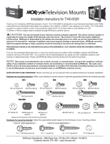
Figure 15, Front Panel Buttons
Also included in the Service Test Menu are previsions for testing the modem and
setting a single digit prefix number. During the service test, the modem will dial the
phone number that appears in the boxes at the top of the test menu. The phone number
earl be changed by using the "DOWN" arrow keys on the remote control or receiver
to move the cursor past the "Prefix" prompt to the number boxes. Once the boxes are
selected, the number can be entered or changed with the number keys on the remote
or by using the "UP"/DOWN" keys on the remote or the receiver. The prefix can be
changed by selecting "Phone Prefix" on the display and changing the number with the
number keys on the remote control or by using the arrow keys on the remote control
and front panel.
/