Page is loading ...

Satellite Television
KVHTracVision
®
4
technical
manual
•
Installation
•
Configuration
•
Maintenance
A Guide to TracVision 4

1
TracVision 4 Installation and Technical Manual – ADDENDUM
54-0150 Addendum to Rev. E
TracVision 4 Technical
Manual Addendum
(ECO #5416)
The following information applies to Revision E of the
TracVision 4 Installation and Technical Manual (KVH Part
Number 54-0150).
Appendix E
Predefined Satellite
Configurations
Some minor corrections have been made to the table of predefined
satellite configurations for European satellites (corrections are noted in
bold type). The North American satellite data remains unchanged.
As noted previously, your TracVision 4 comes programmed with
the satellite configurations for seven European and seven North
American satellite services. For your reference, those
configurations are listed below. These configurations are current
as of July 1, 2001, and are subject to change by the satellite
service providers.

2
European Satellites
Satellite F,S,C,ID,P,B,D
Astra 1 11778,27500,34,0x0020,V,H,3
11742,27500,34,0x0020,V,L,3
12344,27500,34,0x0035,H,H,3
11876,27500,34,0x0020,H,L,3
Astra 2N 11778,27500,23,0x0020,V,H,3
00000,27500,34,0x0000,V,L,3
11914,27500,23,0x0020,H,H,3
00000,27500,34,0x0000,H,L,3
Astra 2S 11817,27500,23,0x0020,V,H,3
00000,27500,34,0x0000,V,L,3
11798,27500,23,0x0020,H,H,3
00000,27500,34,0x0000,H,L,3
Hispasat 12152,27500,34,0x0031,V,H,3
11660,27500,34,0x0031,V,L,3
12154,27500,34,0x0031,H,H,3
11522,27500,34,0x0031,H,L,3
Hotbird 12073,27500,34,0x013E,V,H,3
11958,27500,34,0x013E,V,L,3
11862,27500,34,0x013E,H,H,3
11862,27500,34,0x013E,H,L,3
Sirius 12130,27500,34,0x03E8,V,H,3
00000,27500,34,0x0000,V,L,3
12108,27500,34,0x0001,H,H,3
00000,27500,34,0x0000,H,L,3
Thor 12226,28000,78,0x0046,V,H,3
11309,24500,78,0x0046,V,L,3
12322,27800,34,0x0046,H,H,3
11229,24500,78,0x0046,H,L,3
Configuration Definitions
F = Frequency
S = Transponder symbol rate
C = FEC code
ID = Satellite network ID
P = LNB polarization (vertical or
horizontal)
B = LNB band (high, low, or USA)
D = Decoding type (3 = DVB)

54-0150 Rev. E
TracVision 4 Installation and
Technical Manual
This manual provides detailed instructions on the proper
installation, use, and maintenance of the KVH TracVision 4
automatic satellite tracking system.
Throughout this manual, important information is marked for
your attention by these icons:
Direct questions, comments, or suggestions to:
KVH Industries, Inc. KVH Europe A/S
50 Enterprise Center Ved Klaedebo 12
Middletown, RI 02842 USA 2970 Hoersholm Denmark
tel: +1 401 847-3327 tel: +45 45 16 01 80
fax: +1 401 849-0045 fax: +45 45 86 70 77
Internet: www.kvh.com Internet: www.kvh.com
KVH Part # 54-0150 Rev. E
© 2001, KVH Industries, Inc.
TracVision 4 Serial Number
This serial number will be required
for all troubleshooting or service
calls made regarding this product.

TracVision
®
and KVH
®
are registered trademarks
of KVH Industries, Inc.
DIRECTV
®
is an official trademark of DIRECTV, Inc.,
a unit of GM Hughes Electronics.
DISH Network
™
is an official trademark of
EchoStar Communications Corporation.
ExpressVu is a property of Bell ExpressVu, a wholly owned
subsidiary of Bell Satellite Services.

i
54-0150 Rev. E
Table of Contents
1 TracVision 4 System Overview . . . . . . . . . . . . . . . . . . .1-1
1.1 Materials Provided With TracVision 4 System . . . . . . . . . . . . . .1-1
2 Installation . . . . . . . . . . . . . . . . . . . . . . . . . . . . . . . .2-1
2.1 Choosing the Best Location and Getting
the Best Reception . . . . . . . . . . . . . . . . . . . . . . . . . . . . . . . . . . .2-2
2.2 Installing the Antenna Unit . . . . . . . . . . . . . . . . . . . . . . . . . . . . .2-2
2.2.1 Setting the Skew Angle (European Systems Only) . . . . . . .2-6
2.3 Wiring the TracVision 4 System . . . . . . . . . . . . . . . . . . . . . . . . .2-6
2.3.1 Wiring the Antenna Unit Data Cable . . . . . . . . . . . . . . . . . .2-8
2.3.2 Wiring the Antenna Unit Power Cable . . . . . . . . . . . . . . . . .2-8
2.3.3 Connecting to Ship’s Power . . . . . . . . . . . . . . . . . . . . . . . .2-9
2.3.4 IRD Ground Cable . . . . . . . . . . . . . . . . . . . . . . . . . . . . . . .2-9
2.3.5 Installing the Switchplate . . . . . . . . . . . . . . . . . . . . . . . . .2-10
2.3.6 Connecting an Antenna RF Signal Cable to the IRD . . . . .2-10
2.3.6.1 Connecting the Antenna RF Signal Cables
to a Multiswitch (North American
Systems Only) . . . . . . . . . . . . . . . . . . . . . . . . . . . . . . .2-11
2.4 Commissioning the IRD . . . . . . . . . . . . . . . . . . . . . . . . . . . . . .2-13
2.5 Selecting the Active Satellite . . . . . . . . . . . . . . . . . . . . . . . . . .2-14
2.5.1 Installing Your Selected Satellites . . . . . . . . . . . . . . . . . . .2-15
2.5.2 Programming User-defined Satellites . . . . . . . . . . . . . . . .2-16
2.6 Checking Out the System . . . . . . . . . . . . . . . . . . . . . . . . . . . . .2-20
3 Troubleshooting . . . . . . . . . . . . . . . . . . . . . . . . . . . . .3-1
3.1 Causes and Remedies for Common Operational Issues . . . . . .3-1
3.1.1 Blown Fuse, Low Power, or Wiring . . . . . . . . . . . . . . . . . . .3-2
3.1.2 Vessel Turning During Startup . . . . . . . . . . . . . . . . . . . . . . .3-2
3.1.3 Incorrect Satellite Configuration
(European Systems Only) . . . . . . . . . . . . . . . . . . . . . . . . . .3-2
3.1.4 Satellite Signal Blocked . . . . . . . . . . . . . . . . . . . . . . . . . . .3-3

3.1.5 Outside Satellite Coverage Zone . . . . . . . . . . . . . . . . . . . .3-3
3.1.6 Radar Interference . . . . . . . . . . . . . . . . . . . . . . . . . . . . . . .3-3
3.1.7 Incorrect or Loose RF Connectors . . . . . . . . . . . . . . . . . . .3-3
3.1.8 Multiswitch Interference (DSS Plus™ IRD Users Only) . . . .3-3
3.1.9 Passive Multiswitch Used (North American
Systems Only) . . . . . . . . . . . . . . . . . . . . . . . . . . . . . . . . . .3-4
3.2 IRD Troubleshooting . . . . . . . . . . . . . . . . . . . . . . . . . . . . . . . . . .3-4
3.3 Antenna Gyro and LNB Faults . . . . . . . . . . . . . . . . . . . . . . . . . .3-4
3.4 Computer Diagnostics . . . . . . . . . . . . . . . . . . . . . . . . . . . . . . . .3-4
3.5 Maintenance Port Parser Commands . . . . . . . . . . . . . . . . . . . . .3-5
4 Maintenance . . . . . . . . . . . . . . . . . . . . . . . . . . . . . . .4-1
4.1 Warranty/Service Information . . . . . . . . . . . . . . . . . . . . . . . . . . .4-1
4.2 Preventive Maintenance . . . . . . . . . . . . . . . . . . . . . . . . . . . . . . .4-1
4.3 TracVision 4 Field Replaceable Units . . . . . . . . . . . . . . . . . . . . .4-2
4.4 PCB Removal and Replacement . . . . . . . . . . . . . . . . . . . . . . . . .4-4
4.4.1 CPU Board . . . . . . . . . . . . . . . . . . . . . . . . . . . . . . . . . . . . .4-5
4.4.2 RF Detector . . . . . . . . . . . . . . . . . . . . . . . . . . . . . . . . . . . .4-5
4.5 Antenna Gyro Assembly . . . . . . . . . . . . . . . . . . . . . . . . . . . . . . .4-7
4.6 Elevation Motor and Belt Replacement . . . . . . . . . . . . . . . . . . .4-9
4.6.1 Drive Belt Removal and Replacement . . . . . . . . . . . . . . . . .4-9
4.6.2 Elevation Drive Motor Removal and Replacement . . . . . . .4-10
4.7 Antenna LNB Replacement . . . . . . . . . . . . . . . . . . . . . . . . . . . .4-11
4.7.1 European LNB Replacement . . . . . . . . . . . . . . . . . . . . . .4-11
4.7.2 U.S.-style LNB Replacement . . . . . . . . . . . . . . . . . . . . . . .4-11
4.8 Preparation for Shipment . . . . . . . . . . . . . . . . . . . . . . . . . . . . .4-12
Appendix A System Specifications . . . . . . . . . . . . . . . . . .A-1
A.1 Antenna Specifications . . . . . . . . . . . . . . . . . . . . . . . . . . . . . . .A-1
Appendix B TracVision 4 Baseplate Mounting
Holes Template . . . . . . . . . . . . . . . . . . . . . . .B-1
Appendix C Switchplate Template . . . . . . . . . . . . . . . . . .C-1
ii

Appendix D Comprehensive TracVision 4
System Wiring Diagram . . . . . . . . . . . . . . . . .D-1
Appendix E Predefined Satellite Configurations . . . . . . . . .E-1
Appendix F Startup Data Sequences . . . . . . . . . . . . . . . . .F-1
Appendix G Maintenance Port Parser Commands . . . . . . . .G-1
G.1 System Commands . . . . . . . . . . . . . . . . . . . . . . . . . . . . . . . . . .G-1
G.2 Manual Positioning Commands . . . . . . . . . . . . . . . . . . . . . . . . .G-2
G.3 Operational Commands . . . . . . . . . . . . . . . . . . . . . . . . . . . . . . .G-3
G.4 Tracking and Conical Scan Commands . . . . . . . . . . . . . . . . . . .G-4
G.5 RF Board Commands . . . . . . . . . . . . . . . . . . . . . . . . . . . . . . . . .G-5
G.6 Installation Commands . . . . . . . . . . . . . . . . . . . . . . . . . . . . . . .G-7
G.7 Debug Commands . . . . . . . . . . . . . . . . . . . . . . . . . . . . . . . . . . .G-8
List of Figures
Figure 1-1 TracVision 4 System Configuration . . . . . . . . . . . . . . . . . .1-1
Figure 2-1 Antenna Unit Dimensions . . . . . . . . . . . . . . . . . . . . . . . . .2-4
Figure 2-2 Baseplate/Foam Seal Orientation (Bottom View) . . . . . . . .2-4
Figure 2-3 Baseplate Connector Assignments . . . . . . . . . . . . . . . . . .2-5
Figure 2-4 Bolting the Antenna Unit to the Deck (Side View) . . . . . . .2-5
Figure 2-5 Adjusting the European LNB Skew Angle . . . . . . . . . . . . .2-6
Figure 2-6 Skew Angle Labels . . . . . . . . . . . . . . . . . . . . . . . . . . . . . .2-6
Figure 2-7 Switchplate Panel Cutout Dimensions . . . . . . . . . . . . . . . .2-7
Figure 2-8 Correctly Securing Wires within the
Switchplate Connectors . . . . . . . . . . . . . . . . . . . . . . . . . .2-7
Figure 2-9 Data Cable Wiring Arrangement . . . . . . . . . . . . . . . . . . . .2-8
Figure 2-10 Wiring the Antenna Unit Power Cable
and Indicator Lamp . . . . . . . . . . . . . . . . . . . . . . . . . . . . .2-9
Figure 2-11 Wiring the Switchplate to Ship’s Power . . . . . . . . . . . . . . .2-9
Figure 2-12 Mounting the Switchplate Support Frame
and Front Cover . . . . . . . . . . . . . . . . . . . . . . . . . . . . . . .2-10
iii
54-0150 Rev. E

Figure 2-13 Single Multiswitch Installation (North
American Systems Only) . . . . . . . . . . . . . . . . . . . . . . . .2-12
Figure 2-14 Multiple Multiswitch Installation (North
American Systems Only) . . . . . . . . . . . . . . . . . . . . . . . .2-12
Figure 3-1 Troubleshooting Matrix . . . . . . . . . . . . . . . . . . . . . . . . . . .3-1
Figure 3-2 DB9 Connector . . . . . . . . . . . . . . . . . . . . . . . . . . . . . . . .3-5
Figure 4-1 TracVision 4 Antenna Unit (Baseplate Cut Away) . . . . . . .4-3
Figure 4-2 PCB Cover Plate Removal . . . . . . . . . . . . . . . . . . . . . . . .4-4
Figure 4-3 PCB Connector Locations (Rear View) . . . . . . . . . . . . . . .4-4
Figure 4-4 PCB Mounting (Top View) . . . . . . . . . . . . . . . . . . . . . . . . .4-5
Figure 4-5 Data and RF Flash Cables . . . . . . . . . . . . . . . . . . . . . . . .4-5
Figure 4-6 RF Cable Ferrules . . . . . . . . . . . . . . . . . . . . . . . . . . . . . .4-6
Figure 4-7 New RF Board Installation . . . . . . . . . . . . . . . . . . . . . . . .4-6
Figure 4-8 Elevation Drive Mechanism . . . . . . . . . . . . . . . . . . . . . . .4-9
Figure 4-9 European LNB Removal . . . . . . . . . . . . . . . . . . . . . . . . .4-11
Figure 4-10 U.S.-style LNB Removal . . . . . . . . . . . . . . . . . . . . . . . . .4-11
Figure 4-11 Shipping Restraint Placement . . . . . . . . . . . . . . . . . . . . .4-12
List of Tables
Table 1-1 TracVision 4 Packing List . . . . . . . . . . . . . . . . . . . . . . . .1-1
Table 2-1 Installation Process . . . . . . . . . . . . . . . . . . . . . . . . . . . .2-1
Table 2-2 Lengths of Provided Below-decks Cables . . . . . . . . . . .2-2
Table 2-3 Antenna Unit Kitpack Contents . . . . . . . . . . . . . . . . . . .2-3
Table 2-4 Key IRD Settings . . . . . . . . . . . . . . . . . . . . . . . . . . . . .2-13
Table 2-5 Available Satellite Pairs – Europe
(European LNB required) . . . . . . . . . . . . . . . . . . . . . .2-14
Table 2-6 Available Satellite Pairs – North America
(U.S.-style LNB required) . . . . . . . . . . . . . . . . . . . . . . .2-14
Table 2-7 SATCONFIG Parser Command . . . . . . . . . . . . . . . . . .2-17
Table 2-8 Satellite Transponder Data Sequence . . . . . . . . . . . . .2-18
Table 2-9 Satellite Transponder Default Data . . . . . . . . . . . . . . . .2-18
Table 2-10 Sample Satellite Configuration Data . . . . . . . . . . . . . .2-19
iv

Table 4-1 TracVision 4 Field Replaceable Units . . . . . . . . . . . . . . .4-2
Table A-1 TracVision 4 Antenna Physical Specifications . . . . . . . .A-1
Table A-2 TracVision 4 Power Specifications . . . . . . . . . . . . . . . . .A-1
Table A-3 TracVision 4 Performance Specifications . . . . . . . . . . . .A-1
Table G-1 System Commands . . . . . . . . . . . . . . . . . . . . . . . . . . .G-1
Table G-2 Manual Positioning Commands . . . . . . . . . . . . . . . . . . .G-2
Table G-3 Operational Commands . . . . . . . . . . . . . . . . . . . . . . . .G-3
Table G-4 Tracking and Conical Scan Commands . . . . . . . . . . . . .G-4
Table G-5 RF Board Commands . . . . . . . . . . . . . . . . . . . . . . . . . .G-5
Table G-6 Installation Commands . . . . . . . . . . . . . . . . . . . . . . . . .G-7
Table G-7 Debug Commands . . . . . . . . . . . . . . . . . . . . . . . . . . . .G-8
v
54-0150 Rev. E


1 TracVision 4 System
Overview
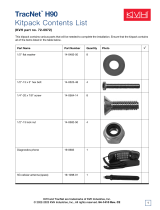
A complete satellite TV system, illustrated in Figure 1-1, includes
the TracVision 4 connected to an integrated receiver/decoder
(IRD) and a television set. A desktop or laptop computer is used
to configure the system for satellite selection and conduct
diagnostics. System specifications are provided in Appendix A.
1.1 Materials Provided With
TracVision 4 System
Table 1-1 lists the components and materials in the TracVision 4
shipping carton.
Component KVH Part No.
Antenna Unit 01-0234-01
Installation Kitpack 72-0099
Data Cable 32-0619-50
PC Cable 32-0628-06
Introduction
1-1
54-0150 Rev. E
Satellite Receiver 2
Satellite Receiver 1
Options Purchased Separately
TracVision 4 Antenna
Power
RF
TV 1
TV 2
RF
Data
11-16 Volts DC
3.5-4.5 Amps
Vessel
Power
PC Maintenance Port
Figure 1-1
TracVision 4 System Configuration
Table 1-1
TracVision 4 Packing List

Component KVH Part No.
Power Cable 32-0510-50
RF Cable 32-0417-50
IRD Ground Wire 32-0583-50
Switchplate 02-1023
TracVision 4 Technical Manual 54-0150
TracVision 4 User’s Guide 54-0150-01
1-2
TracVision 4 Installation and Technical Manual

2 Installation
TracVision 4 is designed for simple installation and setup. Just
follow these easy steps:
Step Refer to Section...
1. Choose the hardware locations 2.1
2. Mount the Antenna Unit 2.2
3. Set the skew angle (Europe only) 2.2.1
4. Wire system components 2.3
5. Program the IRD (Europe only) 2.4
6. Install selected satellite pair 2.5.1
7. Load any user-selected satellites 2.5.2
8. Check out system 2.6
Materials and Equipment Required for Installation
• Electric drill
•
3
⁄8" (10 mm) drill bit and 3" (80 mm) hole saw
• Socket wrenches
• Flat tip and Phillips screwdrivers
• RG-6 (75 ohms) cable for a second RF signal cable
(if necessary)
• Crimp tool (LRC #L3011B or equivalent)
• Light hammer; center punch; tape; scriber/pencil
• Terminal lug crimping tool; wire strippers
• A PC with terminal emulation software such as
PROCOMM, Windows Terminal, or Windows
95/98 Hyperterminal
2-1
Installation
54-0150 Rev. E
Plan the entire installation before
proceeding! Take into account
antenna unit placement, running
cable distances between units, and
accessibility to the equipment after
installation. Cable lengths are
detailed in Table 2-2.
KVH recommends the use of
RG-6 (75 ohms) cable for RF
wiring. Use of non-RG-6
(75 ohms) cables will result in
degraded performance.The KVH
warranty does not cover degraded
performance due to improper
wiring.
Table 2-1
Installation Process

Below-decks Cable Lengths
The major considerations in locating the below-decks equipment
are accessibility and cable lengths between units. Lengths of these
cables are as follows:
Cable (Function) Length
Data Cable (Switchplate to Antenna Unit) 50 ft (15 m)
RF Cable (Antenna to IRD) 50 ft (15 m)
Power Cable (Power to Antenna Unit) 50 ft (15 m)
IRD Ground Wire 50 ft (15 m)
2.1 Choosing the Best Location and
Getting the Best Reception
There are several factors to consider when choosing the
respective locations of the TracVision 4 antenna unit.
• The ideal antenna site has a clear view of the
horizon/satellite all around.
• Tracking errors will be reduced if the antenna
forward arrow is aligned as closely as possible
with the vessel’s centerline.
• Place the Antenna Unit as close to the intersection
of the vessel’s fore-and-aft centerline and midships.
• Keep the antenna out of line with nearby radars,
as their energy levels may overload the antenna’s
front-end circuits. If necessary, position the
Antenna Unit so it is at least four feet (1.3 meters)
above or below the level of the radar.
• Make sure that the mounting surface is rigid so
that it cannot flex when the vessel vibrates. If
necessary, add a strength member to the mounting
site to stiffen it.
2.2 Installing the Antenna Unit
Specifics of installation will vary with vessel design but the
following procedures are applicable in most situations and will
result in a secure and effective installation.
2-2
TracVision 4 Installation and Technical Manual
The radome exterior is treated
with a special finish selected for
compatibility with the dome material
and transparency to the satellite
signals. Application of additional
paints or finishes WILL degrade
performance, potentially beyond
acceptable limits.
The Antenna Unit should not be too
high off the water (a height above
the waterline no more than half the
vessel length).
Table 2-2
Lengths of Provided
Below-decks Cables

Table 2-3 lists the components provided in the Antenna Unit
Installation kitpack.
Part Qty.
1
⁄4-20 hex screws 4
1
⁄4 flat washers 8
1
⁄4-20 self-locking nuts 4
Plastic screw covers 6
Antenna base seal gasket 1
Tie-wraps 2
Core clamp 1
Tips for Successful Antenna Unit Placement and Mounting
• The mounting surface should be essentially flat,
free of vibration and flexing, and strong enough to
carry the complete assembly (30 lbs/13.6 kg).
• The antenna unit need not be located exactly on
the vessel’s fore-and-aft axis, but its centerline
reference MUST be parallel to it.
• Be sure to account for the radome height and the
base dimensions, illustrated in Figure 2-1.
Antenna Unit Mounting Procedure
1. Using the base dimensions presented in Figure 2-1
on the following page or the template provided in
Appendix B, lay out the four mounting bolt holes.
Check the layout of the baseplate to ensure that it
is parallel with the vessel’s fore/aft axis.
2-3
Installation
54-0150 Rev. E
Table 2-3
Antenna Unit Kitpack Contents
Always lift the antenna unit by the
gray baseplate structure, not the
radome. Also be careful not to
strike the exposed connectors
extending from the bottom of the
baseplate or allow them to carry
the weight of the antenna unit.

2. Drill four
3
⁄8" (10 mm) bolt holes. Mark a
3" (80 mm) diameter circle in the center of the
pattern and cut out to make a passage for the
cables to connect to the baseplate. Smooth the
edges of the hole to protect the cables.
3. Place the foam seal in position on the mounting
surface with the hole centered over the cable
access cutout and the paper backing on the
bottom. Do not remove the paper backing at this
time. Align the seal with the vessel’s fore-and-aft
line and the small end pointed forward as shown
in Figure 2-2. Scribe a line all around the seal.
2-4
TracVision 4 Installation and Technical Manual
Figure 2-2
Baseplate/Foam Seal Orientation
(Bottom View)
Bow
RF1
RF2
J14 (data)
J13 (power)
Foam Seal
Figure 2-1
Antenna Unit Dimensions
A template of the baseplate
mounting holes has been provided
in Appendix B.

4. Remove and save the three screws holding the
radome to the baseplate. Carefully lift the radome
straight up until clear of the antenna assembly and
set it aside in a safe place.
5. Position the baseplate assembly in place over the
mounting holes and cable access. Ensure that all
holes line up and that the connectors are centered
over the cable access. Make any necessary
adjustments before seating the foam seal in place
permanently.
6. Clean the surface where the foam seal will be
placed. Remove the paper backing from the foam
seal to expose the contact cement. Lay the foam
seal in place, adhesive side down, and press down
firmly to bring the adhesive into full contact along
the bottom. Ensure the narrow end points toward the
bow.
7. Bring the Data Cable, RF Cable(s), and Power
Cable up through the access hole and connect
them to the baseplate. Turn the connectors down
securely, but don’t use excessive force; finger-tight
is sufficient. Figure 2-3 illustrates the connector
assignments.
Do not use teflon gel on the cable fittings as it
reduces signal strength at higher frequencies.
8. Remove the foam shipping restraint from the
Antenna Unit.
9. Place the baseplate over the holes drilled in the
foundation, ensuring the forward arrow points
toward the bow. Rotate the azimuth mechanism
plate to expose each mounting hole. When rotating
the azimuth mechanism by hand, go slowly. Hitting the
stops with excessive force will damage the azimuth limit
switch.
10. Place a flat washer from the kitpack on a bolt and
insert the bolt into its hole from above as shown in
Figure 2-4.
11. Apply a flat washer and lock nut from underneath
as shown in Figure 2-4.
12. Tighten securely until the foam seal is compressed
as far as it will go and all four feet are bottomed
against the mounting surface.
2-5
Installation
54-0150 Rev. E
Figure 2-3
Baseplate Connector Assignments
Single IRD
Installation
Second IRD
Installation
The foam shipping restraint must
be removed before power is
applied. Save the foam for reuse
and be sure to install it whenever
the Antenna Unit is moved from
place to place. See Section 4.8,
“Preparation for Shipment,” for
instructions on preparing for
shipment.
Figure 2-4
Bolting the Antenna Unit to
the Deck (Side View)

2-6
TracVision 4 Installation and Technical Manual
13. For European systems, please refer to Section 2.2.1,
“Setting the Skew Angle.” North American systems
may proceed to step 14.
14. Replace the radome over the baseplate. Align the
radome screw holes with the nut holders, insert
the screws and tighten. Install a protective plastic
screw cap from the kitpack over each screw.
Several spare protective caps are provided.
2.2.1 Setting the Skew Angle (European
Systems Only)
The Antenna LNB skew angle must be adjusted to optimize
channel reception. Refer to your satellite service provider for the
proper skew angle for the selected satellite service and
geographical location.
Adjusting the LNB Skew Angle
1. Turn off the power to the Antenna Unit.
2. Remove the radome and set it aside.
3. Loosen the two wing screws securing the LNB
within the choke feed as illustrated in Figure 2-5.
4. Refer to the LNB skew angle labels on the end of
the LNB and on the LNB choke feed (pictured in
Figure 2-6) and adjust the LNB as necessary to
match as closely as possible the skew angle
provided by your service provider.
5. Retighten the wing screws.
2.3 Wiring the TracVision 4 System
A switchplate has been provided to serve as the hub of the
TracVision 4 wiring (with the exception of the RF cable, which
will be connected to the IRD). This switchplate includes an
ON/OFF switch and a DB9 maintenance port for easy access to
the Antenna Unit’s software and diagnostics.
Figure 2-5
Adjusting the European
LNB Skew Angle
Figure 2-6
Skew Angle Labels

2-7
54-0150 Rev. E
Follow these steps to begin the wiring process:
1. Select a location to mount the TracVision 4
switchplate. It should be flat and within reach of
the cables connected to the Antenna Unit.
2. Create a panel cutout in the mounting surface.
Figure 2-7 illustrates the mounting dimensions
and a template has been provided in Appendix C.
3. Run the Antenna power and data cables from the
Antenna Unit and out through the panel cutout.
4. Run a cable from ship’s power (11-16 Vdc) through
the panel cutout.
You are now ready to wire the TracVision 4 system to the
switchplate connectors and ship’s power.
Tips for Safe and Successful Wiring
• When attaching cables to the TracVision 4
switchplate connectors, make sure the insulation is
stripped back approximately
3
⁄16" (5 mm). Twist the
wires gently to help achieve a good connection. Do
not pinch insulation inside the connector.
• After attaching the power and data cables to the
appropriate terminal connector strips, tug gently
to ensure a firm connection.
Installation
A full-scale panel cutout template
has been provided in Appendix C.
Figure 2-7
Switchplate Panel Cutout
Dimensions
Figure 2-8
Correctly Securing Wires within
the Switchplate Connectors
/