Page is loading ...

User Guide
HDXP Plus Series
Matrix Switchers
Matrix Switchers
68-1200-01 Rev. B
10 13

Safety Instructions
Safety Instructions • English
WARNING: This symbol, , when used on the product, is intended to
alert the user of the presence of uninsulated dangerous voltage within the
product’s enclosure that may present a risk of electric shock.
ATTENTION: This symbol, , when used on the product, is intended
to alert the user of important operating and maintenance (servicing)
instructions in the literature provided with the equipment.
For information on safety guidelines, regulatory compliances, EMI/EMF
compatibility, accessibility, and related topics, see the Extron Safety and
Regulatory Compliance Guide, part number 68-290-01, on the Extron website,
www.extron.com.
Instructions de sécurité • Français
AVERTISSEMENT : Ce pictogramme, , lorsqu’il est utilisé sur le
produit, signale à l’utilisateur la présence à l’intérieur du boîtier du produit
d’une tension électrique dangereuse susceptible de provoquer un choc
électrique.
ATTENTION : Ce pictogramme, , lorsqu’il est utilisé sur le produit,
signale à l’utilisateur des instructions d’utilisation ou de maintenance
importantes qui se trouvent dans la documentation fournie avec le
matériel.
Pour en savoir plus sur les règles de sécurité, la conformité à la réglementation,
la compatibilité EMI/EMF, l’accessibilité, et autres sujets connexes, lisez les
informations de sécurité et de conformité Extron, réf. 68-290-01, sur le site
Extron, www.extron.fr.
Sicherheitsanweisungen • Deutsch
WARNUNG: Dieses Symbol auf dem Produkt soll den Benutzer
darauf aufmerksam machen, dass im Inneren des Gehäuses dieses
Produktes gefährliche Spannungen herrschen, die nicht isoliert sind
und die einen elektrischen Schlag verursachen können.
VORSICHT: Dieses Symbol auf dem Produkt soll dem Benutzer in der
im Lieferumfang enthaltenen Dokumentation besonders wichtige Hinweise
zur Bedienung und Wartung (Instandhaltung) geben.
Weitere Informationen über die Sicherheitsrichtlinien, Produkthandhabung,
EMI/EMF-Kompatibilität, Zugänglichkeit und verwandte Themen finden Sie in
den Extron-Richtlinien für Sicherheit und Handhabung (Artikelnummer
68-290-01) auf der Extron-Website, www.extron.de.
Instrucciones de seguridad • Español
ADVERTENCIA: Este símbolo, , cuando se utiliza en el producto,
avisa al usuario de la presencia de voltaje peligroso sin aislar dentro del
producto, lo que puede representar un riesgo de descarga eléctrica.
ATENCIÓN: Este símbolo, , cuando se utiliza en el producto, avisa
al usuario de la presencia de importantes instrucciones de uso y
mantenimiento recogidas en la documentación proporcionada con el
equipo.
Para obtener información sobre directrices de seguridad, cumplimiento
de normativas, compatibilidad electromagnética, accesibilidad y temas
relacionados, consulte la Guía de cumplimiento de normativas y seguridad de
Extron, referencia 68-290-01, en el sitio Web de Extron, www.extron.es.
Инструкция по технике безопасности • Русский
ПРЕДУПРЕЖДЕНИЕ: Данный символ, , если указан
на продукте, предупреждает пользователя о наличии
неизолированного опасного напряжения внутри корпуса
продукта, которое может привести к поражению
электрическим током.
ВНИМАНИЕ: Данный символ, , если указан на продукте,
предупреждает пользователя о наличии важных инструкций
по эксплуатации и обслуживанию в руководстве,
прилагаемом к данному оборудованию.
Для получения информации о правилах техники безопасности,
соблюдении нормативных требований, электромагнитной
совместимости (ЭМП/ЭДС), возможности доступа и других
вопросах см. руководство по безопасности и соблюдению
нормативных требований Extron на сайте Extron: www.extron.ru,
номер по каталогу - 68-290-01.
Chinese Simplified(简体中文)
警告: 产品上的这个标志意在警告用户该产品机壳内有暴露的危险 电压,
有触电危险。
注意: 产品上的这个标志意在提示用户设备随附的用户手册中有
重要的操作和维护(维修)说明。
关于我们产品的安全指南、遵循的规范、EMI/EMF 的兼容性、无障碍
使用的特性等相关内容,敬请访问 Extron 网站 www.extron.cn,参见 Extron
安全规范指南,产品编号 68-290-01。
Chinese Traditional( )
警告: 若產品上使用此符號,是為了提醒使用者,產品機殼內存在著
可能會導致觸電之風險的未絕緣危險電壓。
注意 若產品上使用此符號,是為了提醒使用者。
有關安全性指導方針、法規遵守、EMI/EMF 相容性、存取範圍和相關主題的詳
細資訊,請瀏覽 Extron 網站:www.extron.cn,然後參閱《Extron 安全性與法
規遵守手冊》,準則編號 68-290-01。
Japanese
警告: この記号 が製品上に表示されている場合は、筐体内に絶縁されて
いない高電圧が流れ、感電の危険があることを示しています。
注意: この記号 が製品上に表示されている場合は、本機の取扱説明書
に 記 載されている重 要 な操 作と保 守 ( 整 備 )の指 示についてユーザー の 注
意を喚起するものです。
安全上のご注意、法規厳守、EMI/EMF適合性、その他の関連項目に
つ い て は 、エ ク スト ロ ン の ウェ ブ サ イト www.extron.jp よ り 『 Extron Safety and
Regulatory Compliance Guide』 ( P/N 68-290-01) をご覧ください。
Korean
경고: 이 기호 가 제품에 사용될 경우, 제품의 인클로저 내에 있는
접지되지 않은 위험한 전류로 인해 사용자가 감전될 위험이 있음을
경고합니다.
주의: 이 기호 가 제품에 사용될 경우, 장비와 함께 제공된 책자에 나와
있는 주요 운영 및 유지보수(정비) 지침을 경고합니다.
안전 가이드라인, 규제 준수, EMI/EMF 호환성, 접근성, 그리고 관련 항목에
대한 자세한 내용은 Extron 웹 사이트(www.extron.co.kr)의 Extron 안전 및
규제 준수 안내서, 68-290-01 조항을 참조하십시오.

FCC Class A Notice
This equipment has been tested and found to comply with the limits for a Class A digital device,
pursuant to part15 of the FCC rules. The ClassA limits provide reasonable protection against harmful
interference when the equipment is operated in a commercial environment. This equipment generates,
uses, and can radiate radio frequency energy and, if not installed and used in accordance with the
instruction manual, may cause harmful interference to radio communications. Operation of this
equipment in a residential area is likely to cause interference; the user must correct the interference at
his own expense.
NOTE: For more information on safety guidelines, regulatory compliances, EMI/EMF compatibility,
accessibility, and related topics, see the “Extron Safety and Regulatory Compliance
Guide
” on the Extron website.
Copyright
© 2013 Extron Electronics. All rights reserved.
Trademarks
All trademarks mentioned in this guide are the properties of their respective owners.
The following registered trademarks
®
, registered service marks
(SM)
, and trademarks
(TM)
are the property of
RGBSystems, Inc. or Extron Electronics:
Registered Trademarks
(®)
AVTrac, Cable Cubby, CrossPoint, eBUS, EDID Manager, EDID Minder, Extron, Flat Field, GlobalViewer, Hideaway, Inline, IPIntercom, IPLink,
Key Minder, LockIt, MediaLink, PlenumVault, PoleVault, PowerCage, PURE3, Quantum, SoundField, SpeedMount, SpeedSwitch, System
Integrator, TeamWork, TouchLink, V-Lock, VersaTools, VN-Matrix, VoiceLift, WallVault, WindoWall, XTP and XTP Systems
Registered Service Mark
(SM)
: S3 Service Support Solutions
Trademarks
(
™
)
AAP, AFL (Accu-Rate Frame Lock), ADSP (Advanced Digital Sync Processing), AIS (Advanced Instruction Set), Auto-Image, CDRS (Class D
Ripple Suppression), DDSP (Digital Display Sync Processing), DMI (Dynamic Motion Interpolation), DriverConfigurator, DSPConfigurator, DSVP
(Digital Sync Validation Processing), FastBite, FOXBOX, IP Intercom HelpDesk, MAAP, MicroDigital, ProDSP, QS-FPC (QuickSwitch Front Panel
Controller), Scope-Trigger, SIS, Simple Instruction Set, Skew-Free, SpeedNav, Triple-Action Switching, XTRA, ZipCaddy, ZipClip

Conventions Used in this Guide
Notifications
The following notifications are used in this guide:
WARNING: A warning indicates a situation that has the potential to result in death or
severe injury.
ATTENTION: Attention indicates a situation that may damage or destroy the product or
associated equipment.
NOTE: A note draws attention to important information.
TIP: A tip provides a suggestion to make working with the application easier.
Software Commands
Commands are written in the fonts shown here:
^AR Merge Scene,,Op1 scene 1,1 ^B 51 ^W^C
[01] R 0004 00300 00400 00800 00600 [02] 35 [17] [03]
E X! *X1&* X2)* X2#* X2! CE}
NOTE: For commands and examples of computer or device responses mentioned
in this guide, the character “0” is used for the number zero and “O” is the capital
letter “o.”
Computer responses and directory paths that do not have variables are written in the font
shown here:
Reply from 208.132.180.48: bytes=32 times=2ms TTL=32
C:\Program Files\Extron
Variables are written in slanted form as shown here:
ping xxx.xxx.xxx.xxx —t
SOH R Data STX Command ETB ETX
Selectable items, such as menu names, menu options, buttons, tabs, and field names are
written in the font shown here:
From the File menu, select New.
Click the OK button.
Specifications Availability
Product specifications are available on the Extron website, www.extron.com.

Contents
Saving and Recalling Presets ........................ 29
Muting and Unmuting Outputs ...................... 33
Locking the Front Panel (Executive Mode)..... 35
Setting the Button Background
Illumination .................................................. 35
Selecting the RS-232 or RS-422 Protocol
and Baud Rate ............................................ 36
Resetting ...................................................... 37
Troubleshooting ................................................ 40
Configuration Worksheets................................. 41
Worksheet Example 1: System
Equipment ................................................... 41
Worksheet Example 2: Daily Configuration .... 42
Worksheet Example 3: Test Configuration ..... 43
Remote Configuration and Control ...........45
Serial Ports ....................................................... 45
Ethernet Port .................................................... 46
Ethernet Cable .............................................. 46
Default IP Addresses .................................... 46
Establishing an Ethernet Connection............. 46
Number of Connections ................................ 47
Verbose Mode .............................................. 47
Host-to-Switcher Instructions ........................... 47
Switcher-Initiated Messages ............................. 47
Switcher Error Responses ................................ 48
Using the Command and Response Table
for SIS Commands .......................................... 49
Symbol Definitions ........................................ 49
Command and Response Table for SIS
Commands ..................................................... 54
Introduction ...................................................1
About this Guide ................................................. 1
About the HDXP Plus Series Matrix Switchers .... 1
Features ............................................................. 2
Application Diagrams .......................................... 5
Installation ..................................................... 6
Rear Panels and Cabling .................................... 6
Connections ....................................................... 7
Video Connections ......................................... 7
External Sync Connections (HDXP 3232
only) .............................................................. 8
Reset Button .................................................. 9
Ethernet Connection ..................................... 10
RS-232 and RS-422 Remote
Connections ................................................ 11
Power ........................................................... 12
Operation ..................................................... 13
Front Panel Controls and Indicators .................. 13
Definitions ..................................................... 13
Input and Output Buttons ............................. 14
Configuration Port (HDXP 3232 Only)............ 15
Control Buttons ............................................ 15
I/O Buttons ................................................... 16
Operations........................................................ 17
Powering On ................................................ 17
Creating a Configuration ............................... 17
Previewing an Input ...................................... 23
Viewing the Configuration ............................. 24
I/O Grouping ................................................. 26
v
HDXP Plus Series Switchers • Contents

Matrix Software ...........................................67
Matrix Switchers Control Program .................... 67
Downloading the Matrix Software Control
Program
...................................................... 67
Software Operation Via Ethernet ................... 69
Special Characters
....................................... 69
Using the Software ....................................... 70
Setting up the Matrix window ....................... 73
Managing Ties
.............................................. 74
IP Setup ....................................................... 75
Updating the Firmware
................................. 81
Uploading HTML Files ................................... 83
Windows Buttons, Menus, and Trash Can .... 84
Windows Menus
........................................... 84
Using Emulation Mode .................................. 89
Using the Matrix Switcher Help System
........ 91
Creating Button Labels ..................................... 92
Button Icons
................................................. 92
Using the Button Label Generator
................. 92
Replacing Button Labels
............................... 94
Blank Button Labels
..................................... 95
HTML Configuration and Control .............. 96
Accessing the Web Pages ................................ 96
Special Characters ....................................... 97
System Status Page
......................................... 98
DSVP Page
.................................................. 98
System Settings Page
...................................... 99
IP Settings Fields
........................................ 100
Date/Time Settings Fields ........................... 101
Passwords Page......................................... 102
Email Settings Page .................................... 103
Firmware Upgrade Page
............................. 105
Using the File Management Page
................... 107
Uploading Files ........................................... 107
Adding a Directory
...................................... 108
Other File Management Activities
................ 108
Set and View Ties Page
.................................. 109
Creating a Tie
............................................. 109
Output Settings Page ................................. 110
Global Presets Page ................................... 111
Reference Information ............................. 112
Mounting the Switcher .................................... 112
Setting an IP Address ..................................... 113
What is an IP Address?............................... 113
Choosing IP Addresses .............................. 113
Subnet Mask .............................................. 114
Pinging for the IP Address .......................... 114
Connecting as a Telnet Client ...................... 115
Subnetting, a Primer ................................... 117
HDXP Plus Series Switchers • Contents vi

HDXP Plus Series Switchers • Introduction 1
Introduction
This section gives an overview of the Extron HDXP Plus Series Matrix Switchers,
describes significant features of the series, and provides application diagrams.
• About this Guide
• About the HDXP Plus Series Matrix Switchers
• Features
• Application Diagrams
About this Guide
This user guide contains installation, configuration, and operating information for the
HDXP matrix switchers, including the HDXP 1616, HDXP 3216, and HDXP 3232 models.
The terms “HDXP,” “switcher,” and “HDXP switcher” are used in this guide to refer to all
three HDXP models.
About the HDXP Plus Series Matrix Switchers
The Extron HDXP Plus Series are multi-rate digital matrix switchers that distribute any
serial digital interface (SDI) or high definition serial digital interface (HD-SDI) input to any
combination of SDI and HD-SDI outputs. The HDXP matrix switchers can route multiple
input and output configurations simultaneously. They can route all SMPTE and ITU
standard serial digital video signals up to 2.97 gigabits per second (Gbps), including
dual-link HD-SDI digital video signals and high resolution signals from computer-video
graphics cards equipped with HD-SDI outputs. Three matrix sizes are available:
• HDXP 1616 (16 inputs by 17 outputs)
• HDXP 3216 (32 inputs by 17 outputs)
• HDXP 3232 (32 inputs by 33 outputs)
The HDXP inputs can equalize incoming signals on up to 330 feet (100 meters) of
high-quality cable, such as the Extron RG-6 Super High Resolution (SHR) coaxial cable.
The outputs can reclock and drive all digital signals up to 330 feet (100 meters) on RG-6
cable.
The HDXP Plus series switchers conform to SMPTE and ITU-R BT specifications and
support data rates of 19 megabits per second (Mbps) through 1.485 Gbps.
The zero-skew design of the HDXP ensures that dual-link HD-SDI signals are switched
with no timing errors. The inputs adapt to the incoming signal rate, while the output is
reclocked to the rate of the signal routed to it. The output reclocking can be disabled on
a per-output basis (in bypass mode), or it can be set to a fixed rate. For each input, the
HDXP can report if a signal is available or missing; and for each output, it can report the
signal frequency.
Inputs and outputs can be grouped together to form up to four functional sub-switchers,
based on data rate, video format, location, and so on. This facilitates installation and front
panel control.

HDXP Plus Series Switchers • Introduction 2
The HDXP can operate in two switching modes, selectable via front panel buttons:
• Matrix switching mode (mode 1): Any input may be switched to any output.
• Preview selection mode (mode 2): Any single input may be selected and
previewed.
Each HDXP switcher has the rear panel Remote RS232/RS422 port, the front panel
Config RS-232 port, and the LAN port for remote control and configuration. The switcher
can be controlled via the front panel, the Extron Simple Instruction Set (SIS) commands,
the HDXP web pages, and the Extron Windows-based control software via the RS-232 or
RS-422 link, or an Ethernet connection.
The HDXP 1616 and 3216 models are housed in rack-mountable, 2U (3.5 inches) high,
full rack wide metal enclosures. The HDXP 3232 has a 3U (5.25") high, full rack wide
metal enclosure, also rack mountable. Each model has an internal 100 VAC to 240 VAC,
50-60 Hz, 80 watt power supply that provides worldwide power compatibility.
Features
• Inputs — 16 or 32 SDI and HD-SDI video inputs on female BNC connectors
• Outputs — 17 or 33 SDI and HD-SDI video outputs (including one preview output)
on female BNC connectors
• Serial digital data rates from 19 Mbps to 1.485 Gbps — The HDXP switchers
can switch signals conforming to all serial digital and high definition serial digital video
transmission standards. They support carriage of embedded audio, ancillary data,
and the ID information of the data stream.
• Input cable equalization — Each input signal is automatically equalized. Typically,
a 1.485 Gbps input signal is equalized for distances of 330 feet (100 meters) on high
quality cable such as Extron RG-6/SHR coaxial cable.
• SDI-SMPTE 259M and HD-SDI-SMTPE 292M compliance — Automatically
adapts to SMPTE and ITU digital video standards for HD-SDI and SDI. Complies with
SMPTE 259M, ITU-R BT.601, SMPTE 292M, ITU-R BT.1120, and SMPTE 372M
standards.
• Automatic rate selection — The HDXP automatically detects and locks onto the
incoming data signal. It accepts the following SMPTE data rates:
• SDI (SMPTE 259M and ITU-R BT .601) — 143 Mbps, 177 Mbps, 270 Mbps,
and 360 Mbps
• SDI (SMPTE 344M) — 540 Mbps
• HD-SDI (SMPTE 292M and ITU-R BT .1120) — 1.485 Gbps
• HD-SDI (Dual link) (No Preview function) — 2.97 Gbps (1.485 Gbps x 2,
using two inputs and outputs)
• Digital Sync Validation Processing (DSVP) — In critical environments or
unmanned, remote locations, it may be vital to know that sources are active and
switching. Extron DSVP verifies that input sources are active by scanning all inputs
and outputs for active sync signals. It then provides feedback regarding the available
input signal and the output signal rate. This information can be displayed via the
RS-232 and RS-422 interfaces, Ethernet, and the Windows-based control software.
• Video Genlock (HDXP 3232 only) — Allows for vertical interval switching, and
enables smooth, seamless transitions when switching between synchronous video
sources. Separate bi-level (SDI) and tri-level (HD-SDI) references are provided on two
additional BNC connectors.

HDXP Plus Series Switchers • Introduction 3
• Input-output (I/O) grouping — Allows the matrix to be virtually divided into smaller
sub-switchers, making installation and control easier. I/O grouping allows specific
outputs, such as those designated for a specific purpose, to be grouped together.
• Output reclocking — Each output has a reclocker, which detects the rate of the
digital input signal stream and re-times the output signal to match it. This enables the
signal to travel farther through the cable. All digital signals are reclocked unless this
feature is disabled via remote control (bypass mode).
The following options are available for the output reclockers:
• They can automatically reclock the output to the incoming signal rate if it is one of
the eight standard SDI and HD-SDI rates. This is the default setting.
• They can be set to a specific rate via SIS commands, the web pages, or the
Windows-based control software.
TIP: This option is recommended if the signal will always be input at the
same rate. Setting to one rate ensures that time will not be lost while the
reclockers detect and re-time to the signal rate.
• They can be bypassed for non-standard signal rates (bypass mode).
• Input signal preview — A separate output is provided for previewing any input
without tying up one of the matrix outputs.
• Channel to channel isolation — Provides a high level of isolation between channels
and very low electromagnetic emissions to minimize signal leakage.
• Buffered input and output — Each input and output is individually buffered to
provide maximum performance and eliminate nearly all crosstalk.
• Viewing input or output mode — Allows you to see which individual inputs and
outputs are actively connected.
• Global memory presets — You can store up to 32 configurations in memory
as global presets. Preset locations are assigned to the input buttons and (where
necessary) output buttons. Up to 16 or 32 presets (depending on the number of
inputs and outputs) can be selected from the front panel for either saving or retrieving.
When a preset is retrieved from memory, it becomes the current configuration.
• Rooms — Each switcher can be programmed to group multiple outputs to specific
“rooms,” allowing them to have their own presets. This can be done via SIS
commands or the Windows-based control software.
• Room Presets — 100 room presets, each consisting of up to 16 outputs in a single
room, enable room configurations to be set up and stored. When a room preset is
recalled, it becomes the current room configuration.
• Switching flexibility — Outputs are individually buffered and independently matrix
switched, enabling you to do the following:
• Tie any input to any or all outputs.
• Switch multiple inputs to multiple outputs simultaneously. This allows all displays
(outputs) to change from source to source at the same time.
• RS-232 and RS-422 connections — An RS-232/RS-422 control port on the rear
panel connects the HDXP switcher to a computer running a control system (such as
the IP Link Global Configurator), the Windows-based control software, and the SIS
command set.
In addition, the HDXP 3232 has a 2.5 mm TRS configuration port on the front panel,
which provides an RS-232 connection only.

HDXP Plus Series Switchers • Introduction 4
• Front panel security lockout (executive mode) — If a matrix switcher is installed
in an open area, where operation by unauthorized personnel may be a problem,
this security lockout feature can be implemented. When the front panel is locked, a
special button combination, SIS command, or selection from the Windows-based
control software screens is required to unlock the front panel controller before it can
be operated.
• Operational flexibility — Operations such as input and output selection and
setting of presets can be performed via the front panel, Ethernet, or the serial ports.
The RS-232 and RS-422 link allows remote control via a PC or control system. The
Ethernet link allows a remote connection with two levels of password protection.
• Front Panel Control — The QuickSwitch Front Panel Controller (QS-FPC)
provides a discrete button for each input and each output. An input or output can
be selected or switched by a single press of its front panel button. The front panel
buttons are large, positive touch, illuminated pushbuttons that can be labeled with
text or graphics.
• Windows-based control program — The Extron Windows-based control
software program provides a versatile range of operational options with its
graphical interface and drag-and-drop or point-and-click operation. This program
also has an emulation mode that lets you create a switcher configuration file
at the home office and then download it for use by the switcher on site. This
program can be accessed via either an RS-232 or RS-422, or an IP connection.
• Simple Instruction Set (SIS) — The Telnet, RS-232, and RS-422 remote control
protocol uses SIS commands for easy programming and operation.
• IP (Ethernet) control — Allows the switcher to be controlled through an
Ethernet local area network (LAN) or wide area network (WAN) using standard
IP internet protocols. The HDXP web pages, accessed via Ethernet, provide an
alternative method to control and configure the switchers.
• Remote control panels and keypads — The HDXP switchers are remote
controllable via the optional X-Y switching control MKP 2000 or MKP 3000
keypads, connected to the switcher via Ethernet or the RS232/RS422 port.
The remote control devices are easy to use and provide tactile buttons for quick
selection. Each MKP can be used to select a different input, output, or preset.
• Button labeling — Labels for the three-colored front panel buttons may be created
with any Brother P-Touch labeler or with the Extron label software, which is shipped
with every Extron matrix switcher. Each input and output can be labeled with a
name, alphanumeric characters, or a color bitmap for easy, intuitive input and output
selection.
• E-mail notification — The built-in SMTP client feature sends out e-mail notifications
to specified addresses when a monitored input loses its signal, or when the switcher
is powered on. Up to eight e-mail recipients are allowed.
• Rack mounting — The HDXP switchers, which have integrated front panel mounting
brackets, can be mounted in any conventional 19" wide rack.
• Power supply — The 100 VAC to 240 VAC internal power supply provides
worldwide power compatibility.
• Upgradable firmware — The firmware that controls all switcher operations can be
upgraded in the field via RS-232, RS-422, or Ethernet, without taking the switcher out
of service, opening the switcher enclosure, and replacing the firmware chip. Firmware
upgrades are available for download on the Extron website, www.extron.com and
they can be installed using the Windows-based control program, SIS commands, or
the web pages.

HDXP Plus Series Switchers • Introduction 5
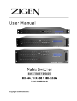
Application Diagrams
The following diagrams show examples of HDXP applications.
OUTPUTS
1
2
3
4
5
9
13
6
7
8
11
12
15
16
LAN
ACT
LINK
BI-LEVEL TRI-LEVEL
INPUTS
1
2
3
4
5
6
7
8
9
10
11
12
13
14
15
16
17
18
19
20
21
22
23
24
25
26
27
28
29
30
31
32
R
E
S
E
T
Remote User and
Administration Control
SDI/HD-SDI
Projectors
High Definition
Digital Media Servers
Digital Video
Tape Recorders
Extron
HDXP Plus Series
Multi-Rate Digital
Matrix Switcher
TCP/IP
SDI/HD-SDI
Displays/Monitors
I
N
P
U
T
S
1
2
3
4
5
6
7
8
9
10
11
12
13
14
15
16
O
U
T
P
U
T
S
1
2
3
4
5
6
7
8
9
10
11
12
13
14
15
16
17
2
3
4
21
6
7
8
25
10
11
12
29
14
15
16
17
18
19
20
21
22
23
24
25
26
27
28
29
30
31
32
LAN
ACT
LINK
BI-LEVEL
RESET
TRI-LEVEL
G
EN
-LO
C
K
PR
E
V
IEW
Remote User and
Administration Control
Plasma/LCD Displays
Projectors (SDI/HD-SDI)
High Definition
Digital Media Servers
Digital Video
Tape Recorders
Extron
HDXP Plus Series
Multi-Rate Digital
Matrix Switcher
TCP/IP
Figure 1. Application Diagrams for HDXP Plus

HDXP Plus Series Switchers • Installation 6
Installation
This section describes the rear panels of the HDXP switchers and provides instructions for
cabling and mounting. Topics include:
• Rear Panels and Cabling
• Connections
Rear Panels and Cabling
Most of the HDXP connectors are on the rear panel. Figures 2, 3, and 4 show the rear
panels of the HDXP 1616, 3216, and 3232 switchers.
INPUTS
1
2
3
4
5
6
7
8
9
10
11
12
13
14
15
16
OUTPUTS
1
2
3
4
5
6
7
8
9
10
11
12
13
14
15
16
LAN
ACT
LINK
Preview
RESET
1
5
6
7
3
2
8
Figure 2. HDXP 1616 Rear Panel
INPUTS
1
2
3
4
5
6
7
8
9
10
11
12
13
14
15
16
OUTPUTS
1
2
3
4
5
6
7
8
9
10
11
12
13
14
15
16
17
18
19
20
21
22
23
24
25
26
27
28
29
30
31
32
LAN
ACT
LINK
Preview
RESET
1
3
5
6
7
8
2
Figure 3. HDXP 3216 Rear Panel

HDXP Plus Series Switchers • Installation 7
FIG_HDXP 3232 Rear Panel
I
N
P
U
T
S
1
2
3
4
5
6
7
8
9
10
11
12
13
14
15
16
O
U
T
P
U
T
S
1
2
3
4
5
6
7
8
9
10
11
12
13
14
15
16
17
18
19
20
21
22
23
24
25
26
27
28
29
30
31
32
17
18
19
20
21
22
23
24
25
26
27
28
29
30
31
32
LAN
ACT
LINK
BI-LEVEL
RESET
TRI-LEVEL
GEN-LOCK
PREVIEW
1
5
6
7
3
8
4
2
Figure 4. HDXP 3232 Rear Panel
Connections
WARNING: Risk of Electric Shock. Remove power from the system before making
any connections.
ATTENTION: Use Electrostatic discharge precautions (be electrically grounded)
when making connections. Electrostatic discharge (ESD) can damage equipment,
although you may not feel, see, or hear it.
Video Connections
NOTE: The switchers do not alter the video signal in any way. The signal that is output
by the switcher is in the same format as the input signal.
a
Video inputs — Connect serial digital input sources to these female BNC
connectors.
b
Video outputs — Connect serial digital video output devices to these female BNC
connectors.
c
Preview output — Connect a digital display device to this female BNC connector to
enable you to preview a selected input when the switcher is in preview mode.

HDXP Plus Series Switchers • Installation 8
External Sync Connections (HDXP 3232 only)
d
External sync connectors for bi-level and tri-level — Connect an external
sync signal to this BNC connector to genlock the video signal in broadcast or other
sync-critical applications.
The HDXP switchers switch between inputs during the vertical interval period,
resulting in glitch-free video switching when the input devices are also using the same
sync timing. The HDXP can use an external signal to synchronize switching during the
vertical interval. Without this external sync locking feature, switching between inputs
could result in a brief rolling (sync loss) or a brief change in the picture size.
Figure 5 shows a basic external sync configuration. The Bi-level or Tri-level sync
connector receives the timing signal. A T connector attached to the cable allows the
signal to be passed on to another video device, if required. Terminate the T connector
if desired.
Extron
HDXP Plus 3232
Matrix Switcher
22
23
24
25
26
27
28
29
30
31
32
LAN
ACT
LINK
BI-LEVEL
RESET
TRI-LEVEL
GEN-LOCK
PREVIEW
POWER
12V
0.5A MAX
LR
1
4
3
2
1
6
5
PAL
NTSC
BLACKBURST
BLACKBURST/
COLORBAR
-10dBV
+4dBu
1 2 3
ON
1 KHZ AUDIO
BBG 6 A
BLACK BURST/COLOR BAR
/AUDIO GENERATOR
Terminate cable or
connect to another device
.
Connect to
HDXP Plus 3232.
T connector
OUT
Extron
BBG 6 A
Black Burst, Color Bars,
and Audio Generator
Figure 5. Simple HDXP 3232 External Sync Connection Example

HDXP Plus Series Switchers • Installation 9
Figure 6 shows a configuration in which the timing source passes through three video
cameras and a video scan converter before connecting to the switcher. This type of
camera can synchronize with the external timing source for video editing applications.
NOTE: I/O grouping is used to set the inputs associated with each reference
input. Input group 1 is associated with the tri-level signal and input group 2 is
associated with the bi-level signal.
Extr
on
BBG 6
A
Blac
kburst/Color Bars/
A
udio Generator
I
N
P
U
T
S
1
2
3
4
5
6
7
8
9
10
11
12
13
14
15
16
O
U
T
P
U
T
S
1
2
3
4
5
6
7
8
9
10
11
12
13
14
15
16
17
2
3
4
21
6
7
8
25
10
11
12
29
14
15
16
17
18
19
20
21
22
23
24
25
26
27
28
29
30
31
32
LAN
ACT
LINK
BI-LEVEL
RESET
TRI-LEVEL
G
EN-L
O
CK
PREVI
EW
50
/60
H
z
10
0-240
V
0
.3A
R
/
R
-
Y
R
/
R
-
Y
I
N
P
U
T
S
O
U
T
P
U
T
S
G
/
Y
2
R
G
B
/
R
-
Y
,
B
-
Y
,
Y
R
G
B
1
G
-
Y
B
/
B
-
Y
B
/
B
-
Y
H
/
H
V
H
/
H
V
V
V
V
I
D
E
O
S-VIDEO
D1
R
/
R
-
Y
G
/
Y
B
/B
-
Y
H
/
H
-
Y
R
S
-
2
3
2
/
4
2
2
G
E
N
L
O
C
K
V
I
N
O
U
T
SDI/HD-SDI
Video Camera
SDI/HD-SDI
Monitor
Extron
HDXP Plus 3232
Matrix Switcher
SDI/HD-SDI
Video Camera
SDI/HD-SDI
Video Camera
VGA Input
Extron
VSC 900D
Computer-to-Video
Scan Converter
(SDI only)
DISTRIB
U
TIO
N AM
PLIFIER
Figure 6. Multiple Device Example of an HDXP 3232 External Sync
If no external sync timing source is connected, switching occurs immediately.
Reset Button
e
Reset button — This recessed button initiates three levels of reset on the matrix
switcher. To initiate the different levels of reset, use a pointed object such as a stylus
or a small screwdriver to press and hold the Reset button while the switcher is
running or while you are powering it up (see Resetting on page 37 for details).
• Events (mode 3) reset — Hold the Reset button until the Reset LED blinks
once (approximately 3 seconds), then release it and press it again momentarily to
toggle events monitoring on and off.
• IP settings (mode 4) reset — Hold the Reset button until the Reset LED blinks
twice (approximately 6 seconds), then release it and press it again to reset the
switcher IP functions.
NOTE: IP settings reset does not replace any user-installed firmware.
Absolute (mode 5) reset — Hold the Reset button until the Reset LED blinks
three times (approximately 9 seconds), then release it and press it again to restore
the switcher to the default factory settings.
• Hard reset — Hold the Reset button while powering up the switcher to restore
the switcher to the default factory settings and factory installed firmware version.
NOTE: This type of reset does not clear the current configuration.

HDXP Plus Series Switchers • Installation 10
Ethernet Connection
f
LAN port — If desired, connect the HDXP switcher to a PC or to an Ethernet LAN
via this RJ-45 connector. Use a PC to control the networked switcher with SIS
commands (see the Remote Configuration and Control section, beginning on
page 45), the windows-based control program (see the Matrix Software section,
beginning on page 67), or the HTML pages (see the HTML Configuration and
Control section, beginning on page 96).
Ethernet connection indicators — The Link and Act LEDs indicate the
status of the Ethernet connection. The Link LED indicates that the switcher
is properly connected to an Ethernet LAN. This LED should light steadily.
The Act LED indicates transmission of data packets on the RJ-45 connector.
This LED should flicker as the switcher communicates.
Cabling and RJ-45 connector wiring
It is vital that you use the correct Ethernet cables, and that they be properly
terminated with the correct pinout. Ethernet links use Category (CAT) 5e or CAT 6,
unshielded twisted pair (UTP) or shielded twisted pair (STP) cables, terminated with
RJ-45 connectors. Ethernet cables are limited to a length of 328 feet (100 m).
NOTES:
• Do not use standard telephone cables. Telephone cables do not support
Ethernet or Fast Ethernet.
• Do not stretch or bend cables. Transmission errors can occur.
The Ethernet cable must be properly terminated for your application as either a
crossover or a straight-through cable.
• Crossover cable — Direct connection between the computer and the
HDXP switcher.
• Patch (straight) cable — Connection of the HDXP to an Ethernet LAN.
A cable that is wired as T568A at one end
and T568B at the other (Tx and Rx pairs
reversed) is a "crossover" cable.
A cable that is wir
ed the same at both ends
is called a "straight-through" cable because
no pin or pair assignments are swapped.
Both ends of the cable can be T568B
(as shown) or T568A (not shown).
RJ-45
Connector
Insert
Twisted
Pair Wires
12345678
Pins:
Crossover Cable Straight-through Cable
Pin
1
2
3
4
5
6
7
8
Wire Color
White-green
Green
White-orange
Blue
White-blue
Orange
White-brown
Brown
Wire Color
T568A
T568B
End 1 End 2 End 1 End 2
White-orange
Orange
White-green
Blue
White-blue
Green
White-brown
Brown
Pin
1
2
3
4
5
6
7
8
Wire Color
Blue
White-blue
White-brown
Brown
Wire Color
T568B
T568B
White-orangeWhite-orange
OrangeOrange
White-greenWhite-green
Blue
White-blue
GreenGreen
White-brown
Brown
Figure 7. RJ-45 Connector and Pinout Tables
ACT
LINK
LAN

HDXP Plus Series Switchers • Installation 11
The cable that you use depends on your network speed. The switcher supports
both 10 Mbps (10Base-T — Ethernet) and 100 Mbps (100Base-T — Fast Ethernet),
half-duplex and full-duplex, Ethernet connections.
• 10Base-T Ethernet requires CAT 3 UTP or STP cable at minimum.
• 100Base-T Fast Ethernet requires CAT 5e UTP or STP cable at minimum.
RS-232 and RS-422 Remote Connections
g
Remote RS232/RS422 connector — Connect a host device, such as a computer,
touch panel control, or RS-232 capable PDA to the switcher via this 9-pin D
connector for serial RS-232 or RS-422 control.
RS-232 FunctionPin Function
1
2
3
4
5
6
7
8
9
—
Tx
Rx
—
Gnd
—
—
—
—
Not used
Transmit data
Receive data
Not used
Signal ground
Not used
Not used
Not used
Not used
—
Tx–
Rx–
—
Gnd
—
Rx+
Tx+
—
Not used
Transmit data (–)
Receive data (–)
Not used
Signal ground
Not used
Receive data (+)
Transmit data (+)
Not used
RS-422
5
1
9
6
RS232 / RS422
REMOTE
Figure 8. Remote RS232/RS422 Connector
See the Remote Configuration and Control section beginning on page 45 for
definitions of the SIS commands (serial commands to control the switcher via this
connector) and the Matrix Software section beginning on page 67 for details on
how to install and use the control software.
NOTE: The switcher can support either an RS-232 or RS-422 serial
communication protocol, and operate at 9600, 19200, 38400, or 115200 baud
rates (see Selecting the RS-232 or RS-422 Protocol and Baud Rate on
page 36 to configure the RS232/RS422 port from the front panel).
If desired, connect an MKP 2000 or MKP 3000 remote control panel to the switcher
Remote RS232/RS422 connector (see the MKP 2000 Remote Control Panel User’s
Manual and the MKP 3000 User’s Manual for details).
RS-232 Config connector (front panel) — On the HDXP 3232 only, an additional
RS-232 port is located on the front panel. A host device can be connected to this
port for serial RS-232 control only. Protocol for the port is:
• 9600 baud
• 8 data bits
• 1 stop bit
• No parity
• No flow control

HDXP Plus Series Switchers • Installation 12
The optional 2.5 mm cable can be used to connect the HDXP to your computer.
Figure 9 shows the pin assignments for this cable.
I
6 feet
(1.8 m)
5
1
9
6
Sleeve
(Gnd)
Ring
Tip
6
9
9-pin D Connection TRS Plug
Pin 2 Computer Rx line Tip
Pin 3 Computer Tx line Ring
Pin 5 Computer signal ground Sleeve
Figure 9. 2.5 mm Connector Cable for the Configuration Port (HDXP 3232
Only)
See the Remote Configuration and Control section, beginning on page 45, and
the Matrix Software section beginning on page 67 for details about using SIS
commands and the control software to configure the HDXP.
Power
h
AC power connector — Plug a standard IEC power cord into this connector to
connect the switcher to a 100 VAC to 240 VAC, 50 or 60 Hz power source.

HDXP Plus Series Switchers • Operation 13
Operation
This section describes the HDXP front panel controls and the procedures for configuring
and operating the HDXP switchers. Topics include:
• Front Panel Controls and Indicators
• Operations
• Troubleshooting
• Configuration Worksheets
Front Panel Controls and Indicators
The front panel controls (see figures 10 and 11 on the next page) are grouped into two
sets. The input and output buttons are on the left side of the control panel. The control
buttons and video (I/O) selection buttons are on the right side of the panel.
These illuminated push buttons can be labeled with text and graphics. You can set
the buttons to have amber background illumination all the time, or you can turn off the
background illumination (see Setting the Button Background Illumination on page 35).
The buttons blink or light steadily (depending on the operation) when pressed.
You can re-label the input and output buttons by removing their numbered translucent
covers and inserting new labels behind the covers. An alternative set of labels is provided
and you can also create your own labels using the Extron Button Label Generator software
(also provided). See Creating Button Labels on page 92 for the procedure.
Definitions
The following terms, which apply to Extron matrix switchers, are used in this guide:
• Tie — An input-to-output connection.
• Set of ties — An input tied to two or more outputs. (An output can never be tied to
more than one input.)
• Configuration — One or more ties or one or more sets of ties.
• Current configuration — The configuration that is currently active in the switcher
(also called configuration 0).
• Global memory preset — A configuration that has been stored. Up to 32 global
memory presets can be stored in memory. Preset locations are assigned to the input
buttons and (where necessary) output buttons. All models have 32 presets available
from the front panel and under RS-232, RS-422, or Ethernet control.
When a preset is retrieved from memory, it becomes the current configuration.
• Room — A subset of outputs that are logically related to each other, as determined
by the operator. The switchers support up to 10 rooms, each of which can consist of
from 1 to 16 outputs.
• Room memory preset — A configuration consisting of outputs in a single room
that has been stored. When a room preset is retrieved from memory, it becomes the
current configuration for the outputs assigned to that room only (none of the other
outputs are affected).

HDXP Plus Series Switchers • Operation 14
FIG_Front panels
INPUTS
OUTPUTS
CONTROL I/O
1
2
3
4
5
6 7 8
9
10
11 12
13 14 15 16
1
2
3
4
5
6 7 8
9
10
11 12
13 14 15 16
17
18
19
20
21
22 23
24
25
26
27 28
29 30 31 32
HDXP PLUS SERIES
SDI AND HD-SDI MATRIX SWITCHER
1
ENTER
PRESET
VIEW
<
ESC
>
PREVIEW
MATRIX
2
4 5 6 7 8
9
Figure 10. HDXP 1616 and HDXP 3216 Front Panel
NOTE: On the HDXP 1616, which has only 16 input connectors, the input buttons in
the second row (buttons 17 through 32) can be used only for preset selection.
AUDIOVIDEO
I/OCONTROL
ENTERPRESET
VIEW ESC
I
N
P
U
T
S
1
2
3 4
5
6 7
8
9
10
11
12
14
15
16
13
17
18
19 20
21
22 23
24
25
26
27
28
30
31
32
29
17
18
19 20
21
22 23
24
25
26
27
28
30
31
32
29
1
2
3 4
5
6 7
8
9
10
11
12
14
15
16
13
O
U
T
P
U
T
S
SDI AND HD-SDI MATRIX SWITCHER
HDXP PLUS SERIES
CONFIG
1
2
3
4 5 6 7 8
9
Figure 11. HDXP 3232 Front Panel
Input and Output Buttons
a
Input buttons — The input buttons have two primary functions (
❏
) and three
secondary functions (
•
):
❏ Select an input.
❏ Identify the selected input.
• Input 1 only: With the Output 1 button, place the switcher in I/O grouping
mode (see I/O Grouping on page 26).
• Select a global preset (see Saving and Recalling Presets on page 29).
• Inputs 1 and 2 only: Activate or deactivate button background illumination (see
Setting the Button Background Illumination on page 35).
b
Output buttons — The output buttons have two primary functions (
❏
) and two
secondary functions (
•
):
❏ Select outputs.
❏ Identify the selected outputs.
• Output 1 only: With the Input 1 button, place the switcher in I/O grouping
mode (see I/O Grouping).
• Mute or unmute an output (see Muting and Unmuting Outputs on page 33).
/