Page is loading ...

1
MN-281
(141108)
ECR 7136
P/N 59510
Please read these instructions completely before proceeding with the installation.
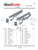
Figure 1

2
CAUTION: Failure to maintain correct minimum pressure
(or pressure proportional to the load), bottoming out, over-
extension, or rubbing against another component will void the
warranty. Normal ride height, regardless of load, must always
be maintained.
IMPORTANT: Your vehicle may be equipped with a rear brake
proportioning valve. Any type of load assist product could affect
brake performance. If equipped with a brake proportioning valve,
we recommend that you check with your dealer before installing
this type of product. If your vehicle does not have a rear brake
proportioning valve or is equipped with an anti-lock type brake
system, installation of a load assist product will have no effect
on brake system performance.
I. Getting Started
1. Determine the Ride Height.This is dened as the distance
betweenthebottomedgeofthefenderwelltothecenterpointof
thewheelwiththevehicleatthedesiredheight(withoutaload).
Measurementsshouldbetakenbeforebeginningtheinstallation.
The distance from the bottom edge of the fenderwell to the
centerpointofthewheelshouldberecorded.Allofourkitsare
designedtobeinstalledandoperateatnormalrideheight.
2. Measuretherideheightdistance.Enterthemeasurementbelow:
RideHeight:________inches
3. Aftermeasuringandrecordingtherideheight,jackuprearof
vehicleorraiseonhoist.Raiseaxleorlowerframeuntiltheleaf
springisatrideheight(unloadedcondition).
II.InstallingtheLowerBracket
1. Assemblethekit.Installtheairttingngertightplustwoturns.
Thisttingisprecoatedwiththreadsealant.Useanopenend
wrenchbeingcarefultotightenonthemetalhexnutonly.DO
NOT OVERTIGHTEN.
2. ThreadtheattachedairttingthroughthebottomoftheJ-bracket.
Positiontheelbowtowardsthefrontorrearofvehicledepending
onwhichdirectionwillalloweasieraccessfortheairline(Figures
1and2).Slidetheprovidednylonnutovertheairttingandonto
thethreadedpost.Tightenthenylonnuthandtighttosecure
thebracket(Figure4).
NOTE: The nylon nut must be threaded on the thread post
with the curved edge facing toward the sleeve (Figure 1).
3. Notethatthelowerbrackethastwomountingholes.Usingthe
outboardholeoneachside,LOOSELYattachthelowerbrackets
tothebottomofthesleevewiththeprovided1/2îatwasher
and1/2îboltasshowninFigure1.
4. NowinstallthelowerbracketasshowninFigure1.Thebracket
locatesovertheedgeoftheupperspringretainer(INSETA).
Figure 2
Figure 3
Inset A

3
Tightennutsto20ft.lbs.DO NOT OVERTIGHTEN.
CAUTION: Do not drill holes into the frame until any
hydraulic lines, gas lines and electrical wires have been
moved aside on both sides of the frame rail.
5. Toinstalltheupperbracket,lowertheaxleorraisetheframe
untiltheupperbracketisinlinewiththelowerandonthesame
angle as the leaf spring. The lower mounting surface of the
upperbracketmustbeparalleltothemountingsurfaceofthe
lowerbracketandthesleeveshouldbestraightwheninstalled
betweenthebrackets.Theupperbracketisdesignedsothatit
canbeìtiltedîfortheproperangle(Figure3).Thebottomofthe
upperbracketmustt tighttothebottomoftheframerail(Figure
4).Usingthebracketasatemplate,centerpunchanddrillthree
5/16îholes.Theholesmustbenolargerthan5/16î.Attachthe
upperbracketusingtheSelf-TappingFrameBoltsandtighten
securely(Figure1).DO NOT OVERTIGHTEN.
6. Selectalocationfortheinationvalvesintherearbumperarea
orrockerpanelange ensuringthateachvalvewillbeprotected
andaccessiblewithanairhose(Figure5).
7. Useastandardtubecutterorrazorbladetocuttheairlineinto
twoequallengths.Acleansquarecutwillensureagainstleaks.
Drilla5/16îholefortheinationvalveandmountasillustrated.
Theouterrubberwasherisusedasaweatherseal(Figure6).
8. Route airline alongframefrominationvalve location tothe
airtting(Figures1and5).Attachairlinetochassiswiththe
providedplasticstraps.
CAUTION: To prevent the air line from melting, keep it at
least 12 inches from the exhaust system.
9. Installtheairlineintothetting.Pushandslightlyturnthecut
endoftheairlineintothettingasfarasitwillgo(approximately
9
/16”).Adeniteìclickîcanbeheardand/orfeltwhentheairline
is seated. The air line is now installed.
10.Repeatsteps1-9fortheothersideofthevehicle.
11. VERY IMPORTANT: With the bottom still loose, inflate
the sleeve to approximately 10 p.s.i. By using the slotted
adjustment, center the sleeve so that it is in line with the
upper and lower brackets and that there is a symmetrical
cushion of air around the lower piston of the sleeve to
prevent side load wear. Sleeve diameter grows to 5.1î at
maximum inflation. Check to be sure there is sufficient
clearance around the sleeve when it is inflated. Tighten
the lower sleeve mounting bolt to 10 ft.lbs. DO NOT
OVERTIGHTEN.
12.Inateto 30 p.s.i.Check all ttings and valve core for leaks
with a soapy water solution.Recheck air pressure after 24
Figure 4
Figure 6
Figure 5

4
MaintenaceoftheSystem
1. Checkpressureweekly.
2. Alwaysmaintainatleast5p.s.i.airpressure.
3. Ifyoudevelopanairleakinthesystem,useasoapywatersolutiontocheckallairlineconnectionsandtheination
valvecorebeforeremovingsleeve.
OperationoftheSystem
1. Inateyourairspringsto60p.s.i.beforeaddingthepayload.Aftervehicleisloaded,adjustyourairpressureto
levelthevehicle.
2. IMPORTANT:Foryoursafetyandtopreventpossibledamagetoyourvehicle,donotexceedmaximumload
recommendedbythevehiclemanufacturer.Althoughyourairspringsareratedatmaximuminationpressureof
100p.s.i.,theairpressureactuallyneededisdependantontheloadandGrossVehicleWeightRating(GVWR),which
maybelessthan100p.s.i.Checkyourvehicleownerísmanualanddonotexceedmaximumloadslistedforyour
vehicle.
3. WheninatingyourAirLiftsleeves,addpressureinsmallquantities,checkthepressurefrequentlyduringination.
Thesleevesrequiremuchlessairvolumethanatireandthereforeinatemuchfaster.
4. Shoulditbecomenecessarytoraisethevehiclebytheframe,makesurethesystemisatminimumpressure(5
p.s.i.)toreducethetensiononsuspension/brakecomponents.Checktoseethattheairspringrollsbackdown
overthebottompistonafterthevehicleislowered(Figure9).Ifsleevefailstorollbackdownoverthepiston,add
airpressureuntilsleeveìpopsîbackoverpiston(donotexceed100p.s.i.).
NotCorrect:
misaligned or not
inated,onlyokduring
assembly
Correct:
nishedinstallation,
springinatedand
aligned
Figure 7
Failure to maintain correct minimum pressure (or pressure proportional to load),
bottoming out, over-extension, or rubbing against another component will void the
warranty.
Regardless of load, the air pressure must always be adjusted so that the normal
MAXIMUM AIR PRESSURE
MINIMUM AIR PRESSURE
5p.s.i. 100p.s.i.

5
“The Choice of the Professional Installer”
ForTechnicalAssistancecall1-800-248-0892
Thank you for purchasing Air Lift Products
MailingAddress: StreetAddress:
AIRLIFTCOMPANY AIRLIFTCOMPANY
P.O.Box80167 2727SnowRd.
Lansing,MI48908-0167 Lansing,MI48917
LocalPhone:(517)322-2144
Fax:(517)322-0240
Printed in the USA
/