Page is loading ...
Page is loading ...

Bedienungs- und Installationsanleitung
Installation- and Operation Instruction
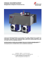
Messgaskühler / Sample Gas Coolers PKE-5xx
BX440010 08/2013 Art. Nr. 90 31 105
3
Contents page
1 Introduction ..................................................................................................................... 19
2 Important Advice ............................................................................................................. 19
2.1 General Indication of Risk ............................................................................................................... 20
3 Installation and Connection ............................................................................................ 22
3.1 Mounting .......................................................................................................................................... 22
3.2 Electrical Connection ....................................................................................................................... 23
4 Operation and Maintenance ............................................................................................ 24
4.1 Operation ......................................................................................................................................... 24
4.2 Operation of Menu Functions .......................................................................................................... 24
4.2.1 Overview of the Menu Items ........................................................................................................ 25
4.2.2 Detailed Description of the operational Principle ......................................................................... 26
4.3 Description of the Menu Functions .................................................................................................. 26
4.3.1 Main Menu ................................................................................................................................... 26
4.3.2 Submenu Peltier cooler (Display: P5__)...................................................................................... 27
4.4 Maintenance .................................................................................................................................... 27
5 Repair and Disposal ........................................................................................................ 28
5.1 Repair .............................................................................................................................................. 28
5.2 Disposal ........................................................................................................................................... 28
6 Appendices ...................................................................................................................... 29
6.1 Safety Instructions ........................................................................................................................... 29
6.2 Troubleshooting ............................................................................................................................... 30
6.3 Replacement of Micro-Fuse of the Cooler ....................................................................................... 31
6.3.1 115 V and 230 V .......................................................................................................................... 31
6.3.2 24 V DC ....................................................................................................................................... 31
6.4 Cleaning of the heat exchanger ....................................................................................................... 31
6.5 Replacing the Fuse of the peristaltic Pump ..................................................................................... 32
6.6 Replacement of the peristaltic pump’s hose (just in case pump is fitted)........................................ 32
6.7 Spare parts ...................................................................................................................................... 32
6.8 Attached documents ........................................................................................................................ 32
Page is loading ...
Page is loading ...
Page is loading ...
Page is loading ...
Page is loading ...
Page is loading ...
Page is loading ...
Page is loading ...
Page is loading ...
Page is loading ...
Page is loading ...
Page is loading ...
Page is loading ...
Page is loading ...
Page is loading ...

Bedienungs- und Installationsanleitung
Installation- and Operation Instruction
Messgaskühler / Sample Gas Coolers PKE-5xx
BX440010 08/2013 Art. Nr. 90 31 105
19
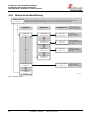
1 Introduction
The sample gas coolers of model range PKE 5xx are designed for applications in gas analysis systems. It is a
very important item in a sample conditioning system. Hence it is essential to read carefully the enclosed data
sheet and check that all application parameters are completely matched by the gas cooler.
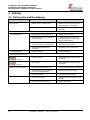
The model range of PKE 5xx consists of the types listed below. The exact type follows from the type plate on
the device and the electronics, respectively (see also menu description in chapter 4.2)
Basic type
ambient temperature
number of heat exchangers
PKE 511
+5…40°C
1
PKE 521
+5…50°C
1
PKE 512
+5…40°C
2
PKE 522
+5…50°C
2
Table 1: Specifications of PKE 5xx
2 Important Advice
Please check prior to installation of the device that the technical data matches the application parameters.
Check that the delivery is complete as well.
Operation of the device is only valid if
- the product is used under the conditions described in the installation- and operation instruction, the intended
application according to the type plate and the intended use. In case of unauthorized modifications done by
the user Bühler Technologies GmbH can not be held responsible for any damage,
- the performance limits given in the datasheets and in the installation- and operation instruction are obeyed,
- monitoring devices and safety devices are installed properly,
- service and repair is carried out by Bühler Technologies GmbH, unless described in this manual,
- only original spare parts are used.
This manual is part of the equipment. The manufacturer keeps the right to modify specifications without
advanced notice. Keep this manual for later use.
Signal words for warnings:
NOTE
Signal word for important information to the product
CAUTION
Signal word for a hazardous situation with low risk, resulting in damage to the device or the
property or minor or medium injuries if not avoided.
WARNING
Signal word for a hazardous situation with medium risk, possibly resulting in severe injuries
or death if not avoided.
DANGER
Signal word for an imminent danger with high risk, resulting in severe injuries or death if
not avoided

Bedienungs- und Installationsanleitung
Installation- and Operation Instruction
Messgaskühler / Sample Gas Coolers PKE-5xx
20
BX440010 08/2013 Art. Nr. 90 31 105
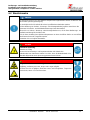
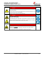
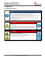
The following warning signs and signal words are used in this manual:
hazardous situation
disconnect from mains supply
hazardous voltage
wear face protector
electrical shock
wear respirator
toxic gases
wear gloves
corrosive Substances
Follow note
2.1 General Indication of Risk
Installation of the device shall be performed by trained staff only, familiar with the safety requirements and
risks.
Check all relevant safety regulations and technical indications for the specific installation place. Prevent failures
and protect persons against injuries and the device against damage.
The person responsible for the system must secure that:
- safety and operation instructions are accessible and followed,
- local safety regulations and standards are obeyed,
- performance data and installation specifications are regarded,
- safety devices are installed and recommended maintenance is performed,
- national regulations for disposal of electrical equipment are obeyed.
Maintenance and repair
- Repairs on the device must be carried out by Bühler authorized persons only.
- Only perform modifications, maintenance or mounting described in this manual.
- Only use original spare parts.
During maintenance regard all safety regulations and internal operation instructions.

Bedienungs- und Installationsanleitung
Installation- and Operation Instruction
Messgaskühler / Sample Gas Coolers PKE-5xx
BX440010 08/2013 Art. Nr. 90 31 105
21
DANGER
Electrical voltage
Electrocution hazard.
Disconnect the device from power supply. Make sure that the equipment cannot
be reconnected to mains unintentionally.
The device must be opened by trained staff only.
DANGER
Toxic and corrosive gases
Sample gas can be hazardous.
Take care that the gas is exhausted in a place where no persons are in danger.
Protect yourself during maintenance against toxic / corrosive gases. Use gloves,
respirator and face protector under certain circumstances.
DANGER
Explosion hazard if used in hazardous areas
The device is not suitable for operation in hazardous areas with potentially
explosive atmospheres.
Do not expose the device to combustible or explosive gas mixtures.

Bedienungs- und Installationsanleitung
Installation- and Operation Instruction
Messgaskühler / Sample Gas Coolers PKE-5xx
22
BX440010 08/2013 Art. Nr. 90 31 105
3 Installation and Connection
The PKE 5xx coolers are designed for indoors applications. If the device is installed outside provide sufficient
weather protection.
The PKE 5xx sample cooler is to be attached to vertical panels. Provide enough space below the device to
drain off condensate. Above leave some space for providing gas flow.
The allowed ambient temperature shall not exceed the values according to Table 1 on page 19. Free air
circulation must be provided. Leave enough space to any obstacle to the lateral ventilation grilles. Particularly
with regard to the air outlet (on the right) keep a gap of at least 10 cm (4 inches). If the device is mounted
inside closed covers, e.g. cabinets for gas analysis systems, provide adequate air circulation. If convection
alone is not sufficient, rinse the cabinet with air or install additional fans to lower the inner temperature.
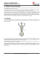
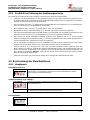
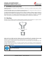
3.1 Mounting
With glass heat exchangers, make sure that the gasket is inserted in correct orientation. The gasket consists
of a silicon ring and a PTFE shield. The PTFE shield must point to the glass thread.
PTFE
Glass
A000268
Make sure that all sample gas lines leading to the cooler are installed with a downward slope. In some
applications with very high condensate content separators upstream the cooler could become necessary. Best
suited are our fluid separators with automatic condensate drain 11 LD, especially AK20 or type 165.
The gas entrance is marked with red. Connect the hoses to the heat exchangers made of DURAN glass with
care to avoid breaking the glass.
To drain condensate glass vessels or automatic condensate drains are provided for external mounting below
the device. If the sample gas pump is located upstream of the cooler, the condensate can be drained off by
automatic condensate drains.
NOTE
Heat exchangers MTS and MTV (cooler with two heat exchangers) cannot be used with
automatic condensate drains.

Bedienungs- und Installationsanleitung
Installation- and Operation Instruction
Messgaskühler / Sample Gas Coolers PKE-5xx
BX440010 08/2013 Art. Nr. 90 31 105
23
If the sample gas pump is installed downstream the cooler, we recommend using glass condensate vessels or
peristaltic pumps.
Mounting the condensate drains: depending on the used material the condensate drain may be connected to
the heat exchanger directly by stainless steel pipes or hoses. The condensate drains can be attached directly
to such coolers with stainless steel heat exchangers. In case of glass heat exchangers the condensate drains
must be connected with flexible hoses and fixed with by brackets separately. The condensate lines must be
installed with considerable slope and should not have less than 8 mm (0.3 inch) inner diameter.
If peristaltic pumps are used, they may be installed in some distance from the cooler.
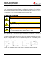
3.2 Electrical Connection
WARNING
The device must be installed by trained staff only.
CAUTION
Wrong mains voltage may damage the device.
Regard the correct mains voltage as given on the type plate.
WARNING
Damage to the device in case of insulation testing
Do not proceed insulation tests with high voltage to the device as a whole.
The device is equipped with extensive EMC protection. If insulation tests are carried out the electronic filter
devices will be damaged. All necessary tests have been carried out for all concerned groups of components at
the factory (test voltage 1 kV or 1.5 kV respectively, depending on the device).
The PKE5xx is equipped with two connectors on top of the unit. One connector is for the power supply and the
other one for the alarm output. They cannot be interchanged and must be wired according to the following
diagram (numbering can be found on the connectors). Make sure they are correctly refitted after wiring.
If the PKE 5xx is equipped with peristaltic pumps, they must be connected to a separate power supply.

Bedienungs- und Installationsanleitung
Installation- and Operation Instruction
Messgaskühler / Sample Gas Coolers PKE-5xx
24
BX440010 08/2013 Art. Nr. 90 31 105
4 Operation and Maintenance
4.1 Operation
After turning on the power supply the display shows the actual temperature of the cooling block. The display
blinks until the (set) temperature range with respect to the preset output dew point is reached. The status
contact is switched to “Alarm”.
If the temperature range is reached, the actual temperature is shown constantly and status contact switches
back.
If the display starts blinking during operation or an error message is displayed see chapter 6.1
“Troubleshooting”.
For performance limits see datasheet.
4.2 Operation of Menu Functions
Overview of the operational principal:
Use this short description if you have experience with Peltier coolers.
You will find detailed description in chapter 4.2.2 and chapter 4.1.
Keys:
Operation is carried out by only the keys with the following functions:
Key
Function
j
Switch from measurement display to main menu
Selection of the display menu item
Accepting the changed value or selection
t
Switch to the upper menu item
Increase of the value of switching the selection
Temporary display of the alternative measurement display (if option is installed)
b
Switch to lower menu item
Decrease of the value of switching the selection
Temporary display of the alternative measurement display (if option is installed)

Bedienungs- und Installationsanleitung
Installation- and Operation Instruction
Messgaskühler / Sample Gas Coolers PKE-5xx
BX440010 08/2013 Art. Nr. 90 31 105
25
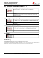
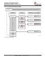
4.2.1 Overview of the Menu Items
Display of current temperature and operating state
Peltier Gas Cooler
Display: P5__
2°C...20°C
Display: xxxx
Global Settings
Display: toP
+1°C…+7C
Display: xxx
Exit Main Menu
Display: E
t b
Exit Submenu
Display: E
j
Main Menu
Set Temperature
Display: tEMP
Submenu
upper alarm threshold
Display: A Hi
Setting Range
Celsius/ Fahrenheit
Display: C [F]
j
j
t b
t b
t b
j
j
j
j
Current Temperature
Display: xxxx
Displayed is the block temperature with a resolution of 0.5°C. By pressing the Enter button brings the display to
the Main Menu. The unit of temperature is adjustable in the menu Global settings (Celsius or Fahrenheit).
Adjust the set point:
2°C...20°C
Set the upper alarm
Threshold above setpoint:
tEMP +1°C...+7°C
Set unit to Celsius or
Fahrenheit.
-1°C…-3C
Display: xxx
lower alarm threshold
Display: A Lo
j
t b
Set the lower alarm
Threshold below setpoint:
tEMP -1°C...-3°C
t b adjust value
j store value
wait 4s: no storage
VE 00 0001
Fig. 1: Overview of the menu

Bedienungs- und Installationsanleitung
Installation- and Operation Instruction
Messgaskühler / Sample Gas Coolers PKE-5xx
26
BX440010 08/2013 Art. Nr. 90 31 105
4.2.2 Detailed Description of the operational Principle
This detailed description leads you through the menu for the cooler step by step.
Connect the cooler to the power supply and wait until the power-up sequence has finished. First the
version of the implemented software is displayed for a short time. Then the device switches to the
measurement display.
Pressing the j key switches from display-mode to main menu. (It is guaranteed that the control
continues during setting-mode.)
You can navigate through the main menu using the t b keys according to Fig. 1.
To accept the menu item press j and the related submenu is activated.
Now the parameters may be set. To change the parameters scroll the submenu using the keys t b
and confirm the selected menu item with
The values can be changes within their limits using the keys t b. Pressing the enter key (j) stores
the set value. Afterwards the device returns to the submenu automatically.
Wait for a few seconds without pressing any key to return to the submenu without saving the values.
The same procedure holds for the sub- and main menu. If you forget to quit the menu, the system
returns automatically to display mode. In this case the preset values are kept instead of being reset.
Note: As soon as the values are saved by pressing the enter key, they are accepted for regulation.
Quit the main menu or the submenu by selecting the menu item E (Exit)
4.3 Description of the Menu Functions
4.3.1 Main Menu
Peltier cooler (PKE 5xx)
Peltier cooler:
This item allows all relevant settings for the Peltier cooler. In the corresponding
submenu nominal temperature and alarm limits may be selected.
Global settings (toP settings)
Top settings
Selection of the global temperature unit, either degree Celsius (C) or degree
Fahrenheit (F)
Note:
This menu item has no sub-item. The temperature unit is directly selected.
Exit main menu
Exit
Selecting this item returns to the display mode.

Bedienungs- und Installationsanleitung
Installation- and Operation Instruction
Messgaskühler / Sample Gas Coolers PKE-5xx
BX440010 08/2013 Art. Nr. 90 31 105
27
4.3.2 Submenu Peltier cooler (Display: P5__)
Peltier cooler Nominal temperature
Temperature
This item allows setting of the nominal temperature for the cooler. The value can
be set within a range from 2°C (35.6°F) to 20°C (68°F).
Note:
Default value at delivery is 5°C (41°F) (unless otherwise agreed).
Peltier cooler upper alarm threshold (Alarm high)
Alarm high
This item allows setting of the upper alarm threshold for the optical alarm as well
as for the alarm relay. The upper alarm threshold may be set in the range from
+1°C (+1.8°F) to +7°C (+13°F) above the nominal temperature.
Note:
Default value at delivery is +3°C (+5°F) (unless otherwise agreed).
Peltier cooler lower alarm threshold (Alarm low)
Alarm low
This item allows setting of the lower alarm threshold for the optical alarm as well
as for the alarm relay. The lower alarm threshold may be set in the range from -
1°C (-1.8°F) to -3°C (-5°F) below the nominal temperature.
Note:
Default value at delivery is -3°C (-5°F) (unless otherwise agreed).
Exit submenu
Exit
Selecting this item returns to the main menu.
4.4 Maintenance
Basic versions of the cooler run maintenance free.
If the PKE 5xx is equipped with a peristaltic pump, the hoses have to be checked in regular intervals depending
on the gas. Displacement of the hoses is described in chapter 6.4.

Bedienungs- und Installationsanleitung
Installation- and Operation Instruction
Messgaskühler / Sample Gas Coolers PKE-5xx
28
BX440010 08/2013 Art. Nr. 90 31 105
5 Repair and Disposal
5.1 Repair
If the device shows irregularities see chapter 6 for troubleshooting.
If you need help or more information
call +49(0)2102-498955 or your local agent.
If the device doesn’t work correctly after elimination of failures and turning power on, the device must be
checked by the manufacturer. Please ship the device with suitable packing to
Bühler Technologies GmbH
- Service -
Harkortstraße 29
40880 Ratingen
Germany
In Addition, attach the filled in and signed Declaration of Decontamination status to the packing. Otherwise,
your repair order cannot be processed! The form can be requested by e-mail to service@buehler-
technologies.com.
5.2 Disposal
Regard the local regulations for disposal of electric and electronic equipment.

Bedienungs- und Installationsanleitung
Installation- and Operation Instruction
Messgaskühler / Sample Gas Coolers PKE-5xx
BX440010 08/2013 Art. Nr. 90 31 105
29
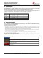
6 Appendices
6.1 Safety Instructions
NOTE
Trained staff only shall install the device. Check for correct supply voltage.
The cooler must not be operated out of the range of its specifications.
Regard the corresponding safety and operation regulations during maintenance or servicing.
Only perform modifications, servicing or mounting described in this manual.
Any manipulation on the gas cooler which is not described in this manual should only be
executed by Bühler authorised staff.
Only use original spare parts.
DANGER
Hazardous voltage
Electrocution hazard
Before any manipulation on the device, disconnect the electrical equipment from
the main power supply. Make sure that the electrical equipment cannot be
reconnected during repair or maintenance. The wiring must be done by trained
staff only.
DANGER
Toxic / corrosive gases and liquids
Poisoning, chemical burn of skin, eyes and lungs possible
Protect yourself against toxic / corrosive gases and liquids. If necessary wear
protection gloves, respirator and face protector.

Bedienungs- und Installationsanleitung
Installation- and Operation Instruction
Messgaskühler / Sample Gas Coolers PKE-5xx
30
BX440010 08/2013 Art. Nr. 90 31 105
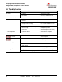
6.2 Troubleshooting
Problem / Failure
Possible cause
Solution
No display
- no power
- check power supply
- fuse blown
- Check fuse and change it if
necessary
Status-LED blinks with
- High Temperature
- operational temperature not yet
reached
- wait for 20 minutes maximum
- cooling capacity to low, even
though cooler is running
- make sure that air can circulate
free and that ventilation louvres
are not obstructed
- gas flow / dew point / gas tempe-
rature to high
- check application parameters,
install pre-separator
- fan broken
- check fan, replace if necessary
- Low temperature
- controller defect
- send cooler for inspection
Display of an error
Error 01
- broken wire
- Temperature sensor defect: send
cooler for repair
Error 02
- short circuit
- Temperature sensor defect: send
cooler for repair
Condensate in gas outlet
- condensate vessel full
- drain vessel
- valve in automatic condensate
drain is stuck
- flush both directions
- cooler overloaded
- check limiting parameters
Reduced gas flow
- clogged gas path
- check / flush heat exchanger
- condensate outlet clogged by ice
- send cooler for inspection

Bedienungs- und Installationsanleitung
Installation- and Operation Instruction
Messgaskühler / Sample Gas Coolers PKE-5xx
BX440010 08/2013 Art. Nr. 90 31 105
31
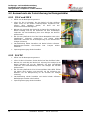
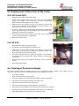
6.3 Replacement of Micro-Fuse of the Cooler
6.3.1 115 V and 230 V
Disconnect the cooler from power supply.
Loosen the 8 screws fixing the cover to the case. If peristaltic
pumps are installed to the cooler they must be disassembled
because they are fixed with the cover-screws.
Remove the cover carefully. Caution: The display is fixed to the
cover and is connected to the electronics inside the device. The
plug can be put off to lay the cover down.
The fuse is placed on the small supply circuit board, covered by a
plastic cap. Replace the fuse and refit the cap. Regard the supply
voltage for choosing the correct fuse.
Reconnect the plug of the display and fix the cover. Fasten the
screws or install the pumps, respectively.
Reconnect power supply.
6.3.2 24 V DC
Disconnect the cooler from power supply.
Loosen the 8 screws fixing the cover to the case.
Remove the cover carefully. Caution: The display is fixed to the
cover and is connected to the electronics inside the device. The
plug can be put off to lay the cover down.
The fuse is placed in the fuse holder (see picture). Turn to open it
and replace the fuse. Regard the supply voltage for choosing the
correct fuse.
Reconnect the plug of the display and fix the cover. Fasten the
screws.
Reconnect power supply.
6.4 Cleaning of the heat exchanger
The heat exchanger must be replaced only in case of damage or when clogged. In the latter case we
recommend to check if the use of a filter will avoid such clogging in the future.
Turn off gas supply.
Disconnect the cooler from the mains.
Loosen gas fittings and condensate drain fitting. Collect condensate.
Pull out the heat exchanger upwards out of the cooler.
Clean the cooling nest (hole in cooling block).
Clean the heat exchanger until all impurities are disposed.
Grease the heat exchanger on the cooling surfaces with silicone grease.
Introduce the heat exchanger with turning movement into cooling nest.
Re-establish fittings for gas tubes and condensate drain.

Bedienungs- und Installationsanleitung
Installation- and Operation Instruction
Messgaskühler / Sample Gas Coolers PKE-5xx
32
BX440010 08/2013 Art. Nr. 90 31 105
6.5 Replacing the Fuse of the peristaltic Pump
Disconnect the pump from the mains.
Remove the insulation cover from the fuse holder at the pump’s mounting bracket. For this, push the
cover using a screw driver and quarter-turn it to the left.
Replace the fuse and refit the insulation cover by quarter-turning it to the right.
Reconnect the cooler to the mains.
6.6 Replacement of the peristaltic pump’s hose (just in case pump
is fitted)
Turn off gas supply.
Switch the device off and disconnect power supply.
Disconnect input and output hoses (Take care of the safety instructions!)
Loosen but don’t remove the centre knurled thumb screw. Push screw downwards.
Remove cover
Push terminals side wards.
Replace hose and step backwards the above steps for mounting.
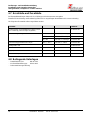
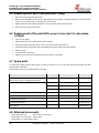
6.7 Spare parts
To order spare parts please indicate type of cooler and serial no. For accessories and enhancement see data
sheets and/or catalogue.
The following parts are recommended for stocking:
Spare part
Part no.
Replacement hose for peristaltic pump 0.3 l/h
(only if your cooler is equipped with pump)
91 240 30 027
Fuse cooler
230 V
5x20 mm, 1.25 A slow
91 100 00 058
115 V
5x20 mm, 2.5 A slow
91 100 00 013
24 V DC
5x20 mm, 6.3 A slow
91 100 00 063
Fuse peristaltic pump
230 V / 115 V
5x20 mm, 1 A fast-acting
91 100 00 061
Display ABT 400
91 000 10 124
Controller board MCP1
91 000 10 125
Controller board PKE
91 000 10 126
Mains board
91 000 10 127
6.8 Attached documents
- Data sheet PKE 5xx: DE 44 0012, DA 44 0012
- Declarations of conformity: KX 44 0002
- Declaration of Contamination status
Page is loading ...
Page is loading ...
Page is loading ...
Page is loading ...

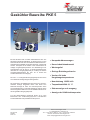
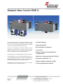
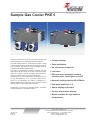
Sample Gas Cooler PKE 5
The PKE Models feature a semiconductor Peltier cooling
system with an aluminum cooling block. Fitted into the block
are one or two removable high efficient heat exchanger
made of stainless steel, DURAN-glass or PVDF.
The dew point of 5 °C is regulated by an electronic controller.
The temperature (in °C or °F) of the cooling block is shown on
a programmable LED-display. The status is indicated by a
flashing display which shows too high or low temperature
and operates together with a relay in fail-safe mode.
Condensate is removed by peristaltic pumps, automatic
condensate drains or condensate vessels.
The PKE 5 is designed for moderate ambient and gas
temperatures (150 l/h @ 70°C) and an inlet dew point of
about 40 °C (appox. 5 Vol%). For higher ambient tempera-
tures up to a maximum of 50 °C order the PKE 52x.
§
§
§
§
§
§
§
§
§
Compact design
Easy installation
No maintenance required
Low noise
Model available for high ambient
temperatures
Nominal cooling capacity 90/100 kJ/h
Dew point stability 0.1 °C
Status display and status output
Cooling temperature display
DE 44 0012
Page 1/4
02/2014
Bühler Technologies GmbH
D - 40880 Ratingen, Harkortstr. 29
Tel.: + 49 (0) 2102 / 4989-0 Fax: + 49 (0) 2102 / 4989-20
Internet: www.buehler-technologies.com
e-mail: [email protected]

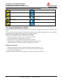
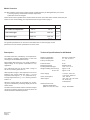
Model Overview
The PKE 5 Peltier cooler family includes several types which may be categorised by two criteria:
1) Cooling capacity and maximum ambient temperature
2) Number of heat exchangers
These criteria can be specified in the model number as shown in the table below. Please extract the part number for the
cooler fulfilling your requirements from the type code on page 4.
The general specifications can be found in the table below. On the next page are the performance curves and the
specifications for each cooler. In the table below that there is an overview of the heat exchanger's data.
Description
The PKE coolers are controlled by a microprocessor. The
different operating characteristics of the heat exchangers
are established at the factory.
Menu-guided with three keys it is easily possible to adapt
settings to the specific requirements of any application.
Warning limits for high or low temperature can be set
relative to the chosen outlet dew point . For low
temperature the range is 1..3°C (minimum 1°C / 34°F).
For high temperature it is +1..7°C. Factory preset for
both is 3°C.
The status contact could be used to control the sample gas
pump so that the gas flow is turned on when the cooler
reaches the desired temperature.
The outlet dew point can be set in a range of 2 to 20 °C
(36..68°F). It is factory preset to 5°C (41°F).
When the warning limits are exceeded (e.g. at start-up) this
is signalised by a flashing display and the status contact.
t
t
t
a
a
a
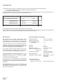
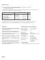
Technical Specifications for All Models
Ready for application after max. 10 Minutes
Ambient temperature +5 to 40 °C/ 50 °C
Factory set dew point 5°C
Protection class IP 20
Material of housing stainless steel
Packing dimensions appr. 350 mm x 220 mm x 220 mm
Weight including heat
exchanger(s) appr. 7,5 kg
at 24 V DC appr. 6 kg
Power supply 115 V AC, 230 V AC
or 24 V DC, 50/60 Hz
Power consumption max. 120 VA
Status output max. 230 V AC, 150 V DC
2A,50VA,dry
Potential-free
Electrical connectors
Standard applications
(PKE 511, 512, 521, 522) plugs according to DIN 43650
DE 44 0012
Page 2/4
02/2014
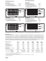
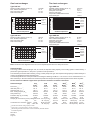
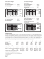
Application:
40 °C 50 °C
Standard
Max. ambient temperature:
1 heat exchange
2 heat exchanger
PKE 511 PKE 521
PKE 512 PKE 522
3rd no. = 1
3rd no. = 2
2nd no. = 1
2nd no. = 2

5 10152025303540°C50
0
20
40
60
80
120
5 1015 2025 303540
°C
50
0
20
40
60
80
120
5 1015202530
°C
35 40
kJ/h
kJ/h
0
20
40
50
80
120
5 10152025303540
°C
kJ/h
10
30
60
70
90
100
0
20
40
50
80
120
kJ/h
10
30
60
70
90
100
One heat exchanger
Type PKE 511
Nominal cooling capacity (at 25 °C) 100 kJ/h
Max. ambient temperature 40 °C
Drift over full range ± 1.5 K
Dew point noise static ± 0.1 K
Two heat exchangers
Type PKE 512
Nominal cooling capacity (at 25 °C) 100 kJ/h
Max. ambient temperature 40 °C
Dew point noise static ± 0.1 K
Drift over full range ± 1.5 K
Temperature differential between
heat exchangers < 0.5 K
Type PKE 521
Nominal cooling capacity (at 25 °C) 90 kJ/h
Max. Ambient temperature 50 °C
Dew point noise static ± 0.1 K
Drift over full range ± 1.5 K
Type PKE 522
Nominal cooling capacity (at 25 °C) 90 kJ/h
Max. Ambient temperature 50 °C
Dew point noise static ± 0.1 K
Drift over full range ± 1.5 K
Temperature differential between
heat exchangers < 0.5 K
Heat exchanger
The energy content of the sample gas and, as a result, the required cooling capacity of the cooling system is determined by 3
parameters: gas temperature , dew point (moisture content) and flow v.
The outlet dew point raises with increasing energy content (heat) of the gas. The required cooling capacity is determined by the
mximum acceptable level of the outlet dew point.
The following table shows cooler performance assuming the following conditions: =40°C and =70°C. Indicated is the v in
Nl/h cooled air (i.e. after the moisture has condensed). With other dew points and gas inlet temperatures the values may differ.
Jt
tJ
Ge
e G max
Please contact one of Buhler’s application specialists for assistance and further information.
Heat exchanger GPTS PTG PTV MTS MT MTV
PTS-I PTG PTV-I MTS-I MTG MTV-I
3) 3) 3)
2) 2) 2) 3) 3) 2) 3)
)
)
)
)
Flow rate v 450 l/h 250 l/h 250 l/h 300 l/h 210 l/h 190 l/h
Inlet dew point 65 °C 65 °C 65 °C 65 °C 65 °C 65 °C
Gas inlet temp. 180 °C 140 °C 140 °C 140 °C 140 °C 140 °C
Max. cooling capacity Q 150 kJ/h 90 kJ/h 90 kJ/h 95 kJ/h 80 kJ/h 65 kJ/h
Gas pressure p 160 bar 3 bar 2 bar 25 bar 3 bar 2 bar
Pressure drop p (v=150 l/h) 10 mbar 10 mbar 10 mbar 20 mbar 19 mbar 18 mbar
Dead volume 29 ml 29 ml 57 ml 19 ml 18 ml 17 ml
Swagelok 6 mm GL 14 DN 4/6 tube 6 mm GL14 (6 mm) DN 4/6
1/4” GL 14 (1/4”) 1/4”-1/6” tube 1/4” Gl14 (1/4”) 1/4”-1/6”
G 3/8“ GL 25 G3/8" G1/4” GL18 (8 mm) G 1/4”
NPT 3/8“ GL 25 (1/2”) NPT 3/8" NPT 1/4” GL18 (8 mm) NPT 1/4”
max
e,max
G,max
max
max
1)
1)
1)
4
4
4
4
1)
2)
3)
4)
t
J
D
Sample gas connections (metric) (6 mm)
(US)
Condensate out connection (metric) (12 mm)
(US)
Consider the maximum cooling capacity of cooler
Heat exchangers MTS, MTG and MTV cannot be drained by automatic drainers
Inner diameter gasket
Types marked “I” have NPT-threads or US tubes, respectively
Note: The limits in the diagrams for the PTG, PTV respectively MTV are for a dew point of 40°C.
DE 440012
Page 3/4
02/2014
limit for
2xMTV
PKE with
2xMTS
Ambient temperature
PKE with
PTS
limit for
PTG,PTV
Ambient temperature
PKE with
2xMTS
limit for
2xMTV
Ambient temperature
limit for
PTG,PTV
Ambient temperature
Cooling capacity
Cooling capacity
Cooling capacity
Cooling capacity
PKE with
PTS
limit for
2xMTG
limit for
2xMTG

4
4
4
4
6
6
0
0
0
0
5
11
521
1
2
3
1
2
0
1
512
522
1
3
1
2
0
2
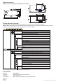
NETZ
POWER
ALARM-
AUSGANG
ALARM-
OUTPUT
ENTER
292
90
Ø7
114,5
105,5
98
112
165
165
153,5
310
140
150
130
A000138X
3
4
3
4
0
0
2
5
6
5
6
Types with one Heat Exchanger
PKE 511: Standard ambient temperature 40 °C
PKE 521: Standard ambient temperature 50 °C
115 V metric fittings
Power Supply
230 V metric fittings
Stainless steel / (PTS or PTS-I)
Glass / (PTG)
Material Heat Exchanger / Version
PVDF / (PTV or PTV-I)
Condensate Discharge
None
One peristaltic pump
Types with two Heat Exchangers
115 V metric fittings
Power Supply
230 V metric fittings
Stainless steel / (MTS or MTS-I)
Material Heat Exchanger / Version
PVDF / (MTV or MTV-I)
PKE 522: Standard ambient temperature 50 °C
Condensate Discharge (only 115 V / 230 V)
1)
PKE 512: Standard ambient temperature 40 °C
None
Two peristaltic pumps
1)
Heat exchangers MTS, MTG and MTV cannot be drained by automatic drainers
DE 440012
Page 4/4
02/2014
Accessories
Part No. Description
45 100 08 Automatic condensate drain type AK 5.2
44 100 05 Glass vessel GL 1
91 240 300 27 Spare tube for peristaltic pump, right angle terminals
Please indicate with order
Please extract the part number for the cooler fulfilling your requirements from the type code below.
: Each gas path should be equipped with a peristaltic pump or an automatic condensate drain. A peristaltic
pump cannot be installed at the factory in versions with 24 V mains supply.
Please note
We reserve the right to amend specification
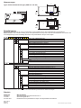
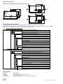
Dimensions (mm)
Models for standard applications (PKE 51x und 52x)
Air
In
Air
Out
Air
In
Air
Out
115 V US fittings
115 V US fittings
230 V US fittings
230 V US fittings
Glass / (MTG)
Part-no.
Part-no.
24 V DC metric fittings
24 V DC US fittings
24 V DC metric fittings
24 V DC US fittings

Sample Gas Cooler PKE 5
Accurate measurement of gases requires gas samples with
stable dew points even under harsh ambient conditions.
The PKE 5 is designed for moderate ambient and gas
temperatures (2.5 lpm at @ 158 °F) and an inlet dew point of
about 104 °F (approx. 5% vol). For higher ambient tempera-
tures up to a maximum of 122 °F order the PKE 52x.
The dew point of 41 °F is regulated by an electronic control-
ler. The temperature (in °F or °C) of the cooling block is
shown on an LED-display. The status is indicated by a
flashing display which shows high or low temperature and
operates together with a relay in fail-safe mode.
Condensate is removed by peristaltic pumps, automatic
condensate drains or condensate vessels.
The PKE Models feature a semiconductor Peltier cooling
system with an aluminum cooling block. Fitted into the block
is a removable high-efficiency heat exchanger made of
stainless steel, DURAN-glass or PVDF.
§
§
§
§
§
§
§
§
§
§
Compact design
Easy installation
No maintenance required
Low noise
Efficient heat exchangers made of
stainless steel, Duran glass or PVDF
Nominal cooling capacity 85/95 Btu/hr
Dew point stability 0.2 °F
Status display and output
Cooling temperature display
Model available for high ambient
temperatures
DA 44 0012
Page 1/4
02/2014
Buhler Technologies LLC
1030 West Hamlin Road, Rochester Hills, MI 48309
Phone: 248.652.1546 Fax: 248.652.1598
Internet: www.buhlertech.com
e-mail: [email protected]
Page is loading ...
Page is loading ...
Page is loading ...
Page is loading ...
Page is loading ...
-
 1
1
-
 2
2
-
 3
3
-
 4
4
-
 5
5
-
 6
6
-
 7
7
-
 8
8
-
 9
9
-
 10
10
-
 11
11
-
 12
12
-
 13
13
-
 14
14
-
 15
15
-
 16
16
-
 17
17
-
 18
18
-
 19
19
-
 20
20
-
 21
21
-
 22
22
-
 23
23
-
 24
24
-
 25
25
-
 26
26
-
 27
27
-
 28
28
-
 29
29
-
 30
30
-
 31
31
-
 32
32
-
 33
33
-
 34
34
-
 35
35
-
 36
36
-
 37
37
-
 38
38
-
 39
39
-
 40
40
-
 41
41
-
 42
42
-
 43
43
-
 44
44
-
 45
45
-
 46
46


Buhler PKE 511 Installation And Operation Instruction Manual
- Type
- Installation And Operation Instruction Manual
Ask a question and I''ll find the answer in the document
Finding information in a document is now easier with AI
in other languages
- Deutsch: Buhler PKE 511
Related papers
-
Buhler PKE 42 Installation And Operation Instruction Manual
-
-
-
-
-
-
-
-
-
Other documents
-
Vogel's PTS 1102 User manual
-
 ANKO 913-2450 User manual
-
ABB SCC-C User manual
-
Homa CTP 53 Series Original Instruction Manual
-
Bühler technologies Nivotemp NT M-L Series Installation And Operation Instructions Manual
-
Arctic MX-2 Installation guide
-
HEYLO DT 750 User manual
-
Buderus BUE-Plus Installation And Operating Instructions Manual
-
cleanAIR SGC4000 Maintenance Manual
-
German GPU-6SSM User manual
