Page is loading ...

User Guide
PowerCage FOX Tx / Rx VGA
PowerCage FOX Tx / Rx DVI
PowerCage FOX Tx / Rx DVI Plus
Fiber Optic Extenders
High Resolution Fiber Optic Transmitters and Receivers
68-1911-01 Rev. E
01 19

Safety Instructions
Safety Instructions • English
WARNING: This symbol, , when used on the product, is intended to
alert the user of the presence of uninsulated dangerous voltage within
the product’s enclosure that may present a risk of electric shock.
ATTENTION: This symbol, , when used on the product, is intended
to alert the user of important operating and maintenance (servicing)
instructions in the literature provided with the equipment.
For information on safety guidelines, regulatory compliances, EMI/EMF
compatibility, accessibility, and related topics, see the Extron Safety and
Regulatory Compliance Guide, part number 68-290-01, on the Extron
website, www.extron.com.
Sicherheitsanweisungen • Deutsch
WARNUNG: Dieses Symbol auf dem Produkt soll den Benutzer
darauf aufmerksam machen, dass im Inneren des Gehäuses dieses
Produktes gefährliche Spannungen herrschen, die nicht isoliert sind und
die einen elektrischen Schlag verursachen können.
VORSICHT: Dieses Symbol auf dem Produkt soll dem Benutzer in
der im Lieferumfang enthaltenen Dokumentation besonders wichtige
Hinweise zur Bedienung und Wartung (Instandhaltung) geben.
Weitere Informationen über die Sicherheitsrichtlinien, Produkthandhabung,
EMI/EMF-Kompatibilität, Zugänglichkeit und verwandte Themen finden Sie in
den Extron-Richtlinien für Sicherheit und Handhabung (Artikelnummer
68-290-01) auf der Extron-Website, www.extron.com.
Instrucciones de seguridad • Español
ADVERTENCIA: Este símbolo, , cuando se utiliza en el producto,
avisa al usuario de la presencia de voltaje peligroso sin aislar dentro del
producto, lo que puede representar un riesgo de descarga eléctrica.
ATENCIÓN: Este símbolo, , cuando se utiliza en el producto, avisa
al usuario de la presencia de importantes instrucciones de uso y
mantenimiento recogidas en la documentación proporcionada con el
equipo.
Para obtener información sobre directrices de seguridad, cumplimiento
de normativas, compatibilidad electromagnética, accesibilidad y temas
relacionados, consulte la Guía de cumplimiento de normativas y seguridad
de Extron, referencia 68-290-01, en el sitio Web de Extron, www.extron.com.
Instructions de sécurité • Français
AVERTISSEMENT : Ce pictogramme, , lorsqu’il est utilisé sur le
produit, signale à l’utilisateur la présence à l’intérieur du boîtier du
produit d’une tension électrique dangereuse susceptible de provoquer
un choc électrique.
ATTENTION : Ce pictogramme, , lorsqu’il est utilisé sur le produit,
signale à l’utilisateur des instructions d’utilisation ou de maintenance
importantes qui se trouvent dans la documentation fournie avec le
matériel.
Pour en savoir plus sur les règles de sécurité, la conformité à la
réglementation, la compatibilité EMI/EMF, l’accessibilité, et autres sujets
connexes, lisez les informations de sécurité et de conformité Extron, réf.
68-290-01, sur le site Extron, www.extron.com.
Istruzioni di sicurezza • Italiano
AVVERTENZA: Il simbolo, , se usato sul prodotto, serve ad
avvertire l’utente della presenza di tensione non isolata pericolosa
all’interno del contenitore del prodotto che può costituire un rischio di
scosse elettriche.
ATTENTZIONE: Il simbolo, , se usato sul prodotto, serve ad
avvertire l’utente della presenza di importanti istruzioni di funzionamento
e manutenzione nella documentazione fornita con l’apparecchio.
Per informazioni su parametri di sicurezza, conformità alle normative,
compatibilità EMI/EMF, accessibilità e argomenti simili, fare riferimento
alla Guida alla conformità normativa e di sicurezza di Extron, cod. articolo
68-290-01, sul sito web di Extron, www.extron.com.
Instrukcje bezpieczeństwa • Polska
OSTRZEŻENIE: Ten symbol, , gdy używany na produkt, ma na celu
poinformować użytkownika o obecności izolowanego i niebezpiecznego
napięcia wewnątrz obudowy produktu, który może stanowić zagrożenie
porażenia prądem elektrycznym.
UWAGI: Ten symbol, , gdy używany na produkt, jest przeznaczony do
ostrzegania użytkownika ważne operacyjne oraz instrukcje konserwacji
(obsługi) w literaturze, wyposażone w sprzęt.
Informacji na temat wytycznych w sprawie bezpieczeństwa, regulacji
wzajemnej zgodności, zgodność EMI/EMF, dostępności i Tematy pokrewne,
zobacz Extron bezpieczeństwa i regulacyjnego zgodności przewodnik, część
numer 68-290-01, na stronie internetowej Extron, www.extron.com.
Инструкция по технике безопасности • Русский
ПРЕДУПРЕЖДЕНИЕ: Данный символ, , если указан
на продукте, предупреждает пользователя о наличии
неизолированного опасного напряжения внутри корпуса
продукта, которое может привести к поражению электрическим
током.
ВНИМАНИЕ: Данный символ, , если указан на продукте,
предупреждает пользователя о наличии важных инструкций
по эксплуатации и обслуживанию в руководстве,
прилагаемом к данному оборудованию.
Для получения информации о правилах техники безопасности,
соблюдении нормативных требований, электромагнитной
совместимости (ЭМП/ЭДС), возможности доступа и других
вопросах см. руководство по безопасности и соблюдению
нормативных требований Extron на сайте Extron: ,
www.extron.com, номер по каталогу - 68-290-01.
安全说明 • 简体中文
警告: 产品上的这个标志意在警告用户该产品机壳内有暴露的危险 电压,
有触电危险。
注意: 产品上的这个标志意在提示用户设备随附的用户手册中有
重要的操作和维护(维修)说明。
关于我们产品的安全指南、遵循的规范、EMI/EMF 的兼容性、无障碍
使用的特性等相关内容,敬请访问 Extron 网站 , www.extron.com,参见
Extron 安全规范指南,产品编号 68-290-01
。

安全記事 • 繁體中文
警告: 若產品上使用此符號,是為了提醒使用者,產品機殼內存在著
可能會導致觸電之風險的未絕緣危險電壓。
注意 若產品上使用此符號,是為了提醒使用者,設備隨附的用戶手冊中有
重要的操作和維護(維修)説明。
有關安全性指導方針、法規遵守、EMI/EMF 相容性、存取範圍和相關主題的詳細資
訊,請瀏覽 Extron 網站:www.extron.com,然後參閱《Extron 安全性與法規
遵守手冊》,準則編號 68-290-01。
安全上のご注意
• 日本語
警告: この記号 が製品上に表示されている場合は、筐体内に絶縁されて
いない高電圧が流れ、感電の危険があることを示しています。
注意:この記号 が製品上に表示されている場合は、本機の取扱説明書
に 記載されている重要な操作と保守(整備)の指示についてユーザーの
注意を喚起するものです。
安全上のご注意、法規厳守、EMI/EMF適合性、その他の関連項目に
つ い て は 、エ ク スト ロ ン の ウェ ブ サ イト www.extron.com よ り 『 Extron Safety
and Regulatory Compliance Guide』 ( P/N 68-290-01) をご覧ください。
안전 지침 • 한국어
경고: 이 기호 가 제품에 사용될 경우, 제품의 인클로저 내에 있는
접지되지 않은 위험한 전류로 인해 사용자가 감전될 위험이 있음을
경고합니다.
주의: 이 기호 가 제품에 사용될 경우, 장비와 함께 제공된 책자에 나와
있는 주요 운영 및 유지보수(정비) 지침을 경고합
니다.
안전 가이드라인, 규제 준수, EMI/EMF 호환성, 접근성, 그리고 관련 항목에
대한 자세한 내용은 Extron 웹 사이트(www.extron.com)의 Extron 안전 및
규제 준수 안내서, 68-290-01 조항을 참조하십시오.
Copyright
© 2019 Extron Electronics. All rights reserved.
Trademarks
All trademarks mentioned in this guide are the properties of their respective owners.
The following registered trademarks®, registered service marks(
SM
), and trademarks(
TM
) are the property of RGBSystems, Inc. or Extron
Electronics (see the current list of trademarks on the Terms of Use page at www.extron.com):
Registered Trademarks
(®)
AVTrac, Cable Cubby, CrossPoint, DTP, eBUS, EDID Manager, EDID Minder, Extron, Flat Field, FlexOS, Global Configurator, GlobalViewer, Hideaway,
Inline, IP Intercom, IP Link, Key Minder, LinkLicense, LockIt, MediaLink, MediaPort, NetPA, PlenumVault, PoleVault, PowerCage, Pure3, Quantum,
SoundField, SpeedMount, SpeedSwitch, System INTEGRATOR, TeamWork, TouchLink, V-Lock, VersaTools, VN-Matrix, VoiceLift, WallVault, WindoWall,
XTP, and XTP Systems
Registered Service Mark
(SM)
: S3 Service Support Solutions
Trademarks
(
™
)
AAP, AFL (Accu-RATE Frame Lock), ADSP (Advanced Digital Sync Processing), Auto-Image, CableCover, CDRS (Class D Ripple Suppression), DDSP
(Digital Display Sync Processing), DMI (Dynamic Motion Interpolation), Driver Configurator, DSP Configurator, DSVP (Digital Sync Validation Processing),
DTP, eLink, EQIP, FastBite, FOX, FOXBOX, IP Intercom HelpDesk, MAAP, MicroDigital, ProDSP, QS-FPC (QuickSwitch Front Panel Controller),
Room Agent, Scope-Trigger, ShareLink, SIS, Simple Instruction Set, Skew-Free, SpeedNav, Triple-Action Switching, True4K, Vector™ 4K, WebShare,
XTRA, ZipCaddy, and ZipClip

FCC Class A Notice
This equipment has been tested and found to comply with the limits for a Class A digital device,
pursuant to part15 of the FCC rules. The ClassA limits provide reasonable protection against harmful
interference when the equipment is operated in a commercial environment. This equipment generates,
uses, and can radiate radio frequency energy and, if not installed and used in accordance with the
instruction manual, may cause harmful interference to radio communications. Operation of this
equipment in a residential area is likely to cause interference. This interference must be corrected at
the expense of the user.
NOTE: For more information on safety guidelines, regulatory compliances, EMI/
EMF compatibility, accessibility, and related topics, see the “Extron Safety and
Regulatory Compliance Guide” on the Extron website.
Class 1 Laser Product
Any service to this product must be carried out by Extron Electronics and its qualified
service personnel.
CAUTION: Using controls, making adjustments, or performing procedures in a manner
other than what is specified herein may result in hazardous radiation exposure.
NOTE: For more information on safety guidelines, regulatory compliances,
EMI/EMF compatibility, accessibility, and related topics, see the “Extron Safety and
Regulatory Compliance Guide” on the Extron website.
Produit laser de classe1
Si ce produit a besoin d’un quelconque entretient, celui-ci doit être fait par
ExtronElectronics et son personnel qualifié.
ATTENTION : L’utilisation de commandes, la réalisation de réglages, ou l’exécution de
procédures de manière contraire aux dispositions établies dans le présent document,
présente un risque d’exposition dangereuse aux radiations.
Remarque : Pour plus d'informations sur les directives de sécurité, les conformités
de régulation, la compatibilité EMI/EMF, l'accessibilité, et les sujets en lien, consultez le
«Informations de sécurité et de conformité Extron» sur le site internet d'Extron.

Conventions Used in this Guide
Notifications
The following notifications are used in this guide:
WARNING: Potential risk of severe injury or death.
AVERTISSEMENT :
Risque potentiel de blessur
e grave ou de mort.
CAUTION: Risk of minor personal injury.
ATTENTION :
Risque de blessur
emineure.
ATTENTION:
•
Risk of pr
operty damage.
•
Risque de dommages matériels.
NOTE: A note draws attention to important information.
TIP: A tip provides a suggestion to make working with the application easier.
Software Commands
Commands are written in the fonts shown here:
^AR Merge Scene,,Op1 scene 1,1 ^B 51 ^W^C
[01]
R
0004
00300
00400
00800
00600
[02]
35
[17] [03]
E X! *X1&* X2!* X2%* X2# CE}
NOTE: For commands and examples of computer or device responses mentioned
in this guide, the character “0” is used for the number zero and “O” is the capital
letter “o.”
Computer responses and directory paths that do not have variables are written in the font
shown here:
Reply from 208.132.180.48: bytes=32 times=2ms TTL=32
C:\Program Files\Extron
Variables are written in slanted form as shown here:
ping xxx.xxx.xxx.xxx —t
SOH R Data STX Command ETB ETX
Selectable items, such as menu names, menu options, buttons, tabs, and field names are
written in the font shown here:
From the File menu, select New.
Click the OK button.
Specifications Availability
Product specifications are available on the Extron website, www.extron.com.
Extron Glossary of Terms
A glossary of terms is available at http://www.extron.com/technology/glossary.aspx.


viiPowerCage FOX DVI and PowerCage FOX VGA • Contents
Introduction ...................................................1
About this Guide ................................................. 1
About the PowerCage FOX Transmitters and
Receivers .......................................................... 2
General System Operation .............................. 3
System Compatibility ...................................... 4
Cable Transmission Modes ............................. 5
Features ............................................................. 5
Installation and Operation ........................... 7
Mounting the Units ............................................. 7
Connections and Indications ............................... 7
Making Connections ..................................... 13
PowerCage Front Panel Port, Control, and
Indicators ........................................................ 15
Operation ......................................................... 17
Remote Control ...........................................18
Serial Ports ....................................................... 18
Simple Instruction Set Control .......................... 19
Host-to-Switcher Communications ............... 19
Symbol Definitions ........................................ 19
Unit-initiated Messages................................. 20
Error Responses .......................................... 21
Timeout ........................................................ 21
Using the Command and Response Table .... 21
FOX Extenders Control Program ....................... 26
Installing the Software ................................... 26
Starting the Program .................................... 27
Updating the Firmware ................................. 32
PowerCage Enclosure ................................ 37
Installing a Board in the Enclosure .................... 37
Contents

PowerCage FOX DVI and PowerCage FOX VGA • Contents viii

PowerCage FOX DVI and PowerCage FOX VGA • Introduction 1
Introduction
WARNING: The PowerCage FOX outputs continuous invisible light (Class 1 rated),
which may be harmful to the eyes; use with caution.
•
Do not look into the r
ear panel fiber optic cable connectors or into the fiber optic
cables themselves.
•
Plug the attached dust cap into the optical transceiver when the fiber optic cable is
unplugged.
A
VERTISSEMENT :
Le PowerCage FOX émet une lumièr
e invisible en continu
(conforme à la classe1) qui peut être dangereux pour les yeux, à utiliser avec
précaution.
•
Ne r
egardez pas dans les connecteurs de câble fibre optique sur le panneau arrière
ou dans les câbles fibre optique eux-mêmes.
•
Branchez la pr
otection contre la poussière dans l’ensemble émetteur/récepteur
lorsque le câble fibre optique est débranché.
•
About this Guide
•
About the PowerCage FOX T
ransmitters and Receivers
•
Featur
es
About this Guide
This guide contains information about the following Extron PowerCage FOX family of
modular board-designed fiber optic transmitters and receivers for the PowerCage Modular
Power Enclosures:
• PowerCage FOX Tx VGA transmitter
• PowerCage FOX Rx VGA receiver
• PowerCage FOX Tx DVI (non-Plus) transmitter
•
PowerCage FOX Rx DVI (non-Plus) r
eceiver
•
PowerCage FOX Tx DVI Plus transmitter
•
PowerCage FOX Rx DVI Plus r
eceiver
This guide includes instructions for an experienced installer to install, configure, and operate
the equipment.
NOTES:
• In this manual, “PowerCage FOX” refers to either an analog RGB video or a DVI
video unit. Where differences exist between the VGA and DVI models, the full name
of the unit is used.
• In this manual, “PowerCage FOX DVI” refers to either the Plus or non-Plus model,
unless a model is specifically named.

PowerCage FOX DVI and PowerCage FOX VGA • Introduction 2
PowerCage 1600
Power Supply
1 2
REMOTE
RS-232
RS-232
OVER FIBER
Tx Rx
Tx
ALARM
Rx
INPUT
PowerCage
FOX Tx DVI
Tx Rx
LR
AUDIO
DVI
1 2
REMOTE
RS-232
RS-232
OVER FIBER
Tx Rx
Tx
ALARM
Rx
INPUT
PowerCage
FOX Tx DVI
Tx Rx
LR
AUDIO
DVI
5A MAX.
100-240V 50/60Hz
N15778
1T23
I.T.E.
Extr
on
Powe
rCage 1600
FOXBOX Rx DVI Plus
DVI
OVER
TEMP
AUDIO
CONFIG
OPTICAL
Rx
Tx
LINK
LINK
AUDIO
DVI-D OUTPUT
FOXBOX Rx DVI Plus
RS-232
OVER FIBER
ALARM
Tx Rx 1 2
12V
1.0A MAX
POWER
MODE
1
ON
2
FOXBOX 4G Rx DVI Plus
DVI
OVER
TEMP
AUDIO
CONFIG
OPTICAL
Rx
Tx
LINK
LINK
AUDIO
DVI-D OUTPUT
FOXBOX 4G Rx DVI Plus
RS-232
OVER FIBER
ALARM
Tx Rx 1 2
12V
1.0A MAX
POWER
MODE
1
ON
2
Flat Panel Displa
ys
Fiber
DVI
DVI
FOXBOX DVI Plus
Receivers
PC PC
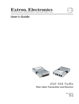
Figure 1. Typical PowerCage FOX Tx/Rx Application
About the PowerCage FOX Transmitters and Receivers
The PowerCage consists of several sets of ultra-high performance fiber optic transmitters
and receivers:
• PowerCage FOX Tx VGA transmitter — Accepts an analog RGB video input, an
audio input, and an RS-232 serial input. The transmitter outputs a proprietary optical
signal on an LC connector to a PowerCage FOX, FOXBOX, or FOX 500 receiver. It also
can receive a proprietary optical signal from the receiver consisting of the RS-232 return
from a controlled device.
•
PowerCage FOX Rx VGA r
eceiver — Accepts a proprietary optical signal on an LC
connector from a PowerCage FOX, FOXBOX, or FOX 500 transmitter or daisy-chained
PowerCage FOX or PowerCage FOX receiver. The receiver outputs analog RGB video,
audio, and RS-232 serial commands. It also can either:
• Receive an RS-232 return from a controlled device and send it to the transmitter via
a proprietary optical signal, or
• Output a daisy-chained signal to another receiver.
•
PowerCage FOX Tx DVI Plus transmitter
— Accepts a single link of DVI video
input (up to 1920 x 1200 at 60 Hz), an audio input, and an RS-232 serial input. The
transmitter outputs a proprietary optical signal on an LC connector to a PowerCage
FOX Rx DVI Plus or FOXBOX Rx DVI Plus receiver only. It also can receive a proprietary
optical signal from the receiver consisting of the RS-232 return from a controlled device.
•
PowerCage FOX Tx DVI (non-Plus) transmitter
— Similar to PowerCage FOX TX
DVI Plus, but with a lower maximum resolution (1600x1200 or 1080p @ 60 Hz) and a
different proprietary output that is compatible with all PowerCage FOX, FOXBOX, or
FOX 500 receivers.

PowerCage FOX DVI and PowerCage FOX VGA • Introduction 3
• PowerCage FOX Rx DVI Plus receiver — Accepts a proprietary optical signal
on an LC connector from a PowerCage FOX, FOXBOX, or FOX 500 transmitter or
daisy-chained receiver. The receiver outputs a single link of DVI video, audio, and
RS-232 serial commands. It also can either:
• Receive an RS-232 return from a controlled device and send it to the transmitter via
a proprietary optical signal, or
• Output a daisy-chained signal to another receiver.
• PowerCage FOX Rx DVI (non-Plus) receiver — Similar to the PowerCage
FOX RX DVI Plus, but with lower maximum resolution (1600x1200 or 1080p @ 60 Hz)
and receiving a different proprietary input. Discontinued, but included in this list for
reference only.
General System Operation
• The PowerCage FOX VGA transmitter inputs VGA-UXGA RGB video.
•
The PowerCage FOX DVI Plus transmitter inputs a single link of DVI video.
Both transmitters input audio and one-way (transmitter
-to-receiver) RS-232 serial
communication (for applications such as projector control). The transmitters convert
all of the inputs to them into a proprietary signal and output the signal on a single fiber
optic cable to the receiver. An optional return (receiver-to-transmitter) stream of serial
RS-232 communications, such as projector responses, requires a second fiber optic
cable. Rather than the return RS-232 communications, the receivers can be configured
to output a daisy-chained primary fiber optic signal to another receiver.
• The PowerCage FOX VGA receiver outputs VGA-UXGA RGB video.
• The PowerCage FOX DVI receiver outputs a single link of DVI video.
The receivers convert the proprietary signal back to video (either RGB or DVI as
applicable to the model), audio, and serial RS-232 communication, and output
the signals locally. If either RS-232 return or daisy-chained communications are
implemented (a second fiber optic cable is installed), the receiver outputs a proprietary
signal on the second fiber optic cable. For video resolutions up to 1600 x 1200 or
1080p, the video output of the receiver is a perfect, pixel-for-pixel recreation of the video
signal input to the transmitter.
The PowerCage FOX VGA transmitter can handle an RGBHV, RGBS, RGsB, or RsGsBs
input signal. The PowerCage FOX VGA receiver can output RGBHV or RGsB, as selected
by the user.
The transmitter and receiver have image and audio adjustments available under RS-232
control. Both units have fiber light status indicators and lost-light alarm connectors.
The receivers have built-in alternating pixels, color bars, and grayscale test patterns to assist
in setting up the display equipment.

PowerCage FOX DVI and PowerCage FOX VGA • Introduction 4
System Compatibility
The fiber optic signal output from a PowerCage FOX Tx DVI Plus transmitter can be received
only by a PowerCage FOX Rx DVI Plus or FOXBOX Rx DVI Plus receiver.
The fiber optic signals from all other units are interchangeably compatible between VGA and
DVI units, Plus and non-Plus units, and PowerCage FOX, FOXBOX, and FOX 500 units as
shown in the following table.
Receiver Compatible transmitters
PowerCage FOX Rx VGA PowerCage FOX Tx VGA
PowerCage FOX Tx DVI (non-Plus)
FOXBOX Tx VGA
FOXBOX Tx DVI (non-Plus)
FOX 500 Tx (VGA)
FOX 500 Tx DVI
FOX 500 DA6
PowerCage FOX Rx DVI Plus PowerCage FOX Tx DVI Plus
PowerCage Tx DVI (non-Plus)
PowerCage FOX Tx VGA
FOXBOX Tx DVI Plus
FOXBOX Tx DVI (non-Plus)
FOXBOX Tx VGA
FOX 500 Tx (VGA)
FOX 500 Tx DVI
FOX 500 DA6
PowerCage FOX Rx DVI (non-Plus) PowerCage FOX Tx DVI (non-Plus)
PowerCage FOX Tx VGA
FOXBOX Tx DVI (non-Plus)
FOXBOX Tx VGA
FOX 500 Tx (VGA)
FOX 500 Tx DVI
FOX 500 DA6
NOTES:
•
The PowerCage FOX units ar
e fully compatible with all Extron PowerCage FOX,
FOXBOX, and FOX 500 products and a variety of other fiber optic products. Those
other products are identified where appropriate, but not specifically described in this
manual.
•
The PowerCage FOX DVI does not support the transmission of signals with
High-bandwidth
Digital Content Protection (HDCP).

PowerCage FOX DVI and PowerCage FOX VGA • Introduction 5
Cable Transmission Modes
The transmitters and receivers are further categorized by the type of fiber optic cable,
multimode or singlemode, which define the effective range of transmission:
• Multimode — Long distance, up to 2 km (6,560 feet) (depending on the fiber cable)
• PowerCage FOX Tx VGA MM
• PowerCage FOX Rx VGA MM
• PowerCage FOX Tx DVI (Plus and non-Plus) MM
• PowerCage FOX Rx DVI (Plus and non-Plus) MM
• Singlemode — Very long distance, up to 30 km (18.75 miles)
• PowerCage FOX Tx VGA SM
• PowerCage FOX Rx VGA SM
• PowerCage FOX Tx DVI (Plus and non-Plus) SM
• PowerCage FOX Rx DVI (Plus and non-Plus) SM
NOTE: The multimode and singlemode products are physically and functionally
identical, with the exception of the effective range of transmission. In this manual,
any reference applies to either transmission mode unless otherwise specified.
Features
• Ultra high performance — Offers pixel-for-pixel RGBHV video or DVI video
transmission, up to 1920 x 1200 at 60 Hz (PowerCage FOX DVI Plus models) or 1600 x
1200 at 60 Hz.
• Video input —
• PowerCage FOX VGA — The transmitter accepts RGBHV, RGBS, RGsB, or
RsGsBs on a 15-pin HD connector.
• PowerCage FOX DVI — The transmitter accepts a single link of DVI-D video on a
DVI-I connector.
• EDID emulation mode (PowerCage FOX Tx DVI only) — The PowerCage FOX
DVI transmitter provides a function, under RS-232 control, for specifying the rate
of the incoming DVI signal. EDID emulation mode allows proper operation when no
local monitor is present.
• Video output —
• PowerCage FOX VGA — The receiver outputs RGBHV or RGsB (user-selectable)
on a 15-pin HD connector.
• PowerCage FOX DVI — The receiver outputs a single link of DVI-D video on a
DVI-I connector.
• PowerCage FOX VGA and PowerCage FOX DVI are mutually compatible
— This enables ultra-long distance DVI-to-analog RGB and analog RGB-to-DVI
conversion without the need for extra signal conversion devices.
• Compatibility with FOX 500 DA6 distribution amplifier and Fiber Matrix 6400
matrix switcher
• Audio input — The transmitters accept a balanced or unbalanced stereo audio input
on a 3.5 mm, 5-pole captive screw terminal.
• Audio input gain/attenuation — The input audio level can be adjusted within a range
of -18 dB (attenuation) to +10 dB (gain) via the RS-232 link.

PowerCage FOX DVI and PowerCage FOX VGA • Introduction 6
• Audio output — The receivers output balanced or unbalanced stereo audio on a 3.5
mm, 5-pole captive screw terminal.
• Links monitoring — The front panels of the transmitters and receivers have indicators
for monitoring both fiber optic links.
• Loss-of-light alarms — The rear panels of the transmitters and receivers have
discrete outputs that indicate if either of the fiber optic links have suffered a loss of the
light signal.
• FOX Extenders control program — For RS-232 remote control from a PC running
Windows
®
, the Extron FOX Extenders control software provides a graphical interface
and drag-and-drop, point-and-click operation.
• Simple Instruction Set (SIS) — The transmitters and receivers use the SIS for easy
remote control operation.
• Audio level — The audio output can be set to either the consumer level (-10 dBV) or
professional level (+4 dBu) from the front panel or under RS-232 control.
• Upgradable firmware — The firmware that controls the operation of each unit can be
upgraded in the field via the Configuration port on the PowerCage enclosure without
taking the unit out of service. Firmware upgrades are available for download on the
Extron website, and they can be installed using the FOX Extenders control program.
• Memory presets — 30 memory presets let you store input size and position settings
relative to a specific input resolution. You can then recall those settings, when needed,
using the SIS or the control software.
• PowerCage mounting — All PowerCage FOX Tx and Rx units are mountable in any
Extron PowerCage enclosure.

PowerCage FOX DVI and PowerCage FOX VGA • Installation and Operation 7
Installation and
Operation
This section describes the installation and operation of the PowerCage FOX VGA and
PowerCage FOX DVI, including:
• Mounting the Units
• Connections and Indications
• PowerCage Front Panel Port, Control, and Indicators
•
Operation
Mounting the Units
The PowerCage FOX transmitter or receiver must be installed in an Extron PowerCage
enclosure (see Installing a Board in the Enclosure on page 37.)
Connections and Indications
FOXBOX Tx VGA Rear Panel
FOXBOX Tx DVI Plus Rear Panel
Front Panel
Front Panel
FOXBOX Tx VGA
RGB
OVER
TEMP
AUDIO
CONFIG
OPTICAL
Rx
Tx
LINK
LINK
AUDIO
RGB INPUT
FOXBOX Tx VGA
RS-232
OVER FIBER
ALARM
Tx Rx 1 2
12V
1.0A MAX
POWER
DVI
OVER
TEMP
AUDIO
CONFIG
OPTICAL
Rx
Tx
LINK
LINK
AUDIO
DVI-D INPUT
RS-232
OVER FIBER
ALARM
Tx Rx 1 2
FOXBOX Tx DVI Plus
FOXBOX Tx DVI Plus
12V
1.0A MAX
POWER
AA
GGCC DD EE
DD EE
HH II
GGBB CCHH II
FF
FF
Figure 2. PowerCage FOX Tx and Rx Transmitter and Receiver Connectors
A
RGB Input port (see page 8)
G
Optical port and LEDs (see page 10)
B
DVI Input port (see page 8)
H
Optical port and LEDs (see page 11)
C
Audio Input port (see page 8)
I
RGB Output port (see page 12)
D
RS-232 Over Fiber port (see page 9)
J
DVI Output port (see page 12)
E
Remote RS-232 port (see page 9)
K
Audio Output port (see page 12)
F
Alarm Outputs port (see page 9)
L
Power Indicator LED (see page 12)

PowerCage FOX DVI and PowerCage FOX VGA • Installation and Operation 8
A
RGB Input port (PowerCage FOX VGA only) (see figure 2 on the previous page) —
Connect an analog VGA-UXGA RGB video source to this 15-pin HD female connector.
B
DVI Input port (PowerCage FOX DVI only) — Connect a single link of DVI-D to
this DVI-I connector (see DVI connector (PowerCage FOX DVI) on page 12 for pin
assignments.)
NOTE: The PowerCage FOX DVI accepts only the digital signals on the DVI-I Input
connector. The analog pins on the port are not connected.
C
Audio Input port (transmitters) — Connect a balanced or unbalanced stereo or
mono audio input to this connector. The connector is included with transmitter, but
you must supply the audio cable (see figure 3 to wire a captive screw connector for
the appropriate input type). Use the supplied tie-wrap to strap the audio cable to the
extended tail of the connector.
LR
Unbalanced Stereo Input
Balanced Stereo Input
Ring
Sleeve (s)
Tip
Sleeve
Tip
Sleeve
Tip
Tip
Ring
Do not tin the wires!
Figure 3. Captive Screw Connector Wiring for Stereo Audio Input
NOTES:
•
The length of exposed wir
es is important. The ideal length is 3/16 inch (5 mm).
•
If the stripped section of wir
e is longer than 3/16 inch, the exposed wires
may touch, causing a short circuit.
•
If the stripped section of wir
e is shorter than 3/16 inch, wires can be easily
pulled out even if tightly fastened by the captive screws.
• Figure 4 identifies the tip, ring, and sleeve. A mono audio connector consists
of the tip and sleeve. A stereo audio connector consists of the tip, ring, and
sleeve. The tip, ring, and sleeve wires are also shown on the captive screw
audio connector diagrams (see figure 3, above, and figure 7 on page 12).
Tip (L+) Sleeve (Gnd)
Tip (L+)
Ring (R+)
Sleeve (Gnd)
Figure 4. Typical Audio Connectors
The input audio level can be set via RS-232 control (see Remote Control, beginning
on page 18).

PowerCage FOX DVI and PowerCage FOX VGA • Installation and Operation 9
D
RS-232 Over Fiber port (see figure 2 on page 7) — If you want the
RS-232
O
VER FIBER
Tx Rx
transmitter and receiver system to pass serial command signals for serial
control of a projector for example, connect the host device to the transmitter
and the slave device to the receiver via the first three poles on the left (Tx,
Rx, and _) of these 5-pole captive screw connectors on both units (see RS-232
connections on page 14 to wire this connector.
NOTES:
•
If you
connect only one fiber optic cable (see item
G
on the next page), or you
configure the receiver for daisy-chaining, you do not receive reports from the
controlled device. To receive responses from the controlled device, you must
install two fiber optic cables and leave the receiver in normal mode (via an SIS
command for the PowerCage FOX Rx receiver.)
•
The PowerCage FOX can pass RS-232 commands and r
esponses at rates up
to 115200 baud.
E
Remote RS-232 port — For serial control of the transmitter and receiver,
ALARM
Tx Rx 1 2
RS-232
OVER FIBE
R
connect a host device, such as a computer, to either unit via three poles
(Tx, Rx, and _) of this 5-pole captive screw connector on either unit (see
RS-232 connections on page 14 to wire this connector.)
See Remote Control, beginning on page 18 for definitions of the SIS commands (serial
commands to control the transmitter via this connector).
F
Alarm port — For remote monitoring of the status of the Rx fiberoptic link,
ALARM
Tx Rx 1 2
RS-232
OVER FIBER
connect a locally-constructed or furnished monitoring device to the unit to be
monitored via two poles of this 5-pole captive screw connector on the unit to
b
e monitored. When the unit does not detect light on its Rx connector, pin
1 and pin 2 of this port are shorted together (see Alarm connection on page 14).

PowerCage FOX DVI and PowerCage FOX VGA • Installation and Operation 10
G
Transmitter fiber optic port and LEDs (see figure 2 on page 7) —
WARNING: The PowerCage FOX Tx/Rx outputs continuous invisible light (Class 1
rated), which may be harmful to the eyes; use with caution. Plug the attached
dust cap into the optical transceiver when the fiber optic cable is unplugged.
AVERTISSEMENT :
Le PowerCage FOX Tx/Rx émet une lumièr
e invisible en
continu (conforme à la classe1) qui peut être dangereux pour les yeux, à utiliser
avec précaution Branchez la protection contre la poussière dans l’ensemble
émetteur/récepteur lorsque le câble fibre optique est débranché.
NOTES:
•
Ensur
e that you use the proper fiber cable for your transmitter-receiver pair.
Typically, singlemode fiber has a yellow jacket and multimode cable has an
orange or aqua jacket.
•
Only one fiber optic cable, transmitter
-Tx-to-receiver-Rx, is required for video,
audio, and serial command transmission. But, if you connect only one fiber
optic cable, or if your transmitter is configured to daisy-chain the optical signal,
system functionality is reduced. You will not receive RS-232 reports from the
controlled device, and some Windows-based control program functions and
RS-232 commands will not work. To receive responses from the controlled
device and for full functionality, install both fiber optic cables and leave the
receiver in normal mode (via an SIS command for the PowerCage FOX Rx
receiver.)
Ô
Tx (required) — For all one-way video, audio, and serial
communications from the transmitter to the receiver, connect a
fiber optic cable to the Tx LC connector.
Connect the free end of this fiber optic cable to the Rx connector
(see item
H
on the next page) on the PowerCage FOX Rx
receiver or to any other compatible Extron FOX device.
Û
Rx (optional) — Connect a fiber optic cable for all one-way return
serial communications from the receiver to the transmitter.
Connect the free end of this fiber optic cable to the Tx connector
(item
H
) on the PowerCage FOX Rx receiver in normal mode or
to any other compatible Extron FOX device.
Tx and Rx LEDs — When Tx or Rx is lit, the associated link is
active (light is received).
Tr
ansmitter
to
Receiver
OPTICAL
Rx
Tx
LINK
LINK
OPTICAL
Rx
Tx
LINK
LINK
1
122

PowerCage FOX DVI and PowerCage FOX VGA • Installation and Operation 11
H
Receiver fiber optic port and LEDs (see figure 2 on page 7) —
WARNING: The PowerCage FOX Tx/Rx outputs continuous invisible light (Class 1
rated), which may be harmful to the eyes; use with caution. Plug the attached
dust cap into the optical transceiver when the fiber optic cable is unplugged.
AVERTISSEMENT :
Le PowerCage FOX Tx/Rx émet une lumièr
e invisible en
continu (conforme à la classe1) qui peut être dangereux pour les yeux, à utiliser
avec précaution Branchez la protection contre la poussière dans l’ensemble
émetteur/récepteur lorsque le câble fibre optique est débranché.
NOTES:
•
Y
ou can connect the transmitter to one or more receivers in one of three ways:
•
O
ne way (transmitter-Tx-to-receiver-Rx) only — Connect fiber cable
h
(from transmitter connector
Ô
) only.
•
T
wo way (transmitter to receiver and return) — Connect fiber cable
h
(from transmitter connector
Ô
) and fiber cable
h
back to the transmitter
(connector
Û
) (see figure 5.)
•
One way (transmitter to r
eceiver) with daisy chain
(receiver to receiver) — Connect fiber cable
h
from a
fiber optic source and cable
h
to the next receiver in the
daisy chain (see figure 6.) Set each receiver in the daisy
chain to daisy chain mode (via an SIS command for the
PowerCage FOX Rx receiver.)
Up to 10 properly-configured receivers can be connected
in a daisy chain to a single transmitter.
• See the transmitter fiber connector NOTES on page 10,
which also apply to these connectors.
Fr
om Transmitter
or Daisy-Chained
Receiver
Receiver
Receive
r
Tx Rx
Tx Rx
33
33
44
Figure 6. Daisy Chain Configuration
h
Rx (required) — For all one-way video, audio, and serial communications from the
transmitter to the receiver, connect a fiber optic cable to the Rx LC connector.
Connect the free end of this fiber optic cable to the Tx connector on the
PowerCage FOX Tx transmitter (see item
Ô
on page 9) or to any other compatible
Extron fiber optic device.
h
Tx (optional) — Connect a fiber optic cable to the Tx LC connector for either of
the following functions:
Normal configuration — For all one-way return serial communications from the
receiver to the Rx connector on the transmitter (see figure 5.)
Daisy chain configuration — For daisy-chained video, audio, and serial
communications to the Rx connector on another receiver (see figure 6.)
NOTE: The Tx connector emits light in either case and the Rx port receives light.
Connect the free end of this fiber optic cable to either:
• The Rx connector on the PowerCage FOX Tx transmitter (see item
Û
on page 9)
or to any other compatible Extron fiber optic device.
• The Rx connector on another receiver in the daisy chain.
Tx and Rx LEDs — When Tx or Rx is lit, the associated link is active.
Figure 5. Two Way
Configuration
Tr
ansmitter
( on
page 10)
Receiver
( on
page 10)
Tx Rx
Tx Rx
1
122
4
43
3

PowerCage FOX DVI and PowerCage FOX VGA • Installation and Operation 12
I
RGB Output port (PowerCage FOX Rx VGA only) (see figure 2 on page 7) —
Connect an analog VGA-UXGA RGB video display to this 15-pin HD female connector.
NOTE: You can set the receiver to output the desired video format: RGBHV or
RGsB. RGBHV is the default (see Remote Control, beginning on page 18.)
J
DVI Output port (PowerCage FOX DVI only) — Connect a DVI video display to this
DVI-I connector (see DVI connector (PowerCage FOX DVI) on the next page for pin
assignments).
NOTE: The PowerCage FOX DVI outputs only the digital signals on the DVI-I Output
connector. The analog pins on the port are not connected.
K
Audio Output port (receivers) — This 5-pole, 3.5 mm captive screw connector
outputs the transmitted, unamplified, line level audio. Connect audio devices, such as
an audio amplifier or powered speakers.
See figure 7 to properly wire a captive screw output connector. Use the supplied tie-
wrap to strap the audio cable to the extended tail of the connector.
Ring
Sleeve(s)
Tip
Tip
Ring
Sleeve(s)
Tip
Tip
Unbalanced Stereo Output Balanced Stereo Output
NO GROUND HERE.
NO GROUND HERE.
LR
Do not tin the wires!
Figure 7. Captive Screw Connector Wiring for Stereo Audio Output
ATTENTION:
• For unbalanced audio, connect the sleeves to the ground contact.
DO NOT connect the sleeves to the negative (-) contacts.
•
Pour l’audio asymétrique, connectez les manchons au contact au sol.
Ne PAS connecter les manchons aux contacts négatifs (–).
NOTE: The length of exposed wires is important. The ideal length is 3/16 inch (5 mm)
(see the audio input connector NOTES on page 8 for more information.)
The volume level for the output can be set to either the consumer line level (-10 dBV) or
the professional line level (+4 dBu) via RS-232 control (see Remote Control, beginning
on page 18 for details).
L
Power LED — This LED lights to indicate that power is applied to the unit.
/