Page is loading ...

SM-302688-A/3
INSTRUCTION MANUAL
Quick Valve
2QV・3QV Series
● Please read this instruction manual
carefully before using this product,
particularly the section describing safety.
● Retain this instruction manual with the
product for further consultation
whenever necessary.
3rd.

[SM-302688-A/3]
―1
―
Introduction
Thank you for purchasing CKD’s 2QV/3QV Quick Valve.
Read though this instruction manual and be familiar with the description before operating
the product.
1. Purpose and application
This valve is a manually operated pneumatic two- or three-port valve used for general
industrial machines and equipment.
It is designed for air blowing of pneumatic circuits and residual pressure release of
pneumatic cylinders.
2. General precautions
1) This instruction manual covers basic items related to the handling of the product
ranging from unpacking and fabrication to disposal.
2) This product is designed and manufactured as a general industrial machine part.
Therefore those who have basic knowledge and experience about pneumatic
devices including material, piping, electric system and mechanical system related
to this product should handle the product. (ISO 4414 *1, JIS B 8370 *2)
Read carefully before starting design and fabrication and assure the safety of the
machine and equipment and take consideration for adequate handling of the product.
3. Model selection
The usage and application of the product vary among customers and we cannot
comprehend all of them. Therefore choose the product matching your application and
usage.
Products unsuitable for your specifications will not only fall below the needed
performance but also cause unexpected accidents.
*1) ISO 4414 : Pneumatic fluid power … Recommendations for the application of
equipment to transmission and control systems.
*2) JIS B 8370 : General rule for pneumatic systems

[SM-302688-A/3] ―2
―
4. Safety
In this instruction manual, not only the handling method but also the degree of danger
caused by mishandling and urgency of warnings are described under the following
three ranks. Be familiar with the meaning of the symbol when reading this manual.
Wrong handling will cause danger accompanying deaths
and serious injuries and acuteness of the danger is
pressing and limited.
Wrong handling will cause danger accompanying deaths
and serious injuries.
Wrong handling will cause danger accompanying injuries
and material losses.
DANGER:
!
CAUTION
:
WARNING
:
!
!

Jul.18.2005
Revision Feb.23.2009
Revision Jul.01.2013
―3
―
INDEX
2QV・3QV series
Quick Valve
Manual No. SM-302688-A/3
1. Unpacking ···································································· 4
2. Fabrication
2.1 Mounting conditions ·················································· 4
2.2 Piping ···································································· 5
3. Pre-operation check (post-fabrication check)
3.1 Appearance check ···················································· 9
3.2 Leak check ····························································· 9
4. Adequate usage ···························································· 9
5. Disassembly ······························································· 10
6. Maintenance
6.1 Maintenance and inspection ····································· 10
6.2 Maintenance parts ·················································· 10
7. Disposal ···································································· 10
8. Internal structure and parts list ········································ 11
9. Description of action ····················································· 11
10. Specifications of product
10.1 Model number ······················································· 12
10.2 Specifications of product ·········································· 12

[SM-302688-A/3] ―4
―
UNPACKING
1
FABRICATION
2
1. Unpacking
1) Check that the model number specified on the product is what you have ordered.
2) Check that the appearance is free from damage.
3) When storing, place in a polyethylene bag or the like to avoid entry of dust or foreign matter in
the product.
2. Fabrication
2.1 Mounting conditions
2.1.1 Protection of product
1) Outdoor use
Do not use this valve outdoors.
Protect it in a cover or install it in a panel.
2) Cold climates
When using in a cold district, take adequate measures against freezing.
3) Corrosive environment
Do not use in corrosive or explosive gas atmosphere.
4) The sealing agent contains PTFE (tetrafluoroethylene) powder. Check that the material will
cause no problem.
5) If the supplied compressed air includes ozone, the service life will be reduced. Contact us in this
case.
2.1.2 Mounting orientation
1) The mounting orientation is arbitrary.
2) Use mounting holes or special brackets to fix the product.
3) Operation with 4.3G or larger vibration is out of the scope. Avoid such environment.

[SM-302688-A/3]
―5
―
FABRICATION
2
2.1.3 Maintenance space
1) Take consideration for safe work during maintenance and recovery from trouble and reserve
sufficient maintenance space.
2) To use in a manifold, consider the following conditions.
Installation to a manifold in a small space accompanies difficulty in manual operation. Use the
slot (-) at the top of the knob and use a screwdriver or the like.
To install in a manifold while taking priority in manual operation, install the valve at each other
position to increase the ease of manual operation.
2.2 Piping
1) Insert the tube securely until it makes contact with the tube end of
the joint and check that it does not come off the joint.
2) Before changing the tube, be sure to stop compressed air and
check that no residual pressure remains.
Regular screwdriver
Special bracket (2QV
-
P1)
!
WARNING:

[SM-302688-A/3] ―6
―
FABR
IC
ATION
2
1) If nylon tube or urethane tube is used as a piping material, take
care of the following.
Use the designated tube and CKD’s plastic plug (GWP Series).
Do not use metallic plugs because they will cause trouble.
Accuracy in circumference of tube
Polyamid tube …………………. Within +/-0.1mm
Polyurethane tube (up to 6) ... Within +/-0.1mm
(8 or larger) … Within +0.1/-0.15mm
Use the above tubes having 94 or larger hardness. Tubes that
do not satisfy the diameter accuracy or hardness requirement will
come off due to a deteriorated chucking force or, on the contrary,
the tube may be too hard to insert. If it is inevitable to use a tube
or plug other than the designated products, contact us.
Cut the tube at right angles without fail, using the special cutter.
Use while avoiding wear and scratches on the tube. Otherwise
the tube may be squeezed or it may burst.
Do not reuse the tube because it is deteriorated and deformed.
Avoid making the tube into direct contact with other structures.
Otherwise friction and breakage will be caused.
2) Do not use for constantly rotating, swinging or violent motions.
3) Do not bend the tube at smaller than the minimum bending radius.
When connecting the tube, reserve a margin to prepare for
changes in the tube length due to the pressure, so that the
minimum bending radius of the tube is assured.
4) Connect pipes so that the joint will not be disconnected because of
the motion of the equipment, vibration and/or tension.
A disconnected exhaust tube in the pneumatic circuit will disable
speed control of the actuator.
In case of a chuck retention mechanism, the chuck will be
released, causing danger.
Check that the tube is inserted securely, and use it so that no
tension is exerted on it.
The tension will cause disconnection and/or breakage of the tube.
5) Do not allow twist, tension, and moment load between the joint and
tube.
6) Do not retighten while exerting a pressure.
7) When using an urethane tube (U-95xx, NU-xx) in a vacuum, use
the insert ring.
A squeezed tube will cause vacuum leaks.
!
CAUTION:

[SM-302688-A/3]
―7
―
FABRICATION
2
1) When routing piping, be sure to flush the piping before connecting pneumatic devices.
Do not allow foreign matter inside pneumatic devices. When connecting pipes or inserting a
tube, remove foreign matter first.
2) Install a 5m or finer air filter in the upstream of each valve.
3) Adjust the flow direction (arrow) on the product with the flow direction of the fluid.
4) Tighten to the correct torque when connecting pipes.
Avoid air leakage and thread breakage. To avoid giving damage to the thread, tighten by
hand at the first stage, before using a tool.
Use the tool having the correct AF size and the wrench size.
5) The valve is lubrication free and the lubricator is unnecessary. To lubricate, however, use turbine
oil class 1, ISO VG32 (no additive).
6) The hook of the special bracket may be broken with an external force. Observe the correct
operation method.
Table 1
Connected screw Tightening torque (N・m)
R1/8 3 to 5
R1/4 6 to 8
R3/8 13 to 15
R1/2 16 to 18
Hook
Force

[SM-302688-A/3] ―8
―
FABR
IC
ATION
2
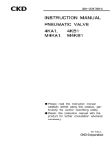
7) Bracket operation method
(1) Fix the bracket before using it. Insert the product at an odd angle into the bracket and fit to
the hook during installation.
(2) To remove, incline the product slightly and disengage the hook on the single side.
(3) Fit the projection of the bracket into the groove of another bracket to use.
Hook
Product
Bracket
Direction of
installation
Hook
Bracket
Product
Direction of removal
Direction of
installation

[SM-302688-A/3]
―9
―
CHECK
3
USAGE
4
3. Pre-operation check (post-fabrication check)
3.1 Appearance check
1) Check that the valve is fixed at the piping or mounting hole, while pushing by hand.
2) Check that the screws are not loose.
3.2 Leak check
1) To supply compressed air after connecting pipes, do not supply at a
high pressure first.
Piping connection will be disconnected and the tube will jump,
causing accidents.
1) Apply leak detection liquid at joints of the piping with a brush to check for air leaks.
2) Repeat manual operation slowly to check for disconnected tubes, vibration, and noise.
4. Adequate usage
1) Be sure to operate within the specification scope of the product.
Do not use with fluids other than the compressed air or at
pressures or temperatures out of the specification scope.
Otherwise burst, disconnection of the tube and/or leakage will be
caused.
1) The operation angle of this product is 90. Do not turn beyond 90.
2) Remove drain periodically if drain accumulates in the air filter.
3) If the filter element of the air filter is stained in black, adhesion of tar is probable. Periodically
replace the filter element.
4) If the lubricator is used to lubricate, periodically supply lubricant to the lubricator.
Use turbine oil class 1, ISO VG32 (no additive).
Open
Closed
!
CAUTION:
!
WARNING:

[SM-302688-A/3] ―10―
DISASSEMBLY
5
MAINTENANCE
6
DISPOSAL
7
5. Disassembly
1) Do not disassemble this product.
If failure is found, replace with a new one.
6. Maintenance
6.1 Maintenance and inspection
1) To use the product in the best condition, perform periodical inspection every year for regular
operation.
2) For details of inspection, refer to Section 3 “Pre-Operation Check.”
6.2 Maintenance parts
1) Do not disassemble this product. Replace the product if leakage, adhesion at the valve or other
faults is found during operation.
2) The approximate replacement timing is 10,000 operation cycles.
3) During operation at lower frequencies, replace at least every five years under consideration for
aging and deterioration of seal and packing.
7. Disposal
1) The material used for this product is metal, plastics and synthetic rubber.
Do not burn the product; take appropriate measures as an industrial waste.

[SM-302688-A/3]
―11―
INTERNAL
STRUCTURE
8
INTERNAL
STRUCTURE
ACTION
9
ACTION
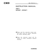
8. Internal structure and parts list
9. Description of action
2-port valve (2QV Series)
<Closed state> <Open state>
3-port valve (3QV Series)
<Closed state> <Open state>
Polyethersulfone

[SM-302688-A/3] ―12―
MODEL NUMBER/
S
PECIFICATION
10
10. Specifications of product
10.1 Model number
Quick valve
(a) (b)
(a) Model name (b) Port size (P port) - (A port) Special
bracket *
Symbol
Valve type Inlet side - Outlet side
2QV 2-port valve
04 - 04 Push in joint 4 - Push in joint 4
2QV - P1 3QV 3-port valve
06 - 06 Push in joint 6 - Push in joint 6
08S - 08S Push in joint 8 - Push in joint 8
08 - 08 Push in joint 8 - Push in joint 8
2QV - P2
10 - 10 Push in joint 10 - Push in joint 10
12 - 12 Push in joint 12 - Push in joint 12
6A - 04 R1/8 - Push in joint 4
2QV - P1
6A - 06 R1/8 - Push in joint 6
8A - 06 R1/4 - Push in joint 6
8A - 08S R1/4 - Push in joint 8
10A - 08 R3/8 - Push in joint 8
2QV - P2
10A - 10 R3/8 - Push in joint 10
15A - 10 R1/2 - Push in joint 10
15A - 12 R1/2 - Push in joint 12
04 - 6A Push in joint 4 - R1/8
2QV - P1
06 - 6A Push in joint 6 - R1/8
06 - 8A Push in joint 6 - R1/4
08S - 8A Push in joint 8 - R1/4
08 - 10A Push in joint 8 - R3/8
2QV - P2
10 - 10A Push in joint 10 - R3/8
10 - 15A Push in joint 10 - R1/2
12 - 15A Push in joint 12 - R1/2
6A - 6A R1/8 - R1/8 2QV - P1
8A - 8A R1/4 - R1/4
10A - 10A R3/8 - R3/8 2QV - P2
15A - 15A R1/2 - R1/2
* The bracket is common for the two- and three-port valves.
* Varies according to the body size. Be careful.
10.2 Specifications of product
Model number
Item
2QV/3QV
Working fluid Air
Max. working pressure MPa
1.0
Min. working pressure kPa
-100 (Note 1)
Proof pressure MPa
1.5
Fluid temperature ℃
0 to 60
Ambient temperature ℃
0 to 60
Changeover angle °
90
Tube Soft nylon tube (Tube F-15xx)
Urethane tube (Tube U-95xx, NU-xx)
Note 1: Use the insert ring when using the valve with the urethane tube (U-95xx, NU-xx) in a vacuum.
Note 2: We cannot meet requirements for oil proof treatment specification because lubricant is used.
2QV
04-04
/