Page is loading ...

Combination: C 0 Series
(excluding Oil Mist Filter)
Filter Regulator:
W 000, W 100 Series
Air Filter: F 000 Series
Regulator: R 000, R 100 Series
Lubricator: L 000 Series
INSTRUCTION MANUAL
• Read this Instruction Manual before using the product.
• Read the safety notes carefully.
• Keep this Instruction Manual in a safe and convenient place for future reference.
F.R.L. Unit
Modular Type
S
ELEX
F.R.L
.
Series
SM-189671-A/9

SM-189671-A/9 PREFACE
i 2020-06-19
PREFACE
Thank you for purchasing CKD's "Modular Type SELEX F.R.L. Series" F.R.L. unit.
This Instruction Manual contains basic matters such as installation and usage instructions in order to
ensure optimal performance of the product. Please read this Instruction Manual thoroughly and use the
product properly.
Keep this Instruction Manual in a safe place and be careful not to lose it.
Product specifications and appearances presented in this Instruction Manual are subject to change
without notice.
• The product is intended for users who have basic knowledge about materials, piping, electricity, and
mechanisms of pneumatic components. CKD shall not be responsible for accidents caused by
persons who selected or used the product without knowledge or sufficient training.
• Since there are a wide variety of customer applications, it is impossible for CKD to be aware of all of
them. Depending on the application or usage, the product may not be able to exercise its full
performance or an accident may occur due to fluid, piping, or other conditions. It is the responsibility
of the customer to check the product specifications and decide how the product shall be used in
accordance with the application and usage.

SM-189671-A/9 SAFETY INFORMATION
ii 2020-06-19
SAFETY INFORMATION
When designing and manufacturing any device incorporating the product, the manufacturer has an
obligation to ensure that the device is safe. To that end, make sure that the safety of the machine
mechanism of the device, the pneumatic or water control circuit, and the electric system that controls
such mechanism is ensured.
To ensure the safety of device design and control, observe organization standards, relevant laws and
regulations, which include the following:
ISO 4414, JIS B 8370, JFPS 2008 (the latest edition of each standard), the High Pressure Gas Safety
Act, the Industrial Safety and Health Act, other safety rules, organization standards, relevant laws and
regulations
In order to use our products safely, it is important to select, use, handle, and maintain the products
properly.
Observe the warnings and precautions described in this Instruction Manual to ensure device safety.
Although various safety measures have been adopted in the product, customer's improper handling may
lead to an accident. To avoid this:
Thoroughly read and understand this Instruction Manual
before using the product.
To explicitly indicate the severity and likelihood of a potential harm or damage, precautions are classified
into three categories: "DANGER", "WARNING", and "CAUTION".
DANGER Indicates an imminent hazard. Improper handling will cause death or serious
injury to people.
WARNING Indicates a potential hazard. Improper handling may cause death or serious
injury to people.
CAUTION Indicates a potential hazard. Improper handling may cause injury to people or
damage to property.
Precautions classified as "CAUTION" may still lead to serious results depending on the situation.
All precautions are equally important and must be observed.
Other general precautions and tips on using the product are indicated by the following icon.
Indicates general precautions and tips on using the product.

SM-189671-A/9 SAFETY INFORMATION
iii 2020-06-19
Precautions on Product Use
WARNING
The product must be handled by a qualified person who has extensive knowledge and
experience.
The product is designed and manufactured as a device or part for general industrial machinery.
Use the product within the specifications.
The product must not be used beyond its specifications. Also, the product must not be modified
and additional work on the product must not be performed.
The product is intended for use in devices or parts for general industrial machinery. It is not
intended for use outdoors or in the conditions or environment listed below.
• In applications for nuclear power, railroad system, aviation, ship, vehicle, medical equipment,
and equipment that directly touches beverage or food.
• For special applications that require safety including amusement equipment, emergency
shut-off circuit, press machine, brake circuit, and safety measures.
• For applications where life or properties may be adversely affected and special safety measures
are required.
(Exception is made if the customer consults with CKD prior to use and understands the
specifications of the product. However, even in that case, safety measures must be taken to avoid
danger in case of a possible failure.)
Do not handle the product or remove pipes and devices until confirming safety.
• Inspect and service the machine and devices after confirming the safety of the entire system.
Also, turn off the energy source (air supply or water supply) and power to the relevant facility.
Release compressed air and fluid from the system and use extreme care to avoid water or
electric leakage.
• Since there may be hot or live parts even after operation has stopped, use extreme care when
handling the product or removing pipes and devices.
• When starting or restarting a machine or device that incorporates pneumatic components, make
sure that a safety measure (such as a pop-out prevention mechanism) is in place and system
safety is secured.

SM-189671-A/9 CONTENTS
iv 2020-06-19
CONTENTS
PREFACE ........................................................................................................................... i
SAFETY INFORMATION .................................................................................................. ii
Precautions on Product Use .......................................................................................... iii
CONTENTS ...................................................................................................................... iv
1. INSTALLATION ......................................................................................................... 1
1.1 Environment ........................................................................................................ 1
1.2 Unpacking ........................................................................................................... 3
1.3 Mounting ............................................................................................................. 3
1.4 Piping .................................................................................................................. 5
2. USAGE ....................................................................................................................... 8
2.1 Operation .......................................................................................................... 10
3. MAINTENANCE AND INSPECTION ....................................................................... 12
3.1 Daily Inspection ................................................................................................. 13
3.2 Periodic Inspection............................................................................................ 13
3.3 How to Discharge Drainage .............................................................................. 14
3.4 How to Perform Maintenance ........................................................................... 14
4. TROUBLESHOOTING............................................................................................. 16
4.1 Problems, Causes, and Solutions .................................................................... 16
5. WARRANTY PROVISIONS ..................................................................................... 17
5.1 Warranty Conditions ......................................................................................... 17
5.2 Warranty Period ................................................................................................ 17

SM-189671-A/9 1. INSTALLATION
1 2020-06-19
1. INSTALLATION
1.1 Environment
WARNING
Do not use the product in an atmosphere where synthetic oil, organic solvent, chemicals,
cutting oil, screw lock agent, leak detection agent, hot water, or other hazardous factors are
present or in a place where they may adhere to the product.
Deterioration may occur since plastic bowls in the air filter and in the lubricator, the drip window of
the lubricator, and the pressure gauge lens are made of polycarbonate.
Avoid using the product if compressed air contains chemicals, in an atmosphere where
chemicals are present, or in a place where chemicals may adhere.
When used in the above environment, the plastic bowl may become damaged and this may lead to
accidents.
If the above environment cannot be avoided, use the optional metal bowl.
For more information about the chemical resistance of the plastic bowl, refer to the table "Chemical
resistance of plastic".
Install safety equipment if an output pressure above the set pressure of the regulator can
cause damage or operation fault on the secondary side device.
Use a reverse regulator equipped with a check valve when lowering both the primary side
pressure and the secondary side pressure to the atmospheric pressure at the same time.
Lowering the primary side pressure of a regulator not equipped with a check valve to the
atmospheric pressure will not lower the secondary side pressure.
Observe the conditions of use.
• There are cases in which the regulator cannot be used in secondary side sealing circuits and
balance circuits.
• Do not use the lubricator for lubricating air motors and bearings.
• The lubricator may not lubricate when used in machines that are operated with high frequency
such as
in
a press mach
ine.
CAUTION
Observe the following precautions regarding the ambient environment.
• Do not use the product where there is direct irradiation of ultraviolet rays.
• Avoid installing the product where it is exposed to direct sunlight.
• Avoid installing the product where it is subject to vibrations and shocks.
Install an air dryer and a drain separator before the air filter if there is a large amount of
drainage.
An excessive amount of drainage from the compressor may cause the air to become hot and
highly humid and this may lead to lower durability or corrosion of the product.
Make sure that substances such as chlorine do not become mixed with the compressed air
when using a water lubricated type compressor circuit.
Note that using
dry air
accelerates
the
deterioration of the
rubber parts
of
the regulator
.

SM-189671-A/9 1. INSTALLATION
2 2020-06-19
Do not use the product in an environment where:
• Ambient temperature is outside the range of 5°C to 60°C
• Air can freeze
• Water drop or cutting oil can splash onto the product
• Condensation may occur due to high humidity and temperature change
• Sea breeze or seawater can splash onto the product
• Atmosphere contains corrosive gas, fluids, or chemicals
• Atmosphere contains a lot of dust
• Atmosphere contains spatter
• It is exposed to direct sunlight, rain, wind, or water
• There is a heat source in the surrounding area and heat is radiated
• Ozone is produced
Chemical resistance of plastic
Type of
chemicals
Classification
Major chemical products Example of general use
Poly-
carbonate
bowl
Nylon
bowl
Nylon
body
Inorganic
chemicals
Acid Hydrochloric acid, sulfuric acid,
hydrofluoric acid, phosphoric acid,
and
chromic acid
Pickling solution for metal, acidic
degreasing solution, and film
treatment solution
N N N
Alkali Alkaline substances such as caustic
soda, caustic potash, slaked lime,
ammonia water, and sodium
carbonate
Alkaline degreasing solution for
metal, water-soluble cutting oil
agent, and leak detection agent N Y Y
Inorganic salt Sodium sulfide, sodium nitrate,
potassium dichromate, and sodium
sulfate
N Y Y
Organic
chemicals
Aromatic
hydrocarbon
Benzene, toluene, xylene,
ethylbenzene
,
and
styrene
Included in paint thinner (benzene,
toluene,
and
xylene)
N N N
Chlorinated
aliphatic
hydrocarbon
Methyl chloride, ethylene chloride,
methylene chloride, acetylene
chloride, chloroform, trichlene,
berklene,
and
carbon tetrachloride
Organic solvent cleaning solution
for metal (trichlene, berklene,
carbon tetrachloride, etc.) N Y Y
Chlorinated
aromatic
hydrocarbon
Chloro-benzene, dichloro-benzene,
and benzene hexachloride (B, H, C)
Agricultural chemicals
N Y Y
Petroleum
composition
Solvent naphtha, gasoline, and
kerosene
N Y Y
Alcohol Methyl alcohol, ethyl alcohol,
cyclohexanol,
and
benzyl alcohol
Anti-freezing agent and leak
detection agent
N N N
Phenol Carbolic acid, cresol, and naphthol Antiseptic solution N N N
Ether Methyl ether, ethyl methyl ether, and
ethyl ether
Additive for brake oil N Y Y
Ketone Acetone, methyl ethyl ketone,
C
yclohexanone
,
and
acetophenone
N N N
Carboxylic acid
Formic acid, acetic acid, butyric acid,
acrylic acid, oxalic acid, and phthalic
acid
Stain, aluminum treatment agent
(oxalic acid), base material for paint
(phthalic acid), and leak detection
agent
N N N
Ester Dimethyl phthalate (DMP), diethyl
phthalate (DEP), dibutyl phthalate
(DBP),
and
dioctyl phthalate (DOP)
Additive for lubrication oil, synthetic
oil, and rust preventive oil
P
lasticizer
for synthetic resins
N Y Y
Hydroxy acid Glycolic acid, lactic acid, malic acid,
citric acid,
and
tartaric acid
N N N
Nitro compound Nitromethane, nitroethane,
nitroethylene
,
and
nitrobenzene
N Y Y
Amine Methylamine, dimethylamine,
ethylamine, aniline
,
and
acetanilide
Additive for brake oil N N N
Nitrile Acetonitrile, acrylonitrile,
benzonitrile
,
and
acetisonitrile
Raw material for nitrile rubber N Y Y
Y: Resistant; N: Not resistant (Plastic will break.)

SM-189671-A/9 1. INSTALLATION
3 2020-06-19
1.2 Unpacking
Do not open the packing of the product until just before piping.
Foreign matters may enter the product and cause a f
ailure
or
malfunction.
• Check that the model number ordered and the model number indicated on the product are the same.
• Check the exterior of the product for any damage.
1.3 Mounting
C-type bracket (if selected in the model number)
Attach the C-type bracket to the product as shown in the figure below before piping.
Panel mounting of the regulator (excluding 8000-W Series)
When the panel mounting nut is loosened, the nut acts as a jack and the knob can be removed easily.
Secure with the nut when attaching the knob on the panel or attaching an L-type bracket.
Attach the nut before attaching the knob. (For R2000-W, the nut can be removed without
removing the knob.)
Align the convex portion of the C-type bracket
with the concave portion of the product and
push in.
Knob
Nut
SM-189671-A/9 1. INSTALLATION
4 2020-06-19
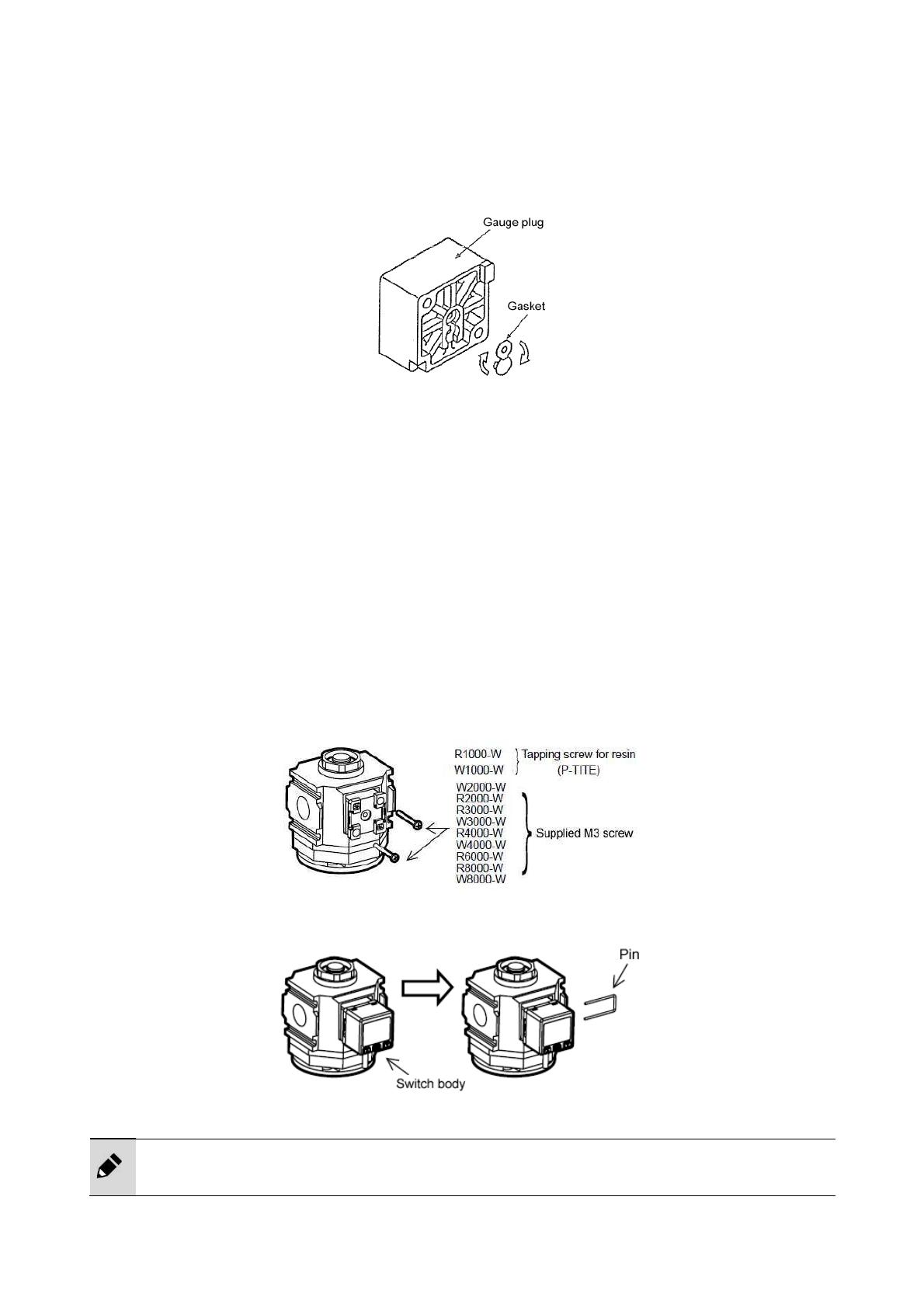
Regulator and filter regulator
• Lightly tighten (with 0.6 N·m or less) the mounting screws for embedded pressure gauges G401-0P
and G401 and the gauge plug.
• When mounting a pressure gauge onto a model without a pressure gauge (option T), remove the
gauge plug and attach the gasket on the rear side upside down.
• When mounting the pressure gauge with a safety mark or a general screw-in pressure gauge onto the
gauge plug, tighten it with a torque of 10 N·m to 15 N·m or less.
• Do not move or swing the product by holding the pressure adjustment knob on the regulator.
• Do not apply pressure exceeding the full-scale pressure specified for the pressure gauge. The
pressure gauge may become damaged. (Use extreme care when using a pressure gauge with a
full-scale pressure of 0.2 MPa or 0.4 MPa.)
Pressure switch (PPR)
1 Make sure your hands are clean.
Attach the O-rings to the two O-ring grooves on the adaptor.
2 Mount the adaptor to the regulator body using the two M3 screws supplied.
Be careful with the mounting position and direction so that the O-ring does not come off.
Do not fully tighten each screw at once. Tighten two screws alternately so that they are tightened
equally.
(Tightening torque: 0.5 N·m ± 0.1 N·m)
3 Mount the switch body and insert the supplied pin from the side of the adaptor.
• Insert the pin all the way in.
•
Check that the pin is
inserted
properly
before pressurizing.

SM-189671-A/9 1. INSTALLATION
5 2020-06-19
1.4 Piping
Do not apply pipe loads or torque to the body and the pipes.
Do not support the product at only one end as illustrated in the figure below since this may apply
excessive force and lead to damage.
<Piping load torque>
Series 1000-W 2000-W 3000-W 4000-W 6000-W 8000-W
Max. torque
(N·m) 15 15 50 50 100 100
For the 1000-W Series in particular, applying 30 N·m or more torque may cause damage to the
pipes.
Tighten the pipes with the specified tightening torque, including when the piping adaptors are
used
.
Fully flush and clean the pipes before use.
Residual dust or foreign matter in a pipe may cause operation fault.
Connect the pipes correctly according to the direction of flow by checking the direction of the
arrow.
Prevent foreign matters from entering the pipes while piping and connecting the fitting.
Be careful not to allow cutting chips from the piping screw and seal material from entering the
pipes while piping and connecting the fitting.
Residual dust or foreign matter in a pipe may cause lower performance of the product.
Tighten the pipes with the appropriate tightening torque.
Do not subject the body and the pipes to a bending moment that is due to pipe loads.
Follow the conditions below for the drain piping of the automatic drain.
To prevent operation faults, use pipes with an inside diameter of ø5.7 or more and a length of 5 m
or less for the section of pipes for discharging the drainage and avoid riser piping.
Avoid piping that applies lateral loads to the bowl. Secure the hexagon side of the cock and screw
the
fitting into the Rc1/4 internal thread.

SM-189671-A/9 1. INSTALLATION
6 2020-06-19
Pipe cleaning
Before piping, blow air into the pipes to clean the interior and to remove cutting chips and foreign
matters.
Seal material
Apply a seal tape or seal material to the screw threads leaving two or more threads at the pipe end
uncovered or uncoated. If the pipe end is fully covered or coated, a shred of seal tape or residue of seal
material may enter inside of the pipes or device and cause a failure.
When using a seal tape, wind it around the screw threads in the direction opposite from the screw
threads and press it down with your fingers to attach it firmly.
When using a liquid seal material, be careful not to apply it to resin parts. The resin parts can become
damaged and this may lead to a failure or malfunction.
Also, do not apply seal material to the internal threads.
Pipe screwing torque
Do not apply excessive torque to the body and the pipes when piping.
Series 1000-W 2000-W 3000-W 4000-W 6000-W 8000-W
Max. torque
(N·m) 15 30 30 30 70 70
Drain piping for plastic bowl
The plastic bowl has a barbed nipple connection for drain piping and the tube can be installed directly.
Check that the drain cock is closed before inserting the tube.
Avoid piping that applies lateral loads to the bowl.
Seal tape Seal material (solid or liquid)
C
orrect
C
orrect
I
ncorrect
I
ncorrect
Leave
two threads

SM-189671-A/9 1. INSTALLATION
7 2020-06-19
Drain piping for metal bowl with automatic drain
Secure the hexagon part of the cock and screw the fitting into the internal threads of the drain port.
Maximum tightening torque of the cock is 0.5 N·m.
When using a metal bowl with automatic drain, drainage cannot be manually discharged if a tightening
joint is used for the drain piping.
Piping of differential pressure detection ports
• For F6000- -W-Q and F8000- -W-Q
Differential pressure detection ports are available as an option for F6000-W and F8000-W Series.
By assembling the differential pressure gauge GA400-8-P02 to the differential pressure detection
ports, the degree of clogging in the filter element or oil mist filter mantle assembly can be visually
checked.
• For F6000- -W-QX1
When assembling the differential pressure gauge GA400-8-P02 to the differential pressure detection
ports, raise the gauge with piping material so that it does not interfere with piping.
Check the primary side (high pressure side) and the secondary side (low pressure side) port
positions and install the differential pressure gauge correctly.
F6000- -W-Q F8000- -W-Q
F6000- -W-Q1
Piping material

SM-189671-A/9 2. USAGE
8 2020-06-19
2. USAGE
Use the product within the specifications.
Do not use the product for medical purposes or in any equipment or circuit that concerns
human life.
Th
e
product is designed for industrial use.
Check the working circuit and the working fluid.
If fluids containing solids or fluids not in the specifications flow into the product, operation faults
may occur. Attach a filter to the primary side of the product to prevent solids from entering.
Set the secondary side pressure of the regulator to 85% or less of the primary side pressure.
The pressure drop may increase.
Do not use the OUT side as a closed circuit when using the regulators in parallel as shown
below.
If a closed circuit is required, attach a check valve to the OUT side of each regulator.
Do not use a distributor to divide air into lubricated air and non-lubricated air.
The lubricator oil may flow back.
If pulsation occurs on the regulator or the filter regulator, change the conditions of use or the
piping conditions. For example, lower the primary side pressure.
Pulsation may occur depending on the conditions of use or the piping conditions.
Check the minimum air rate for dripping required for the lubricator.
If the working air rate is low, oil may not drip.
Do not use the lubricator together with a compact pressure switch PPD and digital pressure
sensor PPX.
Since these switches do not have a drip-proof structure, operation may become disabled if oil
splashe
s
onto
the
switch
es
.

SM-189671-A/9 2. USAGE
9 2020-06-19
Conditions of use for the automatic drain
<NO type automatic drain (discharges drainage when pressure is not applied): "F" and
"FF">
• Use a compressor with a capacity of 0.75 kW {90 l/min (ANR)} or more.
• Set the pressure to 0.1 MPa or more. (Air is purged with initial drainage until pressure
reaches 0.1 MPa.)
<NC type automatic drain (does not discharge drainage when pressure is not applied):
"F1" and "FF1">
• Use a compressor (a compressor with a capacity of 0.75 kW or less can be used).
• Set the pressure to 0.15 MPa or more.
<1000 Series NC automatic drain>
• Set the flow rate to a value equal to or less than the maximum working flow rate.
• Avoid using the product where high vibrations occur, such as where the compressor is
directly installed, since air may leak from the drain port due to the vibration of the float.
• Avoid overflowing the drainage since operation faults may occur.
To use the product correctly:
• Check the primary side pressure and set the regulator pressure so that the pressure rises.
Lock the knob after setting.
• Check the arrow indicating the air inlet before connecting. Reverse connection may cause
a malfunction.
• Install the air filter and lubricator vertically with the case facing downward. Drainage may
not be properly discharged or checking the dripping of drainage may not be possible.
• Avoid using the automatic drain where vibrations occur since it may cause faults and
malfunctions.
When using the product for a large air blowing, it is recommended to install the product as
shown in the figure below so that the secondary side pressure can be measured more
accurately.
Adjusting the oil drip rate of lubricator
Use bare hands to turn the adjusting dome and adjust the oil drip rate. When turning the
dome in the closing direction, tighten with a torque of 0.5 N·m or less. The numbers (scale) on
the dial are used as a reference after adjustment and do not indicate the oil drip rate.
Oil drip rate
adjustment
Adjusting dome
Pressure gauge
D300-W or T-shaped piping

SM-189671-A/9 2. USAGE
10 2020-06-19
2.1 Operation
WARNING
Use Class 1 ISO VG32 turbine oil (additive-free) for the lubricator.
Other kinds of oil may cause damage to the product or operation faults.
Release the pressure completely from the bowl before removing the filling plug of the
lubricator.
To prevent the filling plug from popping out, loosen the filling plug by turning it by approximately 1
turn and release the pressure completely from the bowl before removing the filling plug.
Wipe
off
dust
s
around the fillin
g plug
to prevent
dusts
from scattering.
CAUTION
Pull the pressure adjustment knob to release the lock before setting the regulator pressure.
If the pressure is forcibly set without unlocking, the regulator may become damaged.
Adjust pressure in the direction of the pressure increase.
The correct pressure cannot be set if pressure is adjusted downward.
Exp1) In case of secondary pressure adjust to 0.6MPa from 0MPa
Turn the knob increase and adjust as 0.6MPa.
Exp2) In case of secondary pressure adjust to 0.5MPa from 0.6MPa
Turn the knob decrease and adjust to 0.5MPa on down,
turn the knob increase and adjust to 0.5MPa.
Supply oil to the lubricator bowl periodically so that it does not fall below the lower limit.
<Lubricating L1000-W>
Pressure in the bowl can be released by turning the filling plug. For operation, refer to "Removing
the filling plug (lubricator)". (Oil can be supplied while pipes are pressurized.)
Check that there is no pressure in the bowl, remove the bowl and bowl guard, and directly supply
oil to the bowl. For removing the bowl, refer to "3.4 How to Perform Maintenance".
< Lubricating L3000-W to L8000-W>
Slightly loosen the filling plug to release the pressure from the bowl and remove the filling plug. For
the filling plug, refer to "Removing the filling plug (lubricator)". (By removing the filling plug, oil can
be supplied while pipes are pressurized.)
Oil can be supplied from the filling plug hole after removing the plug. Also, it can be supplied to the
bowl directly by removing the bowl and bowl guard.
For removing the bowl, refer to "3.4 How to Perform Maintenance". For L8000, oil can be supplied
to the spacer from the fil
ling plug hole.

SM-189671-A/9 2. USAGE
11 2020-06-19
Adjusting the secondary side pressure (regulator and filter regulator)
• Pull up the pressure adjustment knob one notch to unlock it.
• To raise the secondary side pressure, turn the top of the knob in the H-direction, and to lower the
secondary side pressure, turn the knob in the L-direction.
• After setting the secondary side pressure, push down the adjustment knob one notch to lock it.
Adjusting the oil drip rate (lubricator)
To increase the drip rate, turn the adjusting dome in the O-direction, and to lower the drip rate, turn the
dome in the S-direction.
If the dome is hard to turn by hand, place a coin in the slit on the top of the dome and use it to turn the
dome.
Removing the filling plug (lubricator)
Do not forget to attach the filling plug after lubricating.
<L3000-W to L8000-W>
Do not remove the bowl without removing the filling plug (while the bowl is pressurized).
<L1000-W>
Pressure in the bowl is released by sliding the filling plug approximately 45° in the OPEN direction.
Do not remove the bowl with the filling plug in the SHUT direction (while the bowl is pressurized).
Pressure adjust
ment
knob
Adjusting
dome
Filling plug
Filling plug
OPEN
SHUT

SM-189671-A/9 3. MAINTENANCE AND INSPECTION
12 2020-06-19
3. MAINTENANCE AND INSPECTION
Stop supplying the pressure and make sure that there is no residual pressure before
maintenance.
Perform periodic inspections at least once every six months to detect cracks, scratches, and
other deteriorations on the plastic bowl in the air filter and in the lubricator.
Cracks, scratches, or other deteriorations may cause damage. Replace the bowl with a new plastic
bowl or a metal bowl.
Check for dirt on the plastic bowl in the air filter and in the lubricator and on the drip window
of the lubricator periodically.
If the bowl or the drip window is dirty, replace or clean the bowl or the window.
When cleaning, remove dirt using a diluted household detergent and then rinse well with clean
water to prevent damage to the product.
Discharge drainage from the air filter so that it does not accumulate beyond the upper limit.
If drainage flows into the secondary side, operation faults may occur in the device.
For plastic bowls, make sure that drainage does not accumulate over the "MAX. LEVEL" mark on
the bowl guard.
Before removing the bowl assembly, stop supplying the compressed air, release the pressure
from
the bowl
,
and
check
that there is no residual pres
sure in the bowl.
Thoroughly read and understand the Instruction Manual supplied with the product before use
and maintenance.
Check the oil drip rate of the lubricator once a day.
If the oil is not dripping properly, problems may occur with the component being lubricated.
Inspect and replace the filter element periodically.
Performance degradation may occur if the element is clogged.
Do not disassemble or modify the product.
For a model with differential pressure indicators, replace the element before all the
differential pressure indicators become red
.
Upper limit of drainage
Upper limit of
drainage
Metal bowl Metal bowl (flame-resistant, M1 type)

SM-189671-A/9 3. MAINTENANCE AND INSPECTION
13 2020-06-19
3.1 Daily Inspection
• Thoroughly read and understand this Instruction Manual before maintenance and inspection.
• Check that the product operates properly before starting use.
3.2 Periodic Inspection
• In order to use the product under optimum conditions, perform a periodic inspection every six months.
• It is recommended to check that there is no leakage from the pipes.

SM-189671-A/9 3. MAINTENANCE AND INSPECTION
14 2020-06-19
3.3 How to Discharge Drainage
Discharging drainage (filter and filter regulator)
Plastic bowl To discharge drainage, turn the cock in the O-direction, and to stop discharging, turn the cock in the
S-direction.
For the bowl with automatic drain, drainage is discharged automatically when it is accumulated or can be
discharged manually.
Maximum tightening torque of the plastic bowl drain cock is as follows.
1000 Series: 0.1 N·m
Others: 0.5 N·m
Metal bowl with
automatic drain
Drainage is discharged automatically when it is accumulated or can be discharged manually.
It is operated in the same way as the plastic bowl.
Drainage cannot be manually discharged if a tightening joint is used for the drain piping.
Maximum tightening torque of the cock is 0.5 N·m.
Manual discharge
metal bowl
To discharge drainage, turn the cock in the O-direction, and to stop discharging, turn the cock in the
S-direction.
3.4 How to Perform Maintenance
Removing the plastic bowl
<2000-W, 2500-W, 3000-W, 4000-W, 6000-W, and 8000-W Series>
<1000-W Series>
Latch
(Push and turn.)
Latch
(Push and turn
.
)
Latch
(Push and turn.)

SM-189671-A/9 3. MAINTENANCE AND INSPECTION
15 2020-06-19
Removing the metal bowl
<2000-W, 3000-W, 4000-W, 6000-W, and 8000-W Series>
Element of W1000-W to W8000-W
Since the valve assembly can also be removed during maintenance, inspect all parts of the assembly at
the same time.
Be careful not to lose any part.
Lubricator
Supply oil to the lubricator bowl periodically so that the amount of oil does not fall below the lower limit.
See the figure below for the oil lower limit.
Plastic bowl Metal bowl (excluding 1000 Series)
* The oil lower limit is indicated on the bowl guard as "MIN. LEVEL".
Spring
Element
Louver
Oil lower limit
Oil lower limit
Latch
(Push and turn.)
/


