Page is loading ...

SM-272367-A/9
INSTRUCTION MANUAL
BLOCK MANIFOLD
MN3E MN4E SERIES
Please read this instruction manual carefully
before using this product, particularly the
section describing safety
Retain this instruction manual with the
product for further consultation whenever
necessary

[SM-272367-A/9]
-
1
-
For Safety Use
To use this product safety, basic knowledge of pneumatic equipment, including
materials, piping, electrical system and mechanism, is required (ISO 4414 *1,
JIS B 8370 *2).
We do not bear any responsibility for accidents caused by any person without
such knowledge or arising from improper operation.
Our customers use this product for a very wide range of applications, and we
cannot keep track of all of them. Depending on operating conditions, the
product may fail to operate to maximum performance, or cause an accident.
Thus, before placing an order, examine whether the product meets your
application, requirements, and how to use it.
This product incorporates many functions and mechanisms to ensure safety.
However, improper operation could result in an accident. To prevent such
accidents,
read this operation manual carefully for proper
operation.
Observe the cautions on handling described in this manual, as well as the
following instructions:
Failure to pay attention to DANGER notices may cause a
situation that results in a fatality or serious injury and that
requires urgent addressing.
Failure to pay attention to WARNING notices may result in a
fatality or serious injury.
Failure to pay attention to WARNING notices may result in
injury or damage to equipment or facilities.
*1) ISO 4414 : Pneumatic fluid power Recommendations for the application of
equipment to transmission and control systems.
*2) JIS B 8370 : General rule for pneumatic systems
WARNING
CAUTION :
DANGER :

[SM-272367-A/9]
-
2
-
UNPACKING (Chapter 3.)
Bags containing solenoid valves should be opened only when you
are ready to connect the valves to the pipes immediately afterward.
If bags are opened before the valves are ready to be connected
to the pipes, the entry of foreign matter from the piping ports
could cause the solenoid valves to fail or malfunction.
INSTALLATION (Chapter 4.)
If you have to use the product under conditions that are different
from the specified conditions or if you intend to use the product for
a special application, be sure to consult us about the product
specifications before using the product.
ENVIRONMENT (Section 4.1)
a) In a dusty environment, foreign matter may enter even through the exhaust port.
The movement of the exhaust valve causes a respiratory action at the exhaust valve,
which may cause inhalation of foreign matter near the exhaust port. This potential
situation would be worse if the exhaust port is facing upward. Attach a silencer to the
exhaust port or have the exhaust port face downward.
b) Keep the solenoid valve system dry. Take care to avoid direct contact with dripping water or
splashes of cutting oil.
If the solenoid valve system is wet by a direct contact with water or cutting oil, an electrical
leak or burnt solenoid coils may result. Protect the solenoid valve system by using a cover
or by installing it inside a paneled casing. If the cylinder rod is splashed with cutting oil, the
oil may penetrate through the cylinder into the secondary side piping of the solenoid valve.
This must be prevented to avoid malfunctions. Consult us for preventive measures.
c) The coils will produce heat.
Particularly if the solenoid valve system is installed in a control board or if the solenoid
coils need to be energized for a long time, consider providing sufficient ventilation to
release the heat. The coils can get very hot.
d) Do not use the solenoid valve system in an atmosphere that includes a corrosive gas or
solvent vapors.
Do not use the solenoid valve system in an atmosphere that includes a corrosive gas such
as the sulfur dioxide gas or in an atmosphere that includes solvent vapors.
e) Vibrations and shocks
Do not subject the solenoid valve system to vibrations 50m/s
2
or stronger or shocks
300m/s
2
or stronger.
f) Avoid using the solenoid valve system in a humid environment because the humidity is
likely to cause condensation with a change in the temperature.
g) Do not use the normal type solenoid valves for an application that requires conformity with
explosion-proof specifications. Choose explosion-proof solenoid valves instead.
h) The packing and gaskets may deteriorate sooner than usual if used in an atmosphere with
a higher than normal density of ozone (for example, the atmosphere near a beach or in an
area with frequent thunderstorms).
Consult us for the packing and gaskets to be used in an atmosphere with a higher ozone
density.
CAUTION :
CAUTION :
CAUTION :

[SM-272367-A/9]
-
3
-
INSTALLATION (Section 4.2)
When installing a solenoid valve unit, never attempt to hold it in
position by means of the pipes connected to it.
Mount the solenoid valve by applying the mounting screws
and/or mounting plate to the solenoid valve.
If you choose to mount the solenoid valve manifold on a DIN rail,
make sure that the DIN rail is strong enough.
PIPING (Section 4.3)
a) Observe the recommended tightening torque when connecting
pipes.
Observing the recommended tightening torque prevents air
leakage and damage to the screw threads. To prevent damage
to the screw threads, first use your hand to lightly tighten the
screw and then use a tool to tighten the screw to the
recommended torque.
b) Make sure that the pipes will not be disconnected at the joints
by mechanical movements, vibrations or tension.
If the exhaust piping of the pneumatic circuit is disconnected,
the actuator speed control is disabled.
If the above happens to a chuck holding mechanism, the chuck
will open. The inadvertent opening of the chuck may cause a
serious accident.
c) When supplying the compressed air for the first time after
completing the piping, be sure to check every joint in the piping
for air leakage.
d) When supplying the compressed air for the first time after
completing the piping, increase the air pressure gradually but
never introduce a highly-pressurized air suddenly.
A sudden introduction of a highly-pressurized air may
disconnect pipes at joints and/or cause the tubes to jump
around, any of which may cause an injury.
e) Do not decrease the inside diameter of the piping from any of
the solenoid valve exhaust ports to a diameter less than the
exhaust pipe connecting port size.
Normal operation of the actuator depends on the smoothness
of the exhaust flow. With a manifold system, a restriction to the
exhaust flow may prevent normal operation of other solenoid
valves.
f) Removal of foreign matter
Rust and other foreign matter in the pneumatic circuit may
cause a malfunction or leakage from the valve seat. Insert a
filter (maximum allowable particle size 5 m or less)
immediately upstream of the solenoid valve.
g) Air supply
Do not restrict the flow of air through the air supply piping. With
a manifold system with multiple stations, a drop in the air
supply pressure may cause trouble through a delay in the
operation timing.
WIRING (Section 4.4)
Before supplying the power, check the power supply voltage and
the current type (AC or DC).
CAUTION :
WARNING :
CAUTION :
CAUTION :

[SM-272367-A/9]
-
4
-
MANUAL OVERRIDE (Section 5.2)
a) After using the manual override, be sure to reset the manual
override to the original (OFF) position before resuming the
operation of the device.
After a operation, be sure to release the lock to turn the manual
override OFF.
With the 4E-Series solenoid valve system, the lock is released
(the manual override turned OFF) if the manual override
protection cover is closed.
b) Before using the manual override, make sure that nobody is
present near the cylinder to be activated.
AIR QUALITY (Section 5.3)
a) Do not supply anything other than compressed air.
b) Supply clean compressed air without any mixture of corrosive
gas.
a) Compressed air usually contains a large amount of drain,
oxidized oil, tar, foreign matter, and rust from the piping. Filter
out those elements in the supplied air because they may cause
a malfunction and decrease service life. In addition, clean the
exhaust before it is released to the air to minimize pollution.
b) Once you have lubricated a pre-lubricated valve, the valve is no
longer capable of running without being lubricated from the
outside. Do not leave the valve without lubrication but keep it
lubricated.
c) Do not use spindle oil or machine oil. They may induce
expansion of the rubber parts, which may cause a malfunction.
ELECTRIC CIRCUITS (Section 5.4)
a) Check for the presence of any current leak from the external
control device because it may cause an erroneous valve
operation.
When a programmable controller or a similar control device is
used, a current leak may prevent the normal returning of the
valve when the solenoid is de-energized.
b) Restriction on current leak
When controlling solenoid valves using a programmable
controller or a similar control device, make sure that the current
leak in the programmable controller output is equal to or less
than the level shown in the table below. A current leak larger
than the allowable level may cause an erroneous valve
operation.
WARNING :
CAUTION :
WARNING
CAUTION :
12
V
DC
1.5 mA or lower
24V
DC
1.8 mA or lower
CR circuit
Solenoid valve
Contact
C
R
Programma-
ble
controller

[SM-272367-A/9]
-
5
-
a) The surge suppressor limits the surge voltage generating from
the solenoid valve, which reaches several hundred volts, to a
low voltage level bearable for output contacts. This function
may be insufficient for some output circuits and the voltage may
cause breakage or malfunction. Check the surge voltage
limitation level of the solenoid valve in your circuit, the dielectric
voltage and circuit configuration of the output devices and the
delay for recovery to check for serviceability. If necessary, install
another measures against surges. The 4E Series solenoid
valves equipped with a surge suppressor suppress the
terminal-to-terminal reverse voltage surge generating upon
shutoff, to the level shown in the table below.
b) If the output unit is of an NPN type, the output transistor is
susceptible to the sum of the voltage specified in the table
above and the source voltage. Install a contact protection
circuit.
PERIODIC INSPECTION (Section 6.1)
Before providing a maintenance service, cut the power and the
supply of compressed air and confirm the absence of residual
pressure.
The above is required to ensure safety.
Regularly perform the daily and periodic inspections to correctly
maintain product performance.
If the product is not correctly maintained , product performance
may deteriorate dramatically, resulting in a shorter service life,
fractures of components, and malfunctions.
CAUTION :
WARNING :
CAUTION :
In case of 12VDC About 27V
In case of 24VDC About 47V
Solenoid valve side
Programmable
controller side
<Example 1 of output transistor protection circuit>
<Example 2 of output transistor protection circuit>
Solenoid valve side
Programmable
controller side

[SM-272367-A/9]
-
6
-
INDEX
Block Manifold
MN3E MN4E Series
Manual No. SM-272367-A
1. PRODUCT ------------------------------------------------------------------------- 7
2. INTERNATIONAL SYSTEM OF UNITS (SI)
AND PORT INDICATION
2.1 Port Indication ------------------------------------------------------------ 10
2.2 Conversion between International System
of Units (SI) and Conventional Units -------------------------------- 10
3. UNPACKING -------------------------------------------------------------------- 11
4. INSTALLATION
4.1 Environment --------------------------------------------------------------- 12
4.2 Installation ----------------------------------------------------------------- 13
4.3 Piping ----------------------------------------------------------------------- 14
4.4 Wiring ----------------------------------------------------------------------- 19
5. OPERATING RECOMMENDATION
5.1 Operation ------------------------------------------------------------------ 46
5.2 Manual Override --------------------------------------------------------- 51
5.3 Air Quality ------------------------------------------------------------------ 53
5.4 Electric circuits------------------------------------------------------------ 55
6. MAINTENANCE
6.1 Periodic Inspection ------------------------------------------------------ 58
6.2 Disassembling and Reassembling ----------------------------------- 59
7. TROUBLESHOOTING -------------------------------------------------------- 63
8. PRODUCT SPECIFICATIONS AND HOW TO ORDER
8.1 Product Specifications -------------------------------------------------- 64
8.2 How to Order -------------------------------------------------------------- 67
Created 2002.04.22
Revised 2013.09.30

[SM-272367-A/9]
-
7
-
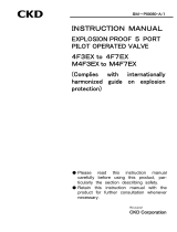
PRODUCT
1. PRODUCT
Valve block
Fixing screw
There are two fixing screw for wiring blocks and end blocks, securing the entire manifold to
the DIN rail.
Wiring block
The block has a built-in printed circuit board.
Mounting (DIN) rail
End retainer
It is temporarily fixed to the wiring block and the end block.
Connecting key
The key should be flat with other blocks in after the connection of the block and the end
block.
End block
Located opposite the wiring block, the end block secures the entire manifold to the DIN rail. It
has a function of common supply/exhaust flow plugging.
Electric component cover
The electricity indicator lamp comes on inside the white frame when the solenoid is
energized. The “a” solenoid and the “b” solenoid are red and green, respectively, when they
are lighted.
Manual override
The protection cover prevents accidental operation of the manual override.
The user must open the cover before operating the manual override.
Supply/exhaust block
Regulator block.
Dummy block.
Joint
The joint is a replaceable cartridge push-in type.
Valve block
Fixing screw
Wiring block
Mounting (DIN) rail
End retainer
Connecting key
End block
Electric component cover
Manual override
Supply/exhaust block
Joint
Regulator block
Dummy block

[SM-272367-A/9]
-
8
-
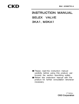
PRODUCT
D sub-connector type (T30/T30R) Flat cable type (T5*/T5*R)
Intermediate wiring block, RITS connector
type (TM1*)
Intermediate wiring block, flat cable type
(TM52)
D-sub 25-pin connector
Control terminals of the manifold solenoid valve are integrated.
Fixing screw
The screw is used to secure the connectors
Power indicator lamp
The lamp comes on when the power is on with the correct polarity.
Flat cable connector
A common connector for the control terminals of the manifold electromagnetic valve.
Power terminal stand (only T50 type)
The stand is used when it is necessary to obtain power from outside.
RITS connector
Control terminals of the manifold solenoid valve are integrated.
* For details of manifold configuration, refer to page 64 and the following pages.

[SM-272367-A/9]
-
9
-
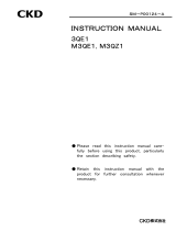
PRODUCT
Individual wiring type
Power supply socket ass'y
The power supply socket supplies individual power to the valve. The internal circuit of the
individual wiring valve block is completely isolated from the reduced wiring electric circuit
inside the manifold. Therefore insertion of an individual wiring valve block between reduced
wiring valve blocks does not cause a change in the pin layout of the wiring block related to
the reduced wiring valve block.
* Individual inputs from a separate system can be added independently of integral wiring of the
reduced wiring system.
Type with built-in individual power supply (AUX) function
Electric cover AUX
The cover is equipped with an individual power supply terminal.
Power supply socket ass'y
The socket supplies individual power to the valve. When the socket is inserted, the power
sent to the socket insertion valve from the reduced wiring system is cut off.
* The model with a built-in individual power supply (AUX) function is capable of individual control
of arbitrary valves with the separate power supply in the manifold having been connected with
a reduced wiring system. It is effective for adjustment of equipment.
Regulator block
The main pressure supplied by supply/exhaust block
can be decompressed.
The pressure directly supplied from the outside of manifold
can be decompressed. It can be used as main pressure.
Dummy block
These are mounted when later addition of valves is
planned, etc.

[SM-272367-A/9]
-
10
-
SI UNIT
2. INTERNATIONAL SYSTEM OF UNITS (SI) AND PORT INDICATION
2.1 Port Indication
Each piping port is marked with ISO and JIS conformable piping port indication codes like 1P
and 4A.
Application ISO JIS
Supply port 1 P
Output port 4 A
Output port 2 B
Exhaust port 5 R1
Exhaust port 3 R2
2.2 Conversion between International System of Units (SI) and Conventional Units
In this manual, values are expressed using the International System of Units (SI).
Use the table below to convert them into values expressed in conventional units.
Table of conversion between SI units and conventional units
(The values printed in Bolds fonts are values given in the International System of Units (SI)):
Force
N dyn kgf
1 1 10
5
1.01972 10
-1
1 10
-5
1 1.01972 10
-6
9.80665 9.80665 10
5
1
Stress
Pa or N/m
2
Mpa or N/mm
2
kgf/mm
2
kgf/cm
2
1 1 10
-6
1.01972 10
-7
1.01972 10
-5
1 10
6
1 1.01972 10
-1
1.01972 10
9.80665 10
6
9.80665 1 1 10
2
9.80665 10
4
9.80665 10
-2
1 10
-2
1
Note: 1Pa=1N/m
2
, 1MPa=1N/mm
2
Pressure
Pa kPa MPa bar kgf/cm
2
atm mmH2O mmHg Torr
1 1 10
-3
1 10
-6
1 10
-5
1.01972 10
-5
9.86923 10
-6
1.01972 10
-1
7.50062 10
-3
1 10
3
1 1 10
-3
1 10
-2
1.01972 10
-2
9.86923 10
-3
1.01972 10
2
7.50062
1 10
6
1 10
3
1 1 10 1.01972 10 9.86923 1.01972 10
5
7.50062 10
3
1 10
5
1 10
2
1 10
-1
1 1.01972 9.86923 10
-1
1.01972 10
4
7.50062 10
2
9.80665 10
4
9.80665 10 9.80665 10
-2
9.80665 10
-1
1 9.67841 10
-1
1 10
4
7.35559 10
2
1.01325 10
5
1.01325 10
2
1.01325 10
-1
1.01325 1.01323 1 1.03323 10
4
7.60000 10
2
9.80665 9.80665 10
-3
9.80665 10
-6
9.80665 10
-5
1 10
-4
9.67841 10
-5
1 7.35559 10
-2
1.33322 10
2
1.33322 10
-1
1.33322 10
-4
1.33322 10
-3
1.35951 10
-3
1.31579 10
-3
1.35951 10 1
Note: 1Pa=1N/m
2
Example (converting a pressure value):
1kgf/cm
2
0.980665Mpa 1MPa
1.01972 10kgf/cm
2

[SM-272367-A/9]
-
11
-
UNPAC
K
ING
3. UNPACKING
Bags containing solenoid valves should be opened only when you
are ready to connect the valves to the pipes immediately afterward.
If bags are opened before the valves are ready to be connected
to the pipes, the entry of foreign matter from the piping ports
could cause the solenoid valves to fail or malfunction.
a) Check the model number imprinted on the product to make sure that the product you received is
exactly the product you ordered.
b) Check the exterior of the product for any damage.
c) Before using the product, read the supplied documentation.
CAUTION :

[SM-272367-A/9]
-
12
-
INSTALL
A
TION
4. INSTALLATION
If you have to use the product under conditions that are different
from the specified conditions or if you intend to use the product for
a special application, be sure to consult us about the product
specifications before using the product.
4.1 Environment
a) In a dusty environment, foreign matter may enter even through
the exhaust port.
The movement of the exhaust valve causes a respiratory action
at the exhaust valve, which may cause inhalation of foreign
matter near the exhaust port. This potential situation would be
worse if the exhaust port is facing upward. Attach a silencer to
the exhaust port or have the exhaust port face downward.
b) Keep the solenoid valve system dry. Take care to avoid direct
contact with dripping water or splashes of cutting oil.
If the solenoid valve system is wet by a direct contact with
water or cutting oil, an electrical leak or burnt solenoid coils
may result. Protect the solenoid valve system by using a cover
or by installing it inside a paneled casing. If the cylinder rod is
splashed with cutting oil, the oil may penetrate through the
cylinder into the secondary side piping of the solenoid valve.
This must be prevented to avoid malfunctions. Consult us for
preventive measures.
c) The coils will produce heat.
Particularly if the solenoid valve system is installed in a control
board or if the solenoid coils need to be energized for a long
time, consider providing sufficient ventilation to release the
heat. The coils can get very hot.
d) Do not use the solenoid valve system in an atmosphere that
includes a corrosive gas or solvent vapors.
Do not use the solenoid valve system in an atmosphere that
includes a corrosive gas such as the sulfur dioxide gas or in an
atmosphere that includes solvent vapors.
e) Vibrations and shocks
Do not subject the solenoid valve system to vibrations 50m/s
2
or stronger or shocks 300m/s
2
or stronger.
f) Avoid using the solenoid valve system in a humid environment
because the humidity is likely to cause condensation with a
change in the temperature.
g) Do not use the normal type solenoid valves for an application
that requires conformity with explosion-proof specifications.
Choose explosion-proof solenoid valves instead.
h) The packing and gaskets may deteriorate sooner than usual if
used in an atmosphere with a higher than normal density of
ozone (for example, the atmosphere near a beach or in an area
with frequent thunderstorms).
Consult us for the packing and gaskets to be used in an
atmosphere with a higher ozone density.
WARNING :
CAUTION :

[SM-272367-A/9]
-
13
-
INSTALL
A
TION
4.2 Installation
When installing a solenoid valve unit, never attempt to hold it in
position by means of the pipes connected to it.
Mount the solenoid valve by applying the mounting screws
and/or mounting plate to the solenoid valve.
If you choose to mount the solenoid valve manifold on a DIN rail,
make sure that the DIN rail is strong enough.
4.2.1 A work space for installation, removal, wiring, and piping operations should be provided
around the installed solenoid valve system.
4.2.2 Installation using
Note, however, that if the system is not properly mounted to the DIN rail it may fall and break
the manifold. If the manifold is to be used in an environment where it can be subjected to
vibrations and shocks, secure the DIN rail to the mounting surface by applying screws at
intervals of 50 mm, and check that it is securely mounted before using the manifold.
Installation using a DIN rail
MN4E Series
Set the jaw of the retainer on the
DIN rail.
While holding down the retainer
to eliminate the gap between
blocks, press the retainer toward
the direction of arrow.
Tighten the DIN rail set screw.
Tightening torque:
1.4 0.2N m
CAUTION :
WARNING :
Set the jaw of the valve
block on the DIN rail.
Retainer
1.4N m

[SM-272367-A/9]
-
14
-
INSTALL
A
TION
4.3 Piping
a) Observe the recommended tightening torque when connecting
pipes.
Observing the recommended tightening torque prevents air
leakage and damage to the screw threads. To prevent damage
to the screw threads, first use your hand to lightly tighten the
screw and then use a tool to tighten the screw to the
recommended torque.
b) Make sure that the pipes will not be disconnected at the joints
by mechanical movements, vibrations or tension.
If the exhaust piping of the pneumatic circuit is disconnected,
the actuator speed control is disabled.
If the above happens to a chuck holding mechanism, the chuck
will open. The inadvertent opening of the chuck may cause a
serious accident.
c) When supplying the compressed air for the first time after
completing the piping, be sure to check every joint in the piping
for air leakage.
d) When supplying the compressed air for the first time after
completing the piping, increase the air pressure gradually but
never introduce a highly-pressurized air suddenly.
A sudden introduction of a highly-pressurized air may
disconnect pipes at joints and/or cause the tubes to jump
around, any of which may cause an injury.
e) Do not decrease the inside diameter of the piping from any of
the solenoid valve exhaust ports to a diameter less than the
exhaust pipe connecting port size.
Normal operation of the actuator depends on the smoothness
of the exhaust flow. With a manifold system, a restriction to the
exhaust flow may prevent normal operation of other solenoid
valves.
f) Removal of foreign matter
Rust and other foreign matter in the pneumatic circuit may
cause a malfunction or leakage from the valve seat. Insert a
filter (maximum allowable particle size 5 m or less)
immediately upstream of the solenoid valve.
g) Air supply
Do not restrict the flow of air through the air supply piping. With
a manifold system with multiple stations, a drop in the air
supply pressure may cause trouble through a delay in the
operation timing.
Tightening torque
Joint screw Tightening torque N m
M3 0.3 to 0.6
M5 1.0 to 1.5
Rc1/8 3 to 5
CAUTION :

[SM-272367-A/9]
-
15
-
INSTALL
A
TION
4.3.1 Seal material
When using seal material, take care to avoid getting it in the pipes or overflowing on the
exterior surface of the pipes.
When applying fluororesin sealing tape to the screw threads, wind the tape two or three
times around the threads but leave the one or two threads at the pipe end uncovered. Firmly
press the tape against the threads using the tip of your fingernail. When applying liquid type
seal material, apply the material to all the threads except one or two threads at the pipe end
and take care not to apply too much of it.
Never apply the seal material to the female threads in the device side piping port.
4.3.2 Flushing
Before connecting pipes, flush the interiors of the tubes, solenoid valves, and connected
devices to remove foreign matter.
4.3.3 M3 M5 joint
M3 and M5 joints are sealed using a gasket (Model No. for the gasket only: FGS). Do not
retighten the joint screw when pressure is generated in the pneumatic circuit. Design and
construct the piping system in such a way that the valves may be removed and reinstalled if
a trouble should happen.
4.3.4 Blow circuit
Do not open the cylinder port circuit to the air because a drop in the air supply pressure may
cause a malfunction. Select the external pilot type design instead of the internal pilot type
design. The lowest allowable pressure with the internal pilot type design is 0.2 MPa.
4.3.5 Exhaust port
Minimize the restriction to the flow of the exhaust air because such restriction may cause a
delay in the cylinder response. If such a delay happens, the speed needs to be adjusted
between the cylinder and solenoid valve.
(Correct) (Incorrect)
Seal Tape Sealant (Paste or liquid)
(Correct) (Incorrect)
Solid liquid
sealant
Solid liquid
sealant

[SM-272367-A/9]
-
16
-
INSTALL
A
TION
4.3.6 Pipe connections
(1) Tubes to be used
For use with solenoid valves with one-touch joints, select tubes of the type specified by us:
Soft nylon tubes (F-1500 Series)
Urethane tubes (U-9500 Series)
* • For Ø1.8 barbed (CF), use an UP-9102 (urethane).
• For Ø1.8 push in joints (C18), use an UP-9402 (urethane).
(2) For installation at a site that has spatters in the air, select incombustible tubes or metal pipes.
(3) For a piping used for both hydraulic and pneumatic controls, select a hydraulic hose.
When combining a spiral tube with a standard one-touch joint, fix the tube origin using a hose
band. Otherwise the rotation of the tube will decrease the efficiency of the clamping.
For use in a high-temperature atmosphere, select fastener joints instead of one-touch joints.
(4) When selecting from tubes commercially available, carefully study the accuracy of the outside
diameter as well as the wall thickness and the hardness. The hardness of an urethane tube
should be 93 C or more (as measured by a rubber hardness meter).
With a tube that does not have a sufficient accuracy of the outside diameter or the specified
hardness, a decrease in the chucking force may cause disconnection or difficulty in inserting.
Tube dimensions
Outside diameter
mm
Inside diameter mm
Nylon Urethane
1.8 - 1.2
3 - 2
4 2.5 2
6 4 4
8 5.7 5
10 7.2 6.5
(5) Minimum bending radius of tubes
Observe the minimum bending radius of tubes. Neglecting the minimum bending radius may
cause disconnection or leaks.
Tube bore Minimum bending radius mm
Nylon Urethane
1.8 - 4
3 - 8
4 10 10
6 20 20
8 30 30
10 40 40
(6) Cutting a tube
To cut a tube, use a tube cutter to cut the tube perpendicularly to the length of the tube. Inserting
an obliquely cut end of a tube may cause air leakage.
Outside diameter allowance
Soft or hard nylon 0.1mm
Urethane 1.8, 3 0.1mm
Urethane 4, 6 +0.1mm
-0.15mm
Urethane 8, 10 +0.1mm
-0.2mm

[SM-272367-A/9]
-
17
-
INSTALL
A
TION
(7) Tube connections
Do not bend a tube immediately at where it is connected to the joint but lead it out straight from
the end of the joint for a length equal to or greater than the outside diameter of the tube. The
tension applied sideways through the tube should not exceed 40N (about 5N for CF, C18, CL18
and CLL18).
(8) Blank plug to be used
For use with a solenoid valve with a one-touch joint, select the blank plug specified by us:
Blank plug (PG-P2-B) : Ø1.8 push in joint
(N4E00-JOINT-PP3MW): Ø3 push in joint
(GWP -B Series) : Ø4 to 8 push in joint
(9) Operating method of Ø1.8 barbed (CF).
Insert Air Fiber properly while
checking visually.
Insert the collar until it stops.
Cut the tip of Air Fiber perpendic-
ularly.
Pull the collar to lock Air Fiber.
Insert Air Fiber until it stops.

[SM-272367-A/9]
-
18
-
INSTALL
A
TION
4.3.7 External pilot (K) type piping port
A different type supply port will be provided for the external pilot (K) type air supply. Since a
6mm diameter push-in joint is used for the pilot air supply, be sure to connect the piping
correctly. Erroneous piping can cause a malfunction.
Port indication :
Application Indication (ISO conformable)
Pilot air Supply port 12/14
Be careful of the supply pressure when you use Two 3 -port valves built-in type.
As for Two 3 -port valves built-in type , valves work by the main P pressure.
Be careful that main(P)pressure doesn't become more than pilot PA pressure.
Be careful that main(P)pressure doesn't become less than 0.2MPa.
External pilot air supply
port is push in joint
on the supply/exhaust block

[SM-272367-A/9]
-
19
-
INSTALL
A
TION
4.4 Wiring
Before supplying the power, check the power supply voltage and
the current type (AC or DC).
4.4.1 D sub-connector type : The connector for the T30/T30R
1) T30/T30R connector
The connector for the T30/T30R, which is usually called the D sub-connector, is widely used
in FA and OA equipment. The 25P type, in particular, is the connector specified in the
RS232C standard for use in personal computer communication.
The manifold station number is 1 ,2, 3, ..., starting at the wiring block. Note that the
numbering direction of T30 is different from that of T30R.
2) Cautions regarding the connector type (T30/T30R)
(1) It is necessary to match the signal arrangement of the PC output unit and that on the valve side.
(2) The operation power is DC24V or DC12V.
(3) Voltage drops will occur depending on cable lengths or at the time of simultaneous power supply.
Make sure that a voltage drop for the solenoid is within 10% of the rated voltage.
(4) In case of a valve block equipped with a built-in individual power supply (AUX) function or a
built-in low heat generation and power saving circuit, the conducting polarity is positive common
only.
Internal circuit
Manifold station
number 1st station 2nd station nth station
CAUTION
:
3rd station nth station 3rd station 2nd station 1st station
/