Page is loading ...

EME149A-20
BL A C K B OX
®
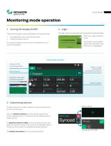
Use this intelligent environmental monitoring
device to identify problems before they disrupt
your equipment.
Features an embedded Web server and Linux operating system.
ServSensor V4E Lite with 20 or 60 VAC or VDC Dry Contacts
EME149A-20
EME149A-60
EME149D-20
EME149D-60
Order toll-free in the U.S.: Call 877-877-BBOX (outside U.S. call 724-746-5500) •
FREE technical support 24 hours a day, 7 days a week: Call 724-746-5500 or fax 724-746-0746 •
Mailing address: Black Box Corporation, 1000 Park Drive, Lawrence, PA 15055-1018 •
Web site: www.blackbox.com • E-mail: info@blackbox.com
Customer
Support
Information

724-746-5500 | blackbox.com
Page 2
EME149A-20
724-746-5500 | blackbox.com
Trademarks Used in this Manual
We‘re here to help! If you have any questions about your application
or our products, contact Black Box Tech Support at 724-746-5500
or go to blackbox.com and click on “Talk to Black Box.”
You’ll be live with one of our technical experts in less than 30 seconds.
Trademarks Used in this Manual
Black Box and the Double Diamond logo are registered trademarks of BB Technologies, Inc.
Bluetooth is a registered trademark of Bluetooth Sig, Inc.
Unicenter is a registered trademark of Computer Associates Think, Inc.
SiteScope is a registered trademark of Freshwater Software, Inc.
HP and OpenView are registered trademarks of Hewlett-Packard Company.
IBM and Tivoli are registered trademarks of International Business Machines Corporation.
WhatsUp is a registered trademark of Ipswitch, Inc.
Linux is a registered trademark of Linus Torvalds.
MS-DOS is a registered trademark of Microsoft Corporation.
Denika and WebNM are registered trademarks of Plixer International, Inc.
Big Brother is a registered trademark of Quest Software, Inc.
MRTG is a registered trademark of Rand Investments, Inc.
Modbus is a registered trademark of Schneider Automation, Inc.
Somix is a registered trademark of Somix Technologies, Inc.
Any other trademarks mentioned in this manual are acknowledged to be the property of the trademark owners.

724-746-5500 | blackbox.com
724-746-5500 | blackbox.com
Page 3
EME149A-20
FCC and IC RFI Statements
Federal Communications Commission and Industry Canada Radio Frequency Interference
Statements
This equipment generates, uses, and can radiate radio-frequency energy, and if not installed and used properly, that is, in strict
accordance with the manufacturer’s instructions, may cause inter ference to radio communication. It has been tested and found to
comply with the limits for a Class A computing device in accordance with the specifications in Subpart B of Part 15 of FCC rules,
which are designed to provide reasonable protection against such interference when the equipment is operated in a commercial
environment. Operation of this equipment in a residential area is likely to cause interference, in which case the user at his own
expense will be required to take whatever measures may be necessary to correct the interference.
Changes or modifications not expressly approved by the party responsible for compliance could void the user’s authority to
operate the equipment.
This digital apparatus does not exceed the Class A limits for radio noise emis sion from digital apparatus set out in the Radio
Interference Regulation of Industry Canada.
Le présent appareil numérique n’émet pas de bruits radioélectriques dépassant les limites applicables aux appareils numériques de
la classe A prescrites dans le Règlement sur le brouillage radioélectrique publié par Industrie Canada.

724-746-5500 | blackbox.com
Page 4
EME149A-20
724-746-5500 | blackbox.com
NOM Statement
Instrucciones de Seguridad
(Normas Oficiales Mexicanas Electrical Safety Statement)
1. Todas las instrucciones de seguridad y operación deberán ser leídas antes de que el aparato eléctrico sea operado.
2. Las instrucciones de seguridad y operación deberán ser guardadas para referencia futura.
3. Todas las advertencias en el aparato eléctrico y en sus instrucciones de operación deben ser respetadas.
4. Todas las instrucciones de operación y uso deben ser seguidas.
5. El aparato eléctrico no deberá ser usado cerca del agua—por ejemplo, cerca de la tina de baño, lavabo, sótano mojado o cerca
de una alberca, etc.
6. El aparato eléctrico debe ser usado únicamente con carritos o pedestales que sean recomendados por el fabricante.
7. El aparato eléctrico debe ser montado a la pared o al techo sólo como sea recomendado por el fabricante.
8. Servicio—El usuario no debe intentar dar servicio al equipo eléctrico más allá a lo descrito en las instrucciones de operación.
Todo otro servicio deberá ser referido a personal de servicio calificado.
9. El aparato eléctrico debe ser situado de tal manera que su posición no interfiera su uso. La colocación del aparato eléctrico
sobre una cama, sofá, alfombra o superficie similar puede bloquea la ventilación, no se debe colocar en libreros o gabinetes
que impidan el flujo de aire por los orificios de ventilación.
10. El equipo eléctrico deber ser situado fuera del alcance de fuentes de calor como radiadores, registros de calor, estufas u otros
aparatos (incluyendo amplificadores) que producen calor.
11. El aparato eléctrico deberá ser connectado a una fuente de poder sólo del tipo descrito en el instructivo de operación, o como
se indique en el aparato.
12. Precaución debe ser tomada de tal manera que la tierra fisica y la polarización del equipo no sea eliminada.
13. Los cables de la fuente de poder deben ser guiados de tal manera que no sean pisados ni pellizcados por objetos colocados
sobre o contra ellos, poniendo particular atención a los contactos y receptáculos donde salen del aparato.
14. El equipo eléctrico debe ser limpiado únicamente de acuerdo a las recomendaciones del fabricante.
15. En caso de existir, una antena externa deberá ser localizada lejos de las lineas de energia.
16. El cable de corriente deberá ser desconectado del cuando el equipo no sea usado por un largo periodo de tiempo.
17. Cuidado debe ser tomado de tal manera que objectos liquidos no sean derramados sobre la cubierta u orificios de ventilación.
18. Servicio por personal calificado deberá ser provisto cuando:
A: El cable de poder o el contacto ha sido dañado; u
B: Objectos han caído o líquido ha sido derramado dentro del aparato; o
C: El aparato ha sido expuesto a la lluvia; o
D: El aparato parece no operar normalmente o muestra un cambio en su desempeño; o
E: El aparato ha sido tirado o su cubierta ha sido dañada.

724-746-5500 | blackbox.com
724-746-5500 | blackbox.com
Page 5
EME149A-20
Table of Contents
Table of Contents
1. Specifications .......................................................................................................................................................................................... 6
2. Overview ............................................................................................................................................................................................ 7
2.1 Introduction .................................................................................................................................................................................... 7
2.2 What‘s Included .............................................................................................................................................................................. 7
2.3 Hardware Description ..................................................................................................................................................................... 8
2.3.1 EME149A-20 Front Panel ...................................................................................................................................................... 8
2.3.2 EME149A-20 Back Panel ....................................................................................................................................................... 9
2.3.3 EME149A-60 Front Panel .....................................................................................................................................................10
2.3.4 EME149A-60 Back Panel .....................................................................................................................................................11
2.3.5 EME149D-20 Front Panel .....................................................................................................................................................12
2.3.6 EME149D-20 Back Panel ......................................................................................................................................................13
2.3.7 EME149D-60 Front Panel.....................................................................................................................................................14
2.3.8 EME149D-60 Back Panel .....................................................................................................................................................15
2.4 ServSensor with 20 or 60 Extra Dry Contact Inputs, VAC, or VDC ..................................................................................................16
2.4.1 Extra Dry Contact Input Practical Applications .....................................................................................................................16
2.4.2 ServSensor with 20 or 60 Extra Dry Contact Web Interface Setup .......................................................................................17
3. Installation .......................................................................................................................................................................................... 20
3.1 Setting the IP Address ................................................................................................................................................................... 20
3.2 Testing the New IP Address with the “Ping” Command ................................................................................................................ 22
3.3 Firmware Upgrade ........................................................................................................................................................................ 23
3.4 Multiusers and Groups Setup ........................................................................................................................................................ 25
3.4.1 Group Setup....................................................................................................................................................................... 25
3.4.2 User Setup ......................................................................................................................................................................... 28
3.5 Services and Security .................................................................................................................................................................... 30
3.5.1 Active Services Application (Disabling)................................................................................................................................ 30
3.5.2 Closing or Changing Ports Disabling HTTP and Enabling HTTPS .......................................................................................... 31
3.5.3 The SNMPv3 SSL Security Feature ....................................................................................................................................... 32
3.5.4 Active Security ................................................................................................................................................................... 33
3.5.5 The NAC or Network Access Control Security Feature ........................................................................................................ 34
3.6 Setting Up a Sensor ...................................................................................................................................................................... 34
3.6.1 Notification Thresholds ....................................................................................................................................................... 36
3.6.2 Advanced Sensor Settings .................................................................................................................................................. 38
3.7 Using an Internal Mic as a Sound Detection Sensor ....................................................................................................................... 46
3.8 Expansion Ports ............................................................................................................................................................................ 49
4. Notifications .......................................................................................................................................................................................... 52
4.1 Adding a Notification .................................................................................................................................................................... 52
4.2 SNMP Trap .................................................................................................................................................................................... 53
4.3 E-mail .......................................................................................................................................................................................... 57
4.4 SMS Notification ........................................................................................................................................................................... 62
5. Mapping .......................................................................................................................................................................................... 68
5.1 Adding a Map .............................................................................................................................................................................. 68
5.2 Monitoring via the Map Interface .................................................................................................................................................. 72
6. Filters .......................................................................................................................................................................................... 73
6.1 Sensor Filters ................................................................................................................................................................................ 73
6.2 Syslog Filters ..................................................................................................................................................................................74
7. Making the ServSensor Visible to the Internet ....................................................................................................................................... 77
8. Frequently Asked Questions (FAQs) ....................................................................................................................................................... 78

724-746-5500 | blackbox.com
Page 6
EME149A-20
724-746-5500 | blackbox.com
Chapter 1: Specifications
1. Specifications
Audio — Sampling rate: 8 kHz
Certifications — AdRem NetCrunch, Quest Software–Big Brother
®
, Castle Rock, HP
®
OpenView
®
, IBM
®
Tivoli
®
, LoriotPro,
Logalot, MRTG
®
, SiteScope
®
, Somix
®
—WebNM
®
and Denika
®
, WhatsUp
®
Gold, Computer Associates Unicenter
®
TNG
Components — Manufactured using highly integrated, low-power surface-mount technology to ensure long-term reliability;
MX25 processor, 128 MB nano flash; internal on-board memory slot
Configuration — Via Web browser (HTTP/HTTPS)
Expandable Modules — EME1X8: 8-port intelligent sensors module;
EME1DC16: 16-port dry-contacts modules
Mean Time Between Failures (MTBF) — 400,000 hours
Memory — 28 MB nano flash
Network Interface — (1) 10/100BASE-T Ethernet RJ-45
Operating System — Embedded Linux
Processor — IM X25 CPU
Protocols Supported (Client) — DHCP, DNS, SMTP, (5) NTP, SNMP
Connectors — Inputs: (8) RJ-45 for connecting sensors; (4) RJ-45 expansion ports; (1) USB Version 1.1 Type A; (1) 2.5" jack
for analog audio; (1) RS-485 2-pin terminal box (used for Modbus
®
);
Dry contacts: EME149A-20, EME149D-20: (20);
EME149A-60, EME149D-60: (60)
Output: (1) 2.5" jack for analog audio; (1) 2.5" jack for microphone
Indicators — EME149A-20, EME149D-20: (42) LEDs: (1) Power LED, (1) Link LED, (40) LEDs (Status and Online)
for (20) dry contacts;
EME149D-20, EME149D-60: (122) LEDs: (1) Power LED, (1) Link LED, (120) LEDs (Status and Online) for (60) dry contacts
Temperature Tolerance — Operating: 32 to 131° F (0 to +55° C)
Humidity — 20 to 80%, noncondensing
Power — Input: 100–240 VAC, 47-63 Hz external power supply;
Output: 7.0–9 VDC, 3 amps;
Consumption: 6.15 watts, 0.82 amps
Size — EME149A-20, EME149D-20: 1.8"H x 17.08"W x 5.4"D (4.6 x 43.4 x 13.7 cm);
EME149A-60, EME149D-60: 5"H x 18"W x 3.45"D (12.7 x 45.7 x 8.7 cm)
Weight — EME149A-20, EME149D-20: 5.73 lb. (2.6 kg);
EME149A-60, EME149D-60: 6.83 lb. (3.1 kg)

724-746-5500 | blackbox.com
724-746-5500 | blackbox.com
Page 7
EME149A-20
Chapter 2: Overview
2. Overview
2.1 Introduction
Used for environmental monitoring, the ServSensor V4E Lite identifies problems before they lead to business disruptions. This
high-speed, accurate, intelligent monitoring device features a completely embedded host and Linux
®
operating system.
2.2 What’s Included
Your package should contain the following items. If anything is missing or damaged, contact Black Box Technical Support at
724-746-5500.
• (1) ServSensor V4E Lite with 20 or 60 Dry Contacts VAC or VDC
• (1) 5-ft. crossover cable
• (2) rackmounting brackets with screws
• (1) power adapter
• (1) power cord
• (21) or (61) 2-wire terminal blocks (installed)
• (1) CD-ROM containing this user’s manual and Help files

724-746-5500 | blackbox.com
Page 8
EME149A-20
724-746-5500 | blackbox.com
Chapter 2: Overview
2.3 Hardware Description
Figures 2-1 through 2-8 illustrate the ServSensors’ front and back panels. Tables 2-1 through 2-8 describe their components.
2.3.1 EME149A-20 Front Panel
1
2
5
7
8
3
4
6
Figure 2-1. Front panel.
Table 2-1. Front-panel components.
Number Component Description
1 Power LED When the unit is powered on, the power LED will be lit continuously. If the
power LED is flashing, there is a problem with the CPU. Contact Technical
Support at 724-746-5500 or info@blackbox.com.
2 Link LED The Link LED indicates network connectivity. It lights when a network is
connected to the ServSensor V4E Lite.
3 Mic The mic is a small hole for access to the internal microphone. Use it as a
sound sensor (or use an external mic).
4 SD memory card slot Place your SD card in the removable SD memory card slot. It can store sounds
recorded from the internal microphone and also the current firmware of the
unit.
5 Activity LED The Activity LED flashes when network traffic is sent to or received by the
ServSensor V4E Lite.
6 Status/Online LEDs 1–8 The Status/Online LEDs are numbered 1–8. They indicate the connectivity
status of the sensors connected to each port. You can also use these LEDs to
indicate system status during various operations.
Additionally, the LEDs can indicate the progress of an upgrade. The red LEDs
move from left to right to indicate activity, and all the green LEDs indicate
overall progress of the upgrade. When all the red lights are off and the green
are on, the upgrade/recovery process is complete.
These lights also indicate if the unit is operating in safe mode. This is when
the unit loads the operating system (OS) with a minimal set of drivers. If your
device enters safe mode after rebooting, contact Black Box Technical Support
at 724-746-5500 or info@blackbox.com.
The unit may enter recovery mode if a firmware upgrade is incomplete. In this
case, the unit displays a continuously lit row of red LEDs. If this happens,
contact Black Box Technical Support at 724-746-5500 or info@blackbox.com.

724-746-5500 | blackbox.com
724-746-5500 | blackbox.com
Page 9
EME149A-20
Chapter 2: Overview
Table 2-1 (Continued). Front panel components.
Number Component Description
7 Expansion ports E1–E4 Use the four expansion ports numbered E1–E4 to connect the 8-port
expansion module (EME1X8) and/or the 16 dry-contact expansion module
(EME1DC16).
8 (40) LED indicators There are two LEDs (Status and Online) for each dry contact.
2.3.2 EME149A-20 Back Panel
Figure 2-2 shows the ServSensor’s back panel. Table 2-2 describes its components.
11 12 13 14 15 16 17
19 18 9 10
Figure 2-2. Back panel.
Table 2-2. Back panel components.
Number Component Description
9 (8) RJ-45 connectors Use these ports to connect Intelligent Sensors to the ServSensor V4E Lite.
10 Barrel connector This is a 7.5-VDC plug. Connect a 7.0–9.0-V, 2.5-A power supply (included).
11 Mic out connector Connect an external microphone for voice modem applications.
12 Audio in Connect an external microphone.
13 Audio out Connect the output for external speakers.
14 USB Type A port Use the USB 1.1 port to connect a USB GBarPRS/GSM compatible modem,
a USB Wi-Fi dongle, or a USB Bluetooth
®
dongle.
15 2-pin terminal block (RS-485 port) The ServSensor V4E Lite supports Modbus master or slave.
16 RJ-45 10/100 network port Use this RJ-45 port to connect your ServSensor V4E Lite to the network.
17 Reset Press this button to reset the ServSensor V4E Lite.
18 EXT GND Use the EXT. GND connector to externally ground the unit.
19 (20) dry contacts (20) VAC dry contacts

724-746-5500 | blackbox.com
Page 10
EME149A-20
Chapter 2: Overview
2.3.3 EME149A-60 Front Panel
1 2 6 7 8
3 4 8 8
5
Figure 2-3. EME149A-60 Front panel.
Table 2-3. Front-panel components.
Number Component Description
1 Power LED When the unit is powered on, the power LED will be lit continuously. If the
power LED is flashing, there is a problem with the CPU. Contact Technical
Support at 724-746-5500 or info@blackbox.com.
2 Link LED The Link LED indicates network connectivity. It lights when a network is
connected to the ServSensor V4E Lite.
3 Mic The mic is a small hole for access to the internal microphone. Use it as a
sound sensor (or use an external mic).
4 SD memory card slot Place your SD card in the removable SD memory card slot. It can store sounds
recorded from the internal microphone and also the current firmware of the
unit.
5 Activity LED The Activity LED flashes when network traffic is sent to or received by the
ServSensor V4E Lite.
6 Status/Online LEDs 1–8 The Status/Online LEDs are numbered 1–8. They indicate the connectivity
status of the sensors connected to each port. You can also use these LEDs to
indicate system status during various operations.
Additionally, the LEDs can indicate the progress of an upgrade. The red LEDs
move from left to right to indicate activity, and all the green LEDs indicate
overall progress of the upgrade. When all the red lights are off and the green
are on, the upgrade/recovery process is complete.
These lights also indicate if the unit is operating in safe mode. This is when
the unit loads the operating system (OS) with a minimal set of drivers. If your
device enters safe mode after rebooting, contact Black Box Technical Support
at 724-746-5500 or info@blackbox.com.
The unit may enter recovery mode if a firmware upgrade is incomplete. In this
case, the unit displays a continuously lit row of red LEDs. If this happens,
contact Black Box Technical Support at 724-746-5500 or info@blackbox.com.

724-746-5500 | blackbox.com
EME149A-20
Page 11
Chapter 2: Overview
Table 2-3 (Continued) . Front panel components.
Number Component Description
7 Expansion ports E1–E4 Use the four expansion ports numbered E1–E4 to connect the 8-port
expansion module (EME1X8) and/or the 16 dry-contact expansion module
(EME1DC16).
8 (120) LED indicators There are two LEDs (Status and Online) for each dry contact.
2.3.4 EME149A-60 Back Panel
Figure 2-4 shows the ServSensor’s back panel. Table 2-4 describes its components.
19 11 12 13 14
19 18 9 15 10
17
16
Figure 2-4. EME149A-60 back panel.
Table 2-4. Back panel components.
Number Component Description
8 (8) RJ-45 connectors Use these ports to connect Intelligent Sensors to the ServSensor V4E Lite.
9 Barrel connector This is a 7.5-VDC plug. Connect a 7.0–9.0-V, 2.5-A power supply (included).
10 Mic out connector Connect an external microphone for voice modem applications.
11 Audio in Connect an external microphone.
12 Audio out Connect the output for external speakers.
13 USB Type A port Use the USB 1.1 port to connect a USB GBarPRS/GSM compatible modem,
a USB Wi-Fi dongle, or a USB Bluetooth
®
dongle.
14 2-pin terminal block (RS-485 port) The ServSensor V4E Lite supports Modbus master or slave.
15 RJ-45 10/100 network port Use this RJ-45 port to connect your ServSensor V4E Lite to the network.
16 Reset Press this button to reset the ServSensor V4E Lite.
17 EXT GND Use the EXT. GND connector to externally ground the unit.
18 (60) dry contacts (60) VAC dry contacts

724-746-5500 | blackbox.com
Page 12
EME149A-20
Chapter 2: Overview
2.3.5 EME149D-20 Front Panel
1
2
5
7
8
3
4
6
Figure 2-5. Front panel.
Table 2-5. Front-panel components.
Number Component Description
1 Power LED When the unit is powered on, the power LED will be lit continuously. If the
power LED is flashing, there is a problem with the CPU. Contact Technical
Support at 724-746-5500 or info@blackbox.com.
2 Link LED The Link LED indicates network connectivity. It lights when a network is
connected to the ServSensor V4E Lite.
3 Mic The mic is a small hole for access to the internal microphone. Use it as a
sound sensor (or use an external mic).
4 SD memory card slot Place your SD card in the removable SD memory card slot. It can store sounds
recorded from the internal microphone and also the current firmware of the
unit.
5 Activity LED The Activity LED flashes when network traffic is sent to or received by the
ServSensor V4E Lite.
6 Status/Online LEDs 1–8 The Status/Online LEDs are numbered 1–8. They indicate the connectivity
status of the sensors connected to each port. You can also use these LEDs to
indicate system status during various operations.
Additionally, the LEDs can indicate the progress of an upgrade. The red LEDs
move from left to right to indicate activity, and all the green LEDs indicate
overall progress of the upgrade. When all the red lights are off and the green
are on, the upgrade/recovery process is complete.
These lights also indicate if the unit is operating in safe mode. This is when
the unit loads the operating system (OS) with a minimal set of drivers. If your
device enters safe mode after rebooting, contact Black Box Technical Support
at 724-746-5500 or info@blackbox.com.
The unit may enter recovery mode if a firmware upgrade is incomplete. In this
case, the unit displays a continuously lit row of red LEDs. If this happens,
contact Black Box Technical Support at 724-746-5500 or info@blackbox.com.

724-746-5500 | blackbox.com
Page 13
EME149A-20
Chapter 2: Overview
Table 2-5 (Continued). Front-panel components.
Number Component Description
7 Expansion ports E1–E4 Use the four expansion ports numbered E1–E4 to connect the 8-port
expansion module (EME1X8) and/or the 16 dry-contact expansion module
(EME1DC16).
8 (40) LED indicators There are two LEDs (Status and Online) for each dry contact.
2.3.6 EME149D-20 Back Panel
Figure 2-6 shows the ServSensor’s back panel. Table 2-6 describes its components.
20 10 11 12 13 14 15 16 17
19 18 9
Figure 2-6. EME149D-20 back panel.
Table 2-6. Back-panel components.
Number Component Description
9 (8) RJ-45 connectors Use these ports to connect Intelligent Sensors to the ServSensor V4E Lite.
10 Barrel connector This is a 7.5-VDC plug. Connect a 7.0–9.0-V, 2.5-A power supply (included).
11 Mic out connector Connect an external microphone for voice modem applications.
12 Audio in Connect an external microphone.
13 Audio out Connect the output for external speakers.
14 USB Type A port Use the USB 1.1 port to connect a USB GBarPRS/GSM compatible modem,
a USB Wi-Fi dongle, or a USB Bluetooth
®
dongle.
15 2-pin terminal block (RS-485 port) The ServSensor V4E Lite supports Modbus master or slave.
16 RJ-45 10/100 network port Use this RJ-45 port to connect your ServSensor V4E Lite to the network.
17 Reset Press this button to reset the ServSensor V4E Lite.
18 EXT GND Use the EXT. GND connector to externally ground the unit.
19 (20) dry contacts (20) VDC dry contacts
20 DC power connector 7.5 VDC power inputs

724-746-5500 | blackbox.com
Page 14
EME149A-20
Chapter 2: Overview
2.3.7 EME149D-60 Front Panel
1 2 6 7 8
3 4 8 8
5
Figure 2-7. Front panel.
Table 2-7. Front-panel components.
Number Component Description
1 Power LED When the unit is powered on, the power LED will be lit continuously. If the
power LED is flashing, there is a problem with the CPU. Contact Technical
Support at 724-746-5500 or info@blackbox.com.
2 Link LED The Link LED indicates network connectivity. It lights when a network is
connected to the ServSensor V4E Lite.
3 Mic The mic is a small hole for access to the internal microphone. Use it as a
sound sensor (or use an external mic).
4 SD memory card slot Place your SD card in the removable SD memory card slot. It can store sounds
recorded from the internal microphone and also the current firmware of the
unit.
5 Activity LED The Activity LED flashes when network traffic is sent to or received by the
ServSensor V4E Lite.
6 Status/Online LEDs 1–8 The Status/Online LEDs are numbered 1–8. They indicate the connectivity
status of the sensors connected to each port. You can also use these LEDs to
indicate system status during various operations.
Additionally, the LEDs can indicate the progress of an upgrade. The red LEDs
move from left to right to indicate activity, and all the green LEDs indicate
overall progress of the upgrade. When all the red lights are off and the green
are on, the upgrade/recovery process is complete.
These lights also indicate if the unit is operating in safe mode. This is when
the unit loads the operating system (OS) with a minimal set of drivers. If your
device enters safe mode after rebooting, contact Black Box Technical Support
at 724-746-5500 or info@blackbox.com.
The unit may enter recovery mode if a firmware upgrade is incomplete. In this
case, the unit displays a continuously lit row of red LEDs. If this happens,
contact Black Box Technical Support at 724-746-5500 or info@blackbox.com.

724-746-5500 | blackbox.com
EME149A-20
Page 15
Chapter 2: Overview
Table 2-7 (Continued). Front-panel components.
Number Component Description
7 Expansion ports E1–E4 Use the four expansion ports numbered E1–E4 to connect the 8-port
expansion module (EME1X8) and/or the 16 dry-contact expansion module
(EME1DC16).
8 (120) LED indicators There are two LEDs (Status and Online) for each dry contact.
2.3.8 EME149D-60 Back Panel
Figure 2-8 shows the ServSensor’s back panel. Table 2-8 describes its components.
20 10 11 12 13 14 15 16 17
19 18 9
Figure 2-8. EME149D-60 back panel.
Table 2-8. Back-panel components.
Number Component Description
9 (8) RJ-45 connectors Use these ports to connect Intelligent Sensors to the ServSensor V4E Lite.
10 Barrel connector This is a 7.5-VDC plug. Connect a 7.0–9.0-V, 2.5-A power supply (included).
11 Mic out connector Connect an external microphone for voice modem applications.
12 Audio in Connect an external microphone.
13 Audio out Connect the output for external speakers.
14 USB Type A port Use the USB 1.1 port to connect a USB GBarPRS/GSM compatible modem,
a USB Wi-Fi dongle, or a USB Bluetooth
®
dongle.
15 2-pin terminal block (RS-485 port) The ServSensor V4E Lite supports Modbus master or slave.
16 RJ-45 10/100 network port Use this RJ-45 port to connect your ServSensor V4E Lite to the network.
17 Reset Press this button to reset the ServSensor V4E Lite.
18 EXT GND Use the EXT. GND connector to externally ground the unit.
19 (60) dry contacts (60) VDC dry contacts
20 DC power connector DC power input

724-746-5500 | blackbox.com
Page 16
EME149A-20
724-746-5500 | blackbox.com
Chapter 2: Overview
2.4 ServSensor with 20 or 60 Extra Dry Contact Inputs, VAC, or VDC
The 20 or 60 extra dry contact inputs on the ServSensor can be configured as inputs only up to 5 Volts in normal operation. In
opto-isolation mode they can input up to 30 Volts DC. This will protect these inputs and the unit from high voltages and spikes.
Opto-isolators provide complete electrical separation between the ServSensor and the dry contact. The base units are therefore
protected against possible large voltage spikes caused by lightning, for example.
The figure below shows the jumpers (on the dry contact board) set up to provide opto-isolators support.
Refer to the rear panel of the ServSensor above for the other connections on the rear panel, as they are exactly the same in
functionality.
Figure 2-9. Jumper settings.
The OID for the extra dry contact inputs is:- .1.3.6.1.4.1.3854.1.2.2.1.18.1.3.<port>
2.4.1 Extra Dry Contact Input Practical Applications
The extra dry contact inputs can be used to monitor many types of equipment, for example, you can run the connection from
warning lights on alarm panels to the dry contact inputs, so that when the warning light on the alarm panel is activated, the dry
contact is triggered in the unit’s Web interface, thus allowing you to send notifications via emails or SNMP traps.

724-746-5500 | blackbox.com
724-746-5500 | blackbox.com
Page 17
EME149A-20
Chapter 2: Overview
2.4.2 ServSensor with 20 or 60 Extra Dry Contact Web Interface Setup
Figure 2-10. Sensors page.
First login to the ServSensor Web interface, then navigate to the Sensors Page, then click on the Dry Contact Ports link in the left
hand column. You can now click on the dry contact port to set up that port as shown in the screen shot above.
Figure 2-11. Normal settings screen.
In the Normal tab settings we can see that the sensor is currently offline, so to enable the dry contact port we would click on the
Offline button.

724-746-5500 | blackbox.com
Page 18
EME149A-20
724-746-5500 | blackbox.com
Chapter 2: Overview
Figure 2-12. Critical status screen.
We can see the dry contact input is now Critical and we can set how we require the Normal State to be as shown above—either
in the Closed GND or Open +5VDC. We can also rename our normal and critical state of the input.
Figure 2-13. Online selected.

724-746-5500 | blackbox.com
724-746-5500 | blackbox.com
Page 19
EME149A-20
Chapter 2: Overview
We can see that the dry contact input now is in the normal state as shown in the screen shot on the previous page.
Figure 2-14. Advanced settings screen.
If we click on the Advanced tab, we can set the graphing to “on,” set the sensor URL, set the Filter Status, and enable the
Calendar. (More on the Sensor URL and Filter Status in sections 3.6 and 6.1).

724-746-5500 | blackbox.com
Page 20
EME149A-20
724-746-5500 | blackbox.com
Chapter 3: Installation
3. Installation
3.1 Setting Up the IP Address
The ServSensor V4E Lite is shipped with the default IP address of 192.168.0.100. Follow the steps listed below to change this IP
address to fit your own network configuration.
Before starting, make sure you have these items:
• (1) RJ-45 male CAT5 crossover cable
• (1) PC with Ethernet card or LAN socket
• (1) Power socket for the unit to connect to
To set up the IP address:
1. Connect the ServSensor V4E Lite via its Ethernet port to your computer’s Ethernet port with a CAT5 crossover cable.
2. Open a Web browser and type the default IP address (as in Figure 3-1), then press the Enter key.
Figure 3-1. Google Web Browser screen.
NOTE: In some cases, your computer might not be able to connect to this default IP address. In this situation, you will need to
change the IP address of your PC. See the instructions above.
3. After you press the Enter key in Step 2, Figure 3-2 appears. The default password for Admin is “public.” Change the password
to make your unit secure.
/