Page is loading ...

From lab to production,
providing a window into the process
-1-
www.dynisco.com
Rev: n/aP/N: n/a ECO: n/a
Dynisco 1480 1/8 DIN Indicator
Concise Product Manual 59471-5
Operang Manual

From lab to production,
providing a window into the process
-2-
www.dynisco.com
Rev: n/aP/N: n/a ECO: n/a
CAUTION: Installaon should be only performed by technically competent
personnel. Local Regulaons regarding electrical installaon & safety must be
observed. The host equipment is required to provide a suitable electrical, mechanical
and re enclosure to meet relevant safety standards. Impairment of protecon will
occur if the product is used in a manner not specied by the manufacturer.
CAUTION: All power supply connecons to the device must be removed when
carrying out any form of maintenance.
1. Installaon
Installing Opon Modules/Maintenance
CPU PCB
Opon Module 2
Opon Module 1
Mounng Struts
Opon Module 3
PSU PCB
Future Opons
To access modules, rst detach the PSU and CPU boards from the front by liing rst the upper, and
then lower mounng struts. Gently separate the boards.
a. Plug the required opon modules into the correct connectors, as shown below.
b. Locate the module tongues in the corresponding slot on the opposite board.
c. Hold the main boards together while relocang back on the mounng struts.
Replace the instrument by aligning the CPU and PSU boards with their guides in the housing, then
slowly push the instrument back into posion.
NOTE: Opon modules are automacally detected at power up.

From lab to production,
providing a window into the process
-3-
www.dynisco.com
Rev: n/aP/N: n/a ECO: n/a
Opon Module Connectors
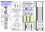
Panel Mounng
Not used
Not used
Opon Slot 2
Connector PL4A
Opon Slot 3
Connector PL4B
Opon Slot 1
Connectors
PL7 & PL8
The mounng panel must be rigid, and may be up to 6.0mm
(0.25inch) thick. Cut-out sizes are:
Cut-Out Dim A = 92mm
Cut-Out Dim B = 45mm
For n mulple instruments mounted side-by-side, cut-out A is 96n-4mm
Tolerance +0.5, -0.0mm
NOTE: For an eecve IP66 seal against dust and moisture, ensure gasket is well
compressed against the panel, with the 4 tongues located in the same ratchet slot.
Mounng Panel
Instrument
Housing
Ratchets
Gasket
1. Insert instrument into the
panel cut-out.
2. Hold front bezel rmly
(without pressing on display
area), and re-t mounng
clamp. Push clamp forward,
using a tool if necessary, unl
gasket is compressed
and instrument held rmly
in posion.

From lab to production,
providing a window into the process
-4-
www.dynisco.com
Rev: n/aP/N: n/a ECO: n/a
Rear Terminal Wiring
Connecons
All connecons to the device must be made through a spade format or similar
connecon, with connecon to the spade terminal touching both the insulaon and
conductor material. (Use a standard crimping tool). Connecons must be
mechanically secured so as to prevent any wiring becoming loose and coming in
contact with other wires or the instrument casing.
The above applies to any and all connecon to hazardous mains supply either
direct or indirect (Through a switch (Relay)) USE COPPER CONDUCTORS (EXCEPT
FOR T/C INPUT) Use Screened Cable on Retransmission Opon 1 Single Strand wire
gauge: Max 1.2mm (18SWG)
This diagram shows all possible opon combinaons. The actual connecons
required depend on the opons ed.

From lab to production,
providing a window into the process
-5-
www.dynisco.com
Rev: n/aP/N: n/a ECO: n/a
CAUTION: Check informaon label on housing for correct operang voltage before
connecng supply to Power Input. Fuse: 100 – 240V ac – 1amp an-surge 24/48V ac/
dc – 315mA an-surge
Electrical shock can result in death or serious injury. Avoid contact with the leads and
terminals. High voltages that may be present on leads can cause electrical shock
Note: At rst power-up the message Goto ConF is displayed, as described in secon 6 of this
manual. Access to other menus is denied unl conguraon mode is completed
2. Select Mode
Select mode is used to access the conguraon and operaon menu funcons. It can be accessed at
any me by holding down and pressing . The SLCt legend is shown for 1 second, followed by
the legend for the current mode. Press or to choose the required mode, then press to
enter. An unlock code is required to prevent unauthorised entry to Conguraon, & Setup modes.
Press or to enter the unlock code, then press to proceed.
NOTE: Automac return to Operator Mode aer 2 minutes without key acvity.

From lab to production,
providing a window into the process
-6-
www.dynisco.com
Rev: n/aP/N: n/a ECO: n/a
3. Conguraon Mode
First select Conguraon mode from Select mode (refer to secon 2). Press to scroll through
the parameters. While this key is pressed, and up to 1 second aer, the parameter legend is shown,
followed by the current value. Press or to set the required value. Press to display YES?
,press accept the change, otherwise parameter will revert to previous value. To exit from Con-
guraon mode, hold down and press , to return to Select mode. Note: Parameters
displayed depends on how instrument has been congured. Refer to user guide (available from
your supplier) for further details. Parameters marked * are repeated in Setup Mode.

From lab to production,
providing a window into the process
-7-
www.dynisco.com
Rev: n/aP/N: n/a ECO: n/a

From lab to production,
providing a window into the process
-8-
www.dynisco.com
Rev: n/aP/N: n/a ECO: n/a

From lab to production,
providing a window into the process
-9-
www.dynisco.com
Rev: n/aP/N: n/a ECO: n/a
4. Setup Mode
Note: Conguraon must be completed before adjusng Setup parameters. First select Setup
mode from Select mode (refer to secon 2). Press to scroll through the parameters (while this
key is pressed, and for 1 sec aer, the parameter legend is shown, then the current value). Press
or to change the value. To exit from Setup mode, hold down and press to return
to Select mode. Note: Parameters displayed depends on how instrument has been congured.

From lab to production,
providing a window into the process
-10-
www.dynisco.com
Rev: n/aP/N: n/a ECO: n/a

From lab to production,
providing a window into the process
-11-
www.dynisco.com
Rev: n/aP/N: n/a ECO: n/a
Note: Operator mode screens follow, without exing from Setup mode.
5. Strain Gauge Calibraon Mode
Note: Conguraon must be completed before adjusng Calibraon parameters. First select
Calibraon mode from Select mode (refer to secon 2). Press to scroll through the parameters
(while this key is pressed, and for 1 sec aer, the parameter legend is shown, then the current value).
Press or to change the value. To exit from Calibraon mode, hold down and press to
return to Select mode.
Note: Calibraon mode will only be displayed if input type is set to St_G

From lab to production,
providing a window into the process
-12-
www.dynisco.com
Rev: n/aP/N: n/a ECO: n/a
When the calibraon procedure begins ---- appears on the screen. Once Calibraon is complete
donE appears on screen. If there are any Faults with the calibraon an error message will appear
either Er_r or Er_C. Er_C means the low calibraon will fail if the oset is less than -10mV or greater
than +10mV. This signies potenal faulty sensors or the high calibraon will fail if the count value is
less than +20mV or greater than +50mV. This signies potenal faulty sensors. Er_r means the high
calibraon will fail if the mV value is within 10mV of the low calibraon value. This is a potenal
RCAL failure.
6. Messages & Error Indicaons
These messages indicate that the instrument may require aenon, or there is a problem with the
signal input connecon. The message legend is shown for 1 second, followed by its value.
Cauon: Do not connue with the process unl the issue is resolved.
Note: CHHJ, CLLJ or OPEN may be displayed if an incorrect input type is selected.

From lab to production,
providing a window into the process
-13-
www.dynisco.com
Rev: n/aP/N: n/a ECO: n/a
7. Operator Mode
This mode is entered at power on, or accessed from Select mode (see secon 2). Note: All
Conguraon mode and Setup mode parameters must be set as required before starng normal
operaons. Press to scroll through the parameters (while this key is pressed, and for 1 sec
aer, the parameter legend is shown, followed by the current value). Note: All Operator Mode
parameters in Display strategy 6 are read only (see diSP in conguraon mode), they can only be
adjusted via Setup mode.

From lab to production,
providing a window into the process
-14-
www.dynisco.com
Rev: n/aP/N: n/a ECO: n/a
Alarm Indicaon
The Acve Alarm Status screen indicates any acve alarms. In addion, the associated
Alarm LED ashes. For latching alarm outputs, the LED ashes when the alarm
condion exists, and goes to ON when the alarm condion is no longer present if the
output has not yet been reset.
*Reseng Latched Alarm Outputs
Any latched outputs can be reset whilst the Process variable or Alarm Status screens
are displayed, by pressing the or key, via the Logic Input.
NOTE: A reset will aect ALL latched outputs, but outputs will only reset if
their alarm condion is no longer present.
Addional Indicator Units Display and LEDs
In Operator Mode, a Units display shows °C or °F when temperature values are shown. This display
is also used in other modes as a conrmaon of the parameter type currently shown in the main
display. The SET LED indicator is o in Operator Mode, Flashing in Conguraon Mode and ON in
Set-up mode. MIN and MAX LED’s light when these stored values are shown.
Mul-Point Scaling
When enabled (MPS = EnAb), up to 9 breakpoints
can be set to compensate for non-linear input
signals. For each breakpoint, the input scale value
(ScAn) is entered in % of input span, followed by
the value to be shown (diSn) in display units.
Each breakpoint’s input scale value must be higher
than the previous value, but the display values can
be higher or lower. Any scale value set to 100%
becomes the last in the series.
Tare Feature
When Tare is enabled (tArE = EnAb), it can be used to set the displayed value to zero automacally,
by making the PV Oset parameter equal, but opposite to, the current process variable value. Tare
can be iniated via the Logic Input, or by using the following key press sequence:
Press unl the process variable is displayed.
Hold down and together for three seconds unl the display shows YES?

From lab to production,
providing a window into the process
-15-
www.dynisco.com
Rev: n/aP/N: n/a ECO: n/a
Release both keys and press within 3 seconds to conrm the request. The display should read 0
briey, then begin responding to input signal changes.
Note: Tare request is aborted if this sequence is not followed exactly.
8. Product Informaon Mode
First select Product informaon mode from Select mode (refer to secon 2). Press to view each
parameter (while this key is pressed, and for 1 sec aer, the parameter legend is shown, followed by
its value). Hold down and press to return to Select mode.
Note: These parameters are all read only.

From lab to production,
providing a window into the process
-16-
www.dynisco.com
Rev: n/aP/N: n/a ECO: n/a
9. Specicaons
Universal Input
Strain Gauge: 350 , by means of 4 or 6 wire (6 to use internal Shunt resistor)
Bridge excitaon: 10VDC ± 7% @ 45mA Max.
Bridge Sensivity: 1.4-4mV/V
Shunt Value: From 40%to 100%
Input signal Span: -25% to 125% (Approx. -10mV to +50mV)
Thermocouple ± 0.1% of full range, ±1LSD (±1°C for Thermocouple CJC).
BS4937, NBS125 & IEC584.
PT100 Calibraon: ±0.1% of full range, ±1LSD.
BS1904 & DIN43760 (0.00385 / /°C).
DC Calibraon: ±0.1% of full range, ±1LSD.
Sampling Rate: 4 per second. (250ms)
Impedance: >10M resisve, except DC mA (5 ) and V (47k ).
Sensor Break Strain Gauge: Depending on user seng lnPF can cause input to fail
high scale or low scale reading. Reading will fail on either, Sig+ or Sig-
loss, or incorrect excitaon output <0.8mA and >50mA supply.
Thermocouple/RTD: High alarms acvate for sensor break. Linear 4 to 20mA, 2 to 10V and
1 to 5V DC: Low alarms acvate for sensor break.
Note: Sensor break not detectable on 0 to 20mA, 2 to 10V
and 1 to 5V DC input types.
Isolaon: Isolated from all outputs.
Universal input must not be connected to operator accessible circuits
if single relay outputs are connected to a hazardous voltage source.
Supplementary insulaon or input grounding would then be required.
Logic Input
Input Signal: If the Logic State seng in Cong Mode = CLS, Reset or Tare occurs on
an Open to Closed transion, or high (3 to 5VDC) to low (<0.8VDC)
transion.
If Logic State seng in Cong Mode = OPN, Reset or Tare occurs on a
Closed to Open transion, or low (<0.8VDC) to high (3 to 5VDC))
transion.
Isolaon: No isolaon from inputs and other outputs.
Calibration:
Detection:

From lab to production,
providing a window into the process
-17-
www.dynisco.com
Rev: n/aP/N: n/a ECO: n/a
Outputs
Relay
Contact Type & Single pole double throw (SPDT), latching or non-latching acon
(selectable); 2A resisve at 120/240VAC.
Lifeme: >500,000 operaons at rated voltage/current.
Isolaon: Basic Isolaon from universal input and SSR outputs.
Linear DC
Accuracy: ±0.25% (mA @ 250 , V @ 2k ). Degrades linearly to ±0.5%
for increasing burden (to specicaon limits).
Resoluon: 8 bits in 250mS (10 bits in 1s typical, >10 bits in >1s typical).
Isolaon: Reinforced safety isolaon from inputs and other outputs.
OPERATING CONDITIONS (FOR INDOOR USE)
Ambient Temperature: 0°C to 55°C (Operang), –20°C to 80°C (Storage).
Relave Humidity: 20% to 95% non-condensing.
Altude: <2000m
Supply Voltage and 100 to 240VAC ±10%, 50/60Hz, 8.5VA (for mains powered versions), or
20 to 48VAC 50/60Hz 7.5VA or 22 to 65VDC 5W
(for low voltage versions).
ENVIRONMENTAL
Standards: CE
EMI: Complies with EN61326 (Suscepbility & Emissions).
Safety Complies with EN61010-3
Polluon Degree 2, Installaon Category II.
Front Panel Sealing: To IP66 (IP20 behind the panel).
PHYSICAL
Front Bezel Size: 96 x 48mm (1/8 Din Horizontal).
Depth Behind Panel: 100mm.
Weight: 0.21kg maximum.
MANUFACTURING SITE
Address: The Hyde Business Park, Brighton, BN2 4JU, United Kingdom
SYMBOL EXPLANATION
Rang:
Power:
Consideraons:
Cauon general danger to life
or limb
General informaon and
noces.
/