Page is loading ...

cover 5/94 − ST-143 327-A PRINTED IN USA
© 1995 MILLER Electric Mfg. Co.
Read and follow these instructions and all
safety blocks carefully.
Have only trained and qualified persons
install, operate, or service this unit.
Call your distributor if you do not understand
the directions.
Give this manual to the operator.
For help, call your distributor
or: MILLER Electric Mfg. Co., P.O. Box 1079,
Appleton, WI 54912 414-734-9821
OWNER’S
MANUAL
November 1995 Form: OM-1582J
Effective With Serial No. KF923720
24 Volts AC, 10 Amperes, 50/60 Hertz Wire Feeder
For Use With CV/DC Welding Power Source With Contactor
For GMAW And FCAW Welding
Rated At 100 Volts, 750 Amperes, 100% Duty Cycle
Circuit Breaker CB1 Protects Unit From Overload
Wire Feed Speed Range: 50 To 780 ipm (1.3 To 20 mpm)
Wire Diameter Range: .023 To 1/8 in (0.6 To 3.2 mm)
For Options And Accessories, See Rear Cover
D-64 Wire Feeder

miller_war1 6/95
MILLER’S TRUE BLUE® LIMITED WARRANTY
Effective January 1, 1995
(Equipment with a serial number preface of “KD” or newer)
This limited warranty supersedes all previous MILLER warranties and is exclusive with no other guarantees or warranties expressed or implied.
LIMITED WARRANTY − Subject to the terms and conditions below, MILLER Electric
Mfg. Co., Appleton, Wisconsin, warrants to its original retail purchaser that new
MILLER equipment sold after the effective date of this limited warranty is free of de-
fects in material and workmanship at the time it is shipped by MILLER. THIS WAR-
RANTY IS EXPRESSLY IN LIEU OF ALL OTHER WARRANTIES, EXPRESS OR
IMPLIED, INCLUDING THE WARRANTIES OF MERCHANTABILITY AND FIT-
NESS.
Within the warranty periods listed below, MILLER will repair or replace any war-
ranted parts or components that fail due to such defects in material or workmanship.
MILLER must be notified in writing within thirty (30) days of such defect or failure, at
which time MILLER will provide instructions on the warranty claim procedures to be
followed.
MILLER shall honor warranty claims on warranted equipment listed below in the
event of such a failure within the warranty time periods. All warranty time periods
start on the date that the equipment was delivered to the original retail purchaser, or
one year after the equipment is sent to a North American distributor or eighteen
months after the equipment is sent to an International distributor.
1. 5 Years Parts − 3 Years Labor
* Original main power rectifiers
* Inverters (input and output rectifiers only)
2. 3 Years — Parts and Labor
* Transformer/Rectifier Power Sources
* Plasma Arc Cutting Power Sources
* Semi-Automatic and Automatic Wire Feeders
* Inverter Power Supplies
* Intellitig
* Robots
3. 2 Years — Parts and Labor
* Engine Driven Welding Generators
(NOTE: Engines are warranted separately by the engine manufacturer.)
* Air Compressors
4. 1 Year — Parts and Labor
* Motor Driven Guns
* Process Controllers
* IHPS Power Sources
* Water Coolant Systems
* HF Units
* Grids
* Spot Welders
* Load Banks
* SDX Transformers
* Running Gear/Trailers
* Plasma Cutting Torches (except APT, ZIPCUT & PLAZCUT Models)
* Tecumseh Engines
* Deutz Engines (outside North America)
* Field Options
(NOTE: Field options are covered under True Blue® for the remaining
warranty period of the product they are installed in, or for a minimum of
one year — whichever is greater.)
5. 6 Months — Batteries
6. 90 Days — Parts and Labor
* MIG Guns/TIG Torches
* APT, ZIPCUT & PLAZCUT Model Plasma Cutting Torches
* Remote Controls
* Accessory Kits
* Replacement Parts
MILLER’S True Blue® Limited Warranty shall not apply to:
1. Items furnished by MILLER, but manufactured by others, such as engines or
trade accessories. These items are covered by the manufacturer’s warranty, if
any.
2. Consumable components; such as contact tips, cutting nozzles, contactors
and relays or parts that fail due to normal wear.
3. Equipment that has been modified by any party other than MILLER, or equip-
ment that has been improperly installed, improperly operated or misused
based upon industry standards, or equipment which has not had reasonable
and necessary maintenance, or equipment which has been used for operation
outside of the specifications for the equipment.
MILLER PRODUCTS ARE INTENDED FOR PURCHASE AND USE BY COMMER-
CIAL/INDUSTRIAL USERS AND PERSONS TRAINED AND EXPERIENCED IN
THE USE AND MAINTENANCE OF WELDING EQUIPMENT.
In the event of a warranty claim covered by this warranty, the exclusive remedies
shall be, at MILLER’S option: (1) repair; or (2) replacement; or, where authorized in
writing by MILLER in appropriate cases, (3) the reasonable cost of repair or replace-
ment at an authorized MILLER service station; or (4) payment of or credit for the pur-
chase price (less reasonable depreciation based upon actual use) upon return of the
goods at customer’s risk and expense. MILLER’S option of repair or replacement
will be F.O.B., Factory at Appleton, Wisconsin, or F.O.B. at a MILLER authorized ser-
vice facility as determined by MILLER. Therefore no compensation or reimburse-
ment for transportation costs of any kind will be allowed.
TO THE EXTENT PERMITTED BY LAW, THE REMEDIES PROVIDED HEREIN
ARE THE SOLE AND EXCLUSIVE REMEDIES. IN NO EVENT SHALL MILLER BE
LIABLE FOR DIRECT, INDIRECT, SPECIAL, INCIDENTAL OR CONSEQUENTIAL
DAMAGES (INCLUDING LOSS OF PROFIT), WHETHER BASED ON CON-
TRACT, TORT OR ANY OTHER LEGAL THEORY.
ANY EXPRESS WARRANTY NOT PROVIDED HEREIN AND ANY IMPLIED WAR-
RANTY, GUARANTY OR REPRESENTATION AS TO PERFORMANCE, AND ANY
REMEDY FOR BREACH OF CONTRACT TORT OR ANY OTHER LEGAL
THEORY WHICH, BUT FOR THIS PROVISION, MIGHT ARISE BY IMPLICATION,
OPERATION OF LAW, CUSTOM OF TRADE OR COURSE OF DEALING, IN-
CLUDING ANY IMPLIED WARRANTY OF MERCHANTABILITY OR FITNESS
FOR PARTICULAR PURPOSE, WITH RESPECT TO ANY AND ALL EQUIPMENT
FURNISHED BY MILLER IS EXCLUDED AND DISCLAIMED BY MILLER.
Some states in the U.S.A. do not allow limitations of how long an implied warranty
lasts, or the exclusion of incidental, indirect, special or consequential damages, so
the above limitation or exclusion may not apply to you. This warranty provides spe-
cific legal rights, and other rights may be available, but may vary from state to state.
In Canada, legislation in some provinces provides for certain additional warranties
or remedies other than as stated herein, and to the extent that they may not be
waived, the limitations and exclusions set out above may not apply. This Limited
Warranty provides specific legal rights, and other rights may be available, but may
vary from province to province.
WHO DO I CONTACT?
For help,
H contact your distributor
For additional information, such as
Technical Manuals (Service And Parts)
Engine Manuals
Circuit And Wiring Diagrams
Process Handbooks
User’s Guides
Distributor Directories
H contact your distributor
To file a claim for loss or damage during
shipment,
H contact the delivering carrier
For assistance in filing or settling claims,
H contact your distributor and/or equipment
manufacturer’s Transportation
Department
Miller Electric Mfg. Co.
H CALL:
414-735-4505
H FAX:
800-637-2348 (in USA), or
414-735-4136 (outside USA)
H WRITE:
Miller Electric Mfg. Co.
P.O. Box 1079
Appleton, WI 54912 USA
Always provide Model Name and Serial or Style Number


OM-1582J − 11/95
EMF INFORMATION
The following is a quotation from the General Conclusions Section
of the U.S. Congress, Office of Technology Assessment, Biological
Effects of Power Frequency Electric & Magnetic Fields −
Background Paper, OTA-BP-E-53 (Washington, DC: U.S.
Government Printing Office, May 1989): “. . . there is now a very
large volume of scientific findings based on experiments at the
cellular level and from studies with animals and people which clearly
establish that low frequency magnetic fields can interact with, and
produce changes in, biological systems. While most of this work is
of very high quality, the results are complex. Current scientific
understanding does not yet allow us to interpret the evidence in a
single coherent framework. Even more frustrating, it does not yet
allow us to draw definite conclusions about questions of possible
risk or to offer clear science-based advice on strategies to minimize
or avoid potential risks.”
To reduce magnetic fields in the workplace, use the following
procedures:
1. Keep cables close together by twisting or taping them.
2. Arrange cables to one side and away from the operator.
3. Do not coil or drape cables around the body.
4. Keep welding power source and cables as far away as
practical.
5. Connect work clamp to workpiece as close to the weld as
possible.
About Pacemakers:
The above procedures are among those also normally
recommended for pacemaker wearers. Consult your doctor for
complete information.
Considerations About Welding And The Effects Of Low Frequency Electric And
Magnetic Fields
NOTE
mod10.1 4/93
TABLE OF CONTENTS
SECTION 1 − SAFETY INFORMATION 1. . . . . . . . . . . . . . . . . . . . . . . . . . . . . . . . . . . . . . . . . . . . . . . . . . . . .
SECTION 2 − SPECIFICATIONS 1. . . . . . . . . . . . . . . . . . . . . . . . . . . . . . . . . . . . . . . . . . . . . . . . . . . . . . . . . .
SECTION 3 − INSTALLATION 2. . . . . . . . . . . . . . . . . . . . . . . . . . . . . . . . . . . . . . . . . . . . . . . . . . . . . . . . . . . . .
3-1. Site Selection 2. . . . . . . . . . . . . . . . . . . . . . . . . . . . . . . . . . . . . . . . . . . . . . . . . . . . . . . . . . . . . . . . .
3-2. Equipment Connection Diagrams 3. . . . . . . . . . . . . . . . . . . . . . . . . . . . . . . . . . . . . . . . . . . . . . . . .
3-3. Wire Guide And Drive Roll Installation 5. . . . . . . . . . . . . . . . . . . . . . . . . . . . . . . . . . . . . . . . . . . .
3-4. Welding Gun Connections 6. . . . . . . . . . . . . . . . . . . . . . . . . . . . . . . . . . . . . . . . . . . . . . . . . . . . . . .
3-5. Motor Start Control 7. . . . . . . . . . . . . . . . . . . . . . . . . . . . . . . . . . . . . . . . . . . . . . . . . . . . . . . . . . . . .
3-6. Dip Switches Options 8. . . . . . . . . . . . . . . . . . . . . . . . . . . . . . . . . . . . . . . . . . . . . . . . . . . . . . . . . . .
3-7. Changing Optional Digital Voltage Control For Use With A
MILLER Inverter-Type Power Source 11. . . . . . . . . . . . . . . . . . . . . . . . . . . . . . . . . . . . . . . . . . . . .
3-8. 14-Pin Plug Connection 12. . . . . . . . . . . . . . . . . . . . . . . . . . . . . . . . . . . . . . . . . . . . . . . . . . . . . . . . .
3-9. Shielding Gas And Weld Cable Connections 13. . . . . . . . . . . . . . . . . . . . . . . . . . . . . . . . . . . . . . .
3-10. Voltage Sensing Lead (Optional) 14. . . . . . . . . . . . . . . . . . . . . . . . . . . . . . . . . . . . . . . . . . . . . . . . .
3-11. Welding Wire Installation 15. . . . . . . . . . . . . . . . . . . . . . . . . . . . . . . . . . . . . . . . . . . . . . . . . . . . . . . .
3-12. Threading Welding Wire With Drive Assembly Horizontal 17. . . . . . . . . . . . . . . . . . . . . . . . . . . .
3-13. Rotating The Drive Assembly And Threading Welding Wire 19. . . . . . . . . . . . . . . . . . . . . . . . . .
SECTION 4 − OPERATION 21. . . . . . . . . . . . . . . . . . . . . . . . . . . . . . . . . . . . . . . . . . . . . . . . . . . . . . . . . . . . . . .
SECTION 5 − MAINTENANCE & TROUBLESHOOTING 27. . . . . . . . . . . . . . . . . . . . . . . . . . . . . . . . . . . . . .
5-1. Routine Maintenance 28. . . . . . . . . . . . . . . . . . . . . . . . . . . . . . . . . . . . . . . . . . . . . . . . . . . . . . . . . . .
5-2. Replacing The Hub Assembly 28. . . . . . . . . . . . . . . . . . . . . . . . . . . . . . . . . . . . . . . . . . . . . . . . . . .
5-3. Overload Protection 29. . . . . . . . . . . . . . . . . . . . . . . . . . . . . . . . . . . . . . . . . . . . . . . . . . . . . . . . . . . .
5-4. Troubleshooting 29. . . . . . . . . . . . . . . . . . . . . . . . . . . . . . . . . . . . . . . . . . . . . . . . . . . . . . . . . . . . . . .
SECTION 6 − ELECTRICAL DIAGRAMS 31. . . . . . . . . . . . . . . . . . . . . . . . . . . . . . . . . . . . . . . . . . . . . . . . . . .
SECTION 7 − PARTS LIST 36. . . . . . . . . . . . . . . . . . . . . . . . . . . . . . . . . . . . . . . . . . . . . . . . . . . . . . . . . . . . . . .
Figure 7-1. Main Assembly 36. . . . . . . . . . . . . . . . . . . . . . . . . . . . . . . . . . . . . . . . . . . . . . . . . . . . . . . . . . . .
Figure 7-2. Control Box 38. . . . . . . . . . . . . . . . . . . . . . . . . . . . . . . . . . . . . . . . . . . . . . . . . . . . . . . . . . . . . . .
Figure 7-3. Control Panel 40. . . . . . . . . . . . . . . . . . . . . . . . . . . . . . . . . . . . . . . . . . . . . . . . . . . . . . . . . . . . . .
Figure 7-4. Panel, Front w/Components 42. . . . . . . . . . . . . . . . . . . . . . . . . . . . . . . . . . . . . . . . . . . . . . . . .
Table 7-1. Wire Drive Assembly Kits 44. . . . . . . . . . . . . . . . . . . . . . . . . . . . . . . . . . . . . . . . . . . . . . . . . . . .
Figure 7-5. Drive Assembly, Wire (4 Drive Roll Assembly Illustrated) 44. . . . . . . . . . . . . . . . . . . . . . . . .
Table 7-2. Drive Roll And Wire Guide Kits 46. . . . . . . . . . . . . . . . . . . . . . . . . . . . . . . . . . . . . . . . . . . . . . . .


OM-1582 Page 1
SECTION 1 − SAFETY INFORMATION
mod1.1 2/93
Read all safety messages throughout this manual.
Obey all safety messages to avoid injury.
Learn the meaning of WARNING and CAUTION.
1 Safety Alert Symbol
2 Signal Word
WARNING means possible death
or serious injury can happen.
CAUTION means possible minor
injury or equipment damage can
happen.
3 Statement Of Hazard And
Result
4 Safety Instructions To Avoid
Hazard
5 Hazard Symbol (If Available)
6 Safety Banner
Read safety blocks for each sym-
bol shown.
7 NOTE
Special instructions for best oper-
ation − not related to safety.
2
NOTE
ELECTRIC SHOCK can kill.
• Do not touch live electrical parts.
• Disconnect input power before
installing or servicing.
WARNING
READ SAFETY BLOCKS at start of
Section 3-1 before proceeding.
WARNING
5
4
6
7
1 2
CAUTION
MOVING PARTS can injure.
• Keep away from moving parts.
• Keep all panels and covers closed
when operating.
3
Turn Off switch when using high frequency.
Figure 1-1. Safety Information
SECTION 2 − SPECIFICATIONS
Table 2-1. Wire Feeder
Specification Description
Type Of Input Power From Welding
Power Source
Single-Phase 24 Volts AC, 10 Amperes, 50/60 Hertz (If 115 Volts AC Is The Only Power Available,
Use Optional Power Supply Adapter Model PSA-2.)
Maximum Weld Circuit Rating 100 Volts, 750 Amperes, 100% Duty Cycle
Welding Power Source Type Constant Voltage (CV) DC, With Contactor
Wire Feed Speed Range Standard Motor: 50 To 780 ipm (1.3 To 20 mpm)
High Speed Motor: 90 To 1400 ipm (2.3 To 35.6 mpm)
Welding Processes Gas Metal Arc (GMAW), Flux Cored Arc Welding (FCAW)
Input Power Cord 10 ft (3.1 m)
Overall Dimensions Length: 32 in (812 mm); Width: 18 in (457 mm); Height: 14 in (356 mm)
Weight Shipping: 82 lb (37.2 kg); Net: 74 lb (33.6 kg) Add 4 lb (1.8 kg) For 4-Drive Roll Models

OM-1582 Page 2
SECTION 3 − INSTALLATION
3-1. Site Selection
WARNING: FALLING WIRE FEEDER can
cause serious personal injury and
equipment damage.
• Do not put wire feeder where it will tip or fall.
• Put all four rubber feet solidly on a flat surface.
CYLINDERS can explode if damaged.
• Keep cylinders away from welding and other
electrical circuits.
• Never touch cylinder with welding electrode.
• Always secure cylinder to running gear, wall, or
other stationary support.
ELECTRIC SHOCK can kill.
• Do not touch live electrical parts.
The welding wire, drive rolls, drive assembly, and all
metal parts touching the welding wire are electrically
live when welding or feeding wire using gun trigger.
WARNING
wfwarn7.1* 9/91
ST−152 586 / ST-152 566
1 Wire Feeder
2 Lifting Eye
3 Rubber Feet
4 Installation Slots
When installing wire feeder over a
lifting eye on a welding power
source, select the slot that will al-
low all four rubber feet on base of
feeder to sit securely on top of
welding power source.
5 Wire Spool/Reel
6 Gas Cylinder (Customer
Supplied)
7 Welding Power Source
Position wire feeder on welding
power source so that welding wire,
or wire spool/reel, does not touch
gas cylinder.
1
Do not put feeder where
welding wire hits cylinder.
5
2
4
7
6
3
Figure 3-1. Installing Wire Feeder Over A Lifting Eye

OM-1582 Page 3
3-2. Equipment Connection Diagrams
WARNING
CYLINDERS can explode if damaged.
• Keep cylinders away from welding and other
electrical circuits.
• Never touch cylinder with welding electrode.
• Always secure cylinder to running gear, wall, or
other stationary support.
HOT SURFACES can burn skin.
• Allow gun to cool before touching.
ELECTRIC SHOCK can kill.
• Do not touch live electrical parts.
• Turn Off wire feeder and welding power source, and
disconnect input power before making
connections. Stop engine on welding generator.
The welding wire, drive rolls, drive assembly, and all
metal parts touching the welding wire are electrically
live when welding or feeding wire using gun trigger.
Have only qualified persons install this unit.
wfwarn9.1 2/93
If using wire feeder with an engine-driven power source, place engine control
switch in Run (high speed) position. Some wire feeders may work with switch in
Run/Idle position.
NOTE
ST-152 616
1 CV Or CC/CV Welding Power
Source Supplying 24 VAC To
Feeder
2 14-Pin Plug PLG10 And In-
terconnecting Cord
3 Positive (+) Weld Cable
4 Negative (−) Weld Cable
5 Workpiece
6 Voltage Sensing Lead
7 Gun
8 Wire Feeder
9 “Y” Adapter Gas Hose
10 Gas Cylinder
1
2
3
4
5
6
7
8
9
10
Figure 3-2. Connections With A Constant Voltage (CV) Or Constant Voltage/Constant Current (CV/CC)
Welding Power Source Having A 14-Socket Receptacle And 24 VAC Supply

OM-1582 Page 4
ST-152 320
1 CV Welding Power Source
2 PSA-2 Interconnecting Cord
(Supplied With PSA-2 Con-
trol)
3 Positive (+) Weld Cable
4 Negative (−) Weld Cable
5 Workpiece
6 Voltage Sensing Lead
7 Gun
8 Wire Feeder
9 14-Pin Plug PLG10 And In-
terconnecting Cord.
10 PSA-2 Control (Optional)
11 “Y” Adapter Gas Hose
12 Gas Cylinder
1
2
3
4
5
6
7
8
9
10
11
12
Figure 3-3. Connections With A Constant Voltage (CV) Welding Power Source
Having Only 115 VAC Available

OM-1582 Page 5
3-3. Wire Guide And Drive Roll Installation
WARNING
CYLINDERS can explode if damaged.
• Keep cylinders away from welding and other
electrical circuits.
• Never touch cylinder with welding electrode.
• Always secure cylinder to running gear, wall, or
other stationary support.
HOT SURFACES can burn skin.
• Allow gun to cool before touching.
ELECTRIC SHOCK can kill.
• Do not touch live electrical parts.
• Turn Off wire feeder and welding power source, and
disconnect input power before making
connections. Stop engine on welding generator.
The welding wire, drive rolls, drive assembly, and all
metal parts touching the welding wire are electrically
live when welding or feeding wire using gun trigger.
Have only qualified persons install this unit.
wfwarn9.1 2/93
A. Wire Guide Installation
ST-153 125-B / ST-137 377-D
When changing wire size or type,
check guide size (see Table 7-2).
1 Drive Rolls
Remove drive rolls before install-
ing wire guides (see Figure 3-5).
2 Wire Guide Securing Screws
Loosen wire guide screws.
3 Antiwear Guide
4 Inlet Wire Guide
Install inlet wire guide into antiwear
guide.
Install inlet guide so wire guide
screw is centered in groove in
guide.
5 Intermediate Wire Guide
Insert intermediate guide until
flange on guide rests against cast-
ing, and secure with guide screw.
Install drive rolls (see Figure 3-5).
Repeat procedure for opposite
side of wire feeder.
1
Tools Needed:
2
5
4
3
5/64 in
Figure 3-4. Wire Guide Installation

OM-1582 Page 6
B. Drive Roll Installation
When changing wire size or type,
check drive roll size (see
Table 7-2).
1 Spring Shaft Carrier
Close spring shaft carrier.
2 Drive Roll Nut
3 Drive Roll Carrier
Turn nut one click until lobes of nut
line up with lobes of drive roll carri-
er.
Open spring shaft carrier.
4 Drive Roll
Slide drive roll onto drive roll carri-
er. Turn nut one click.
Repeat procedure for top drive roll.
5 Drive Assembly Cover
Close cover.
Repeat procedure for opposite
side of wire feeder.
ST-137 377-D
1
5
4
23
Figure 3-5. Drive Roll Installation
3-4. Welding Gun Connections
WARNING
ELECTRIC SHOCK can kill.
• Do not touch live electrical parts.
• Turn Off wire feeder and welding power source, and disconnect input power before inspecting or installing. Stop engine on
welding generator.
wfwarn1.1* 2/93
Ref. ST-148 702 / Ref. ST-152 466
1 Gun Securing Knob
2 Gun Block
3 Gun End
Loosen gun securing knob. Insert
end into block. Position as close as
possible to drive rolls without touch-
ing. Tighten knob.
4 Gun Trigger Plug
Insert plug into receptacle, and tight-
en threaded collar.
5 Gun Trigger Receptacle
6 Drive Assembly Cover
Close cover.
Repeat procedure for welding gun
on opposite side of wire feeder.
5
1
2
3
4
6
Figure 3-6. Gun And Trigger Lead Connections

OM-1582 Page 7
3-5. Motor Start Control
WARNING
ELECTRIC SHOCK can kill.
• Do not touch live electrical parts.
• Turn Off wire feeder and welding power source, and
disconnect input power before inspecting or
installing. Stop engine on welding generator.
STATIC ELECTRICITY can damage parts
on circuit boards.
• Put on grounded wrist strap BEFORE handling
boards or parts.
wfwarn1.1* 2/93
Ref. ST-143 259-E / Ref. SB-146 862-D
To change wire feed starting
speed, proceed as follows:
Turn Off wire feeder and welding
power source.
Remove wrapper.
1 Front Panel
Front panel shown open for illus-
tration purposes.
2 Left Side Inner Control Panel
It may be necessary to remove
panel to access Motor Start Con-
trol. Remove panel only as far as
required if options are attached to
panel.
3 Motor Board PC1
4 Motor Start Control Poten-
tiometer R70
Turn potentiometer clockwise to in-
crease time it takes the motor to
ramp up to speed. Remove protec-
tive white rubber cap before mak-
ing adjustment. Adjust potentiome-
ter R70 using a small nonconduc-
tive screwdriver.
Reinstall left side inner control pan-
el if it was removed.
Reinstall wrapper.
1
Tools Needed:
1/4 in
2
4
3
Figure 3-7. Motor Start Control On Motor Control Board PC1

OM-1582 Page 8
3-6. Dip Switches Options
WARNING
ELECTRIC SHOCK can kill.
• Do not touch live electrical parts.
• Turn Off wire feeder and welding power source, and
disconnect input power before inspecting or
installing. Stop engine on welding generator.
STATIC ELECTRICITY can damage parts
on circuit boards.
• Put on grounded wrist strap BEFORE handling
boards or parts.
wfwarn1.1* 2/93
A. Spot/Time DIP Switch S1
Ref. ST-143 259-E / SA-146 866-B
Change DIP switch position if a dif-
ferent range of Spot/Time is de-
sired.
Turn Off wire feeder and welding
power source.
Remove wrapper.
1 Front Panel
Remove screw from upper left cor-
ner, and open hinged front panel if
necessary.
2 4-In-1 Board PC30
3 Spot/Time DIP Switch S1
Place switch (on either or both
PC30 boards) in desired position:
Long Time for 0-5 seconds, and
Short Time for 0-2.5 seconds (see
Figure 4-11 for control operation).
Close and secure front panel, and
reinstall wrapper.
1
Tools Needed:
1/4 in
3 2
Figure 3-8. Spot/Time DIP Switch S1

OM-1582 Page 9
B. Digital Meter Functions And Positions
Ref. ST-143 259-E / Ref. S-0389 / SA-148 666-E
The Digital Meter Board PC60 for
the Two Meter Option is equipped
with DIP switch S3. This switch is
shipped from the factory in the Off
position, and should not be
changed.
Change DIP switch positions if a
different mode of operation is de-
sired.
Turn Off wire feeder and welding
power source.
Remove the six (6) screws from
front edge of wrapper.
1 Front Panel
Front panel shown open for illus-
tration purposes.
2 Digital Meter Board PC60
3 Meter Functions DIP Switch
S2
Place switch in appropriate posi-
tion for desired mode (see
Figure 4-7 for meter operation).
Reinstall wrapper screws.
Tools Needed:
1/4 in
1
2
3
123 45
123 45
123 45
123 45
123 45
123 45
12
Or
Or Or
Standard
Motor
Inches/Minute
Standard
Motor
Meters/Minute
High Speed
Motor
Inches/Minute
High Speed
Motor
Meters/Minute
Voltage Hold Voltage Monitor
X Means switch can be in either position.
Means place switch in this position.
Figure 3-9. Digital Meter Functions DIP Switch S2

OM-1582 Page 10
C. Remote Input DIP Switch S1
Ref. S-0380 / SA-150 588-D / Ref. ST-143 259-E
Change DIP switch position if a dif-
ferent mode of operation is de-
sired.
Turn Off wire feeder and welding
power source.
Remove wrapper.
1 Front Panel
Front panel shown open for illus-
tration purposes.
2 Option Interface Board PC70
3 Remote Input DIP Switch S1
Place DIP switch S1 (on either or
both PC70 boards) in appropriate
position for desired mode.
Reinstall wrapper.
1
Tools Needed:
1/4 in
2
3
OFF
12
OFF
12
Or
Remote
Input
Standard
Dual Schedule Or
Remote Pendant
Means place switch
in this position.
Figure 3-10. Remote Input DIP Switch S1

OM-1582 Page 11
3-7. Changing Optional Digital Voltage Control For Use With A MILLER Inverter-Type
Power Source
WARNING
ELECTRIC SHOCK can kill.
• Do not touch live electrical parts.
• Turn Off wire feeder and welding power source, and
disconnect input power before inspecting or
installing. Stop engine on welding generator.
STATIC ELECTRICITY can damage parts
on circuit boards.
• Put on grounded wrist strap BEFORE handling
boards or parts.
wfwarn1.1* 2/93
A. Electrical Connections
Ref. ST-143 259-E / SA-171 708
Turn Off wire feeder and welding
power source.
Remove the six (6) screws from
front edge of wrapper.
If optional Digital Voltage Control is
used with a MILLER inverter-type
welding power source, make the
following changes:
1 Front Panel
Remove screw from upper left cor-
ner, and open hinged front panel.
2 Digital Voltage Control Board
PC40
3 Receptacle RC42
Disconnect plug PLG42 from
RC42.
4 Receptacle RC44
Reconnect PLG42 to RC44.
5 Receptacle RC45
Disconnect jumper plug PLG61
from RC45.
6 Receptacle RC41
Disconnect plug PLG41 from
RC41.
Reconnect PLG41 to RC45.
Reconnect jumper plug PLG61 to
RC41.
7 Potentiometer R31
See Section 3-7B.
Close and secure front panel, and
reinstall wrapper screws.
1
2
3
4
6
5
Tools Needed:
1/4 in
7
Figure 3-11. Digital Voltage Control Connections

OM-1582 Page 12
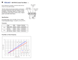
B. Calibrating The Digital Voltage Meter For Use With A MILLER Inverter-Type Power Source
If wire feeder is being used with a MILLER inverter-type power source that has a
voltage range of 10 to 35 volts in the CV mode, no calibration is required.
NOTE
1. If wire feeder is equipped with Two Meter option, read voltage from the Volts meter. If wire feeder is equipped
with One Meter option (see Figure 4-7 for meter operation), place Wire Speed/Volts switch in the Volts position.
2. Rotate Schedule A or Schedule B Voltage Control, whichever is active, to the maximum position (see Figure 4-8
for control operation).
3. Turn On wire feeder and welding power source (see Figure 4-15).
4. Adjust potentiometer R31 (see Figure 3-11 for location) until wire feeder Volts meter displays a voltage equal to
the maximum voltage listed on the Voltage/Amperage control of the welding power source nameplate. Make a
sample weld (at desired preset voltage) to see if actual arc voltage displayed by the wire feeder Volts meter is
different than preset arc voltage due to cable resistance, poor connections, etc. If there is a difference, R31 can
be adjusted until preset voltage is closer to actual arc voltage.
5. Close front panel, and install wrapper.
3-8. 14-Pin Plug Connection
Ref. ST-143 260-A / Ref. S-0512
1 Plug PLG10
2 Keyway
3 Threaded Collar
Connect 14-pin plug PLG10 to
matching receptacle on welding
power source as follows: align key-
ways, insert plug, and tighten
threaded collar.
AJ
B
K
I
C
L
NH
D
M
G
E
F
1
3
21
A, B Contact closure completes 24 volts ac contactor control circuit.
G Circuit common for 24/115 volts ac circuit.
C Command signal; +10 volts dc.
D Control circuit common.
E Remote power source voltage command signal from feeder (potentiometer
wiper or 0-10 volts dc source); 0 to +10 volts dc.
F Current feedback; 0 to +10 volts dc, 1 volt per 100 amperes.
H Voltage feedback; 0 to +10 volts dc, 1 volt per 10 arc volts.
Pin Information
*The remaining pins are not used.
Pin*
Figure 3-12. 14-Pin Plug With Pin Information
/