Kohler K-2971-KS-NA Installation guide
- Category
- Storage chests & cabinets & trunks
- Type
- Installation guide
Page is loading ...

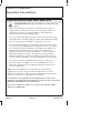
IMPORTANT INSTRUCTIONS
WARNING: Risk of scalding or other severe injury.
•
Before completing installation, the installer must set the
maximum water temperature setting of this valve to minimize the
risks associated with scalding hazards according to ASTM F 444.
•
Do not install a shut-off device on either outlet of this valve. The
installation of any such device may create a cross-flow condition
at the valve and affect the water temperature.
•
Factors that change the temperature of the water supplied to the
valve, such as seasonal water temperature changes, and water
heater replacement or servicing, will change the maximum water
temperature supplied by the valve and may create a scalding
hazard. The pressure-balanced valve will not compensate for
changes in the water supply temperature; adjust the maximum
water temperature setting of this pressure-balanced valve when
such changes occur.
•
Pressure-balanced valves may not provide protection against
scalding if there is a failure of other temperature-limiting devices
elsewhere in the plumbing system.
NOTICE: Only apply silicone based lubricants to these valves. Do
not use petroleum based lubricants. Petroleum based lubricants will
harm the O-rings, seals, and plastic components.
The installer is responsible for installing the valve and adjusting the
maximum water temperature of this pressure-balanced valve
according to instructions.
This valve meets or exceeds ANSI A112.18.1 and ASSE 1016.
If you do not understand any of the installation or temperature
adjustment instructions in this document, in the United States please
contact our Customer Care Center at 1-800-4KOHLER. Outside the
U.S., please contact your distributor.
IMPORTANT NOTICE TO INSTALLERS! Please fill in the blanks in
the information box in the Homeowners Guide and on the valve label.
Retain the Homeowners Guide for future reference.
1150733-2-A 2 Kohler Co.

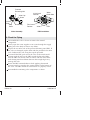
Tools and Materials
Before You Begin
WARNING: Risk of product damage. When using this valve
in a fiberglass or acrylic installation, use the thin wall
installation kit (88526).
CAUTION: Risk of product damage. This valve contains
plastic and rubber components. Do not apply excessive heat
to the valve body when soldering.
CAUTION: Risk of product damage. Do not apply flux or
acids directly to the valve, as damage may result.
CAUTION: Risk of product damage. Do not apply
petroleum-based lubricants to the valve components, as
damage may result.
IMPORTANT! The installer is responsible for installing the valve
and adjusting the maximum water temperature of this valve
according to instructions.
Observe all local plumbing and building codes.
This valve requires a minimum operating pressure of 15 psi (103.4
kPa).
The valve shuts off by water pressure. Do not force the handle in
any direction. To turn the valve off, gently turn it to the ″Off″
position.
Flush all piping thoroughly after installing the valve body.
Pipe
Wrench
Adjustable
Wrench
Strap
Wrench
Hacksaw or Tubing Cutter
Propane
Torch
Solder
Hex
Wrench
Thread
Sealant
Plumbers
Putty
Assorted
Screwdrivers
Thermometer
Kohler Co. 3 1150733-2-A

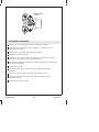
Before You Begin (cont.)
If inlet conditions differ from those used during factory
calibration, it may be necessary to re-calibrate the valve after
installation.
Do not use plastic pipe between the valve and the spout. Kohler
recommends the use of 3/4″ copper tube. Iron pipe is not
recommended.
This valve does not have an integral aspirator. For installations
that use a bath diverter spout, you must install a twin ell (K-9663)
with integral aspirator between the valve and the bath spout. If
these thermostatic mixing valves are installed without an
aspirator it will cause water to flow from the shower and bath
spout at the same time.
Kohler Co. reserves the right to make revisions in the design of
products without notice, as specified in the Price Book.
1. Prepare the Site
IMPORTANT! If the bath has been installed, cover it to prevent
damage to the bath surface.
Rough Plumbing
Shut off the main water supply.
Install or relocate the supplies as necessary.
Support Framing
Determine the location of the valve, and install the support
framing.
1150733-2-A 4 Kohler Co.

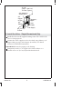
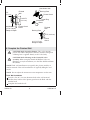
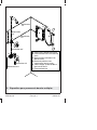
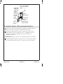
2. Install the Valve - Single Showerhead Only
Install the valve on the support framing so the ″UP″ mark on the
valve is facing upward.
Connect the water supplies to the valve body using elbows, 3/4″
copper tubing or pipe, and adapters (if needed). Use thread
sealant on all threaded connections.
IMPORTANT! Secure the piping to the framing.
Temporarily install a 1/2″ nipple to the shower elbow so it
extends at least 2″ (5.1 cm) beyond the finished wall.
Hot Supply
72"-78"
(182.9 - 198.1 cm)
To Floor (Typical)
Temporary
Nipple
Cold
Supply
3/4" Adapter or
Solder Direct
3/4"
Elbow
3/4"
Copper
or Pipe
48" (122 cm)
To Floor
Kohler Co. 5 1150733-2-A

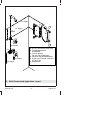
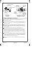
3. Install the Valve - Bath/Shower Application
NOTE: For installations that use a bath diverter spout and a
showerhead, install a twin ell (K-9663) between the valve and the
spout.
Install the valve on the support framing so the ″UP″ mark on the
valve is facing downward.
If the hot water supply is connected to the cold inlet, the cap
assembly must be rotated 180° to ensure proper orientation; see
the enlarged view showing the cap rotated 180°.
Install elbows and adapters (if needed) to 3/4″ copper tubing of
the proper length. Apply thread sealant, and connect the piping
to the bath and shower outlets of the valve.
This feature faces downward
for bath/shower installation.
To
Showerhead
Cold Inlet
Cold
Supply
Hot
Inlet
10"
(25.4 cm)
To Spout
Twin
Ell
Hot
Supply
1150733-2-A 6 Kohler Co.

4. Back-to-Back Valve Installation
Install both valves following the valve installation instructions.
The supplies to one of the valves will be reversed.
Remove the plaster guard, cap, cap assembly, and collar from the
valve from the valve with the reversed supply connections.
Rotate the cap assembly and collar 180° (tab on bottom).
Reassemble and securely tighten the screws on the cap assembly.
Reinstall the plaster guard.
This feature faces downward
for back-to-back installation.
Cold Supply 1"
Copper Tube
Hot Supply 1"
Copper Tube
180˚
Screws
Plaster Guard
Cap
Assembly
Kohler Co. 7 1150733-2-A

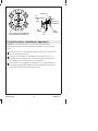
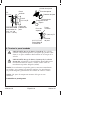
5. Multi-Showerhead Application Layout
F
E
A
D
C
B
1/2" Supply
1/2" Supply
1/2"
Supply
3/4" Supply
3/4" Supply
3/4" Supply
A.
B.
C.
D.
E.
F.
K-2971 HiFlow Rite-Temp Valve
Fixed Showerhead or
Handshower
Vacuum Breaker
(for use with Handshower)
Pressure Loop with Bodysprays
K-405 3-way Transfer Valve and
K-T9474 Trim
Showerhead
1150733-2-A 8 Kohler Co.

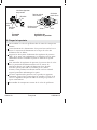
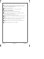
6. Flush the Piping
Disassemble the valve as shown to remove the internal
components.
Slowly open the water supplies to run water through the supply
piping and valve body to remove any debris.
Inspect the two inlet seals of the pressure balancing unit (PBU). If
the seals are damaged, replace them with the provided extra inlet
seals. Lubricate the seals using the capsule provided.
To reinstall the PBU, push it into the valve in the initial install
position with the nuts on the PBU toward the hot inlet. Make
sure the PBU seals do not come in contact with the inlet/outlet
holes during initial installation because their rough edges may
damage the seals.
Rotate the PBU counterclockwise while applying downward
pressure until it is seated in the seating indents on the bottom of
the valve. The PBU should not rotate when it is properly seated.
Reassemble the remaining valve components as shown.
PBU InstallationValve Assembly
Pressure
Balancing Unit
PBU
Valve
Valve Cap
Valve
Stop
Stop
Cover
Screw
Screw
Water
Outlet Hole
Initial Install
Position
Final Install
Position
Kohler Co. 9 1150733-2-A

7. Installation Checkout
Install caps to the temporary bath and shower nipples.
Turn on the hot and cold water supplies, and check the new
installation for leaks.
Remove the caps from the temporary nipples.
Remove the plaster guard.
Turn the valve stem to the ″On″ position, and cycle the control
through its operating range. Check for leaks.
For bath and shower installations, check the diverter system from
spout to showerhead.
Turn the valve off.
If the valve has stops, rotate both stop adjustments fully
clockwise.
Turn the valve on and verify that water does not run.
Turn the valve off and rotate both stop adjustments fully
counterclockwise.
Reinstall the plaster guard.
Rotate stops
1/4 turn.
1150733-2-A 10 Kohler Co.

8. Complete the Finished Wall
CAUTION: Risk of product damage. This valve contains
plastic and rubber components that may become damaged if
soldering heat is applied directly to the valve body.
CAUTION: Risk of damage to the K-2971-KS valve
assembly. When using the K-2971-KS HiFlow Valve in a
fiberglass or acrylic installation, use the Thin Wall Installation
Kit (88526).
NOTE: Thick wall installations are typically tile, plaster, marble, or
similar materials. Thin wall installations are typically fiberglass and
acrylic.
NOTE: Do not adjust the maximum water temperature at this time.
Thick Wall Installation
Provide a 5-9/16″ (14.1 cm) diameter hole in the wall material.
The flat front surface of the plaster guard must be flush with the
finished wall.
Complete the finished wall.
Plaster Guard
Dome
Finished
Wall
5-9/16" D.
(14.1 cm)
1/2"
(1.3 cm)
2-1/4" to 3"
(5.7 to 7.6 cm)
Rough-In Depth
Attachment Hole
Backing Plate
Backing Plate
Plaster Guard
Outer Ring
Valve Stem
Dome
Finished
Wall
Plaster
Guard
2-1/4" (5.7 cm)
Rough-In Depth
4" D. (10.2 cm)
Kohler Co. 11 1150733-2-A

Complete the Finished Wall (cont.)
Do not remove the plaster guard until instructed.
Thin Wall Installation
Remove the plaster guard from the backing plate.
Twist the plaster guard dome to separate it from the outer ring.
Discard the outer ring.
Slide the dome over the valve stem.
Provide a 4″ (10.2 cm) diameter hole in the wall material.
Make openings for the stops (if included) by using the holes in
the backing plate as a guide.
Secure the backing plate to the back of the wall material.
Do not remove the dome until instructed to do so.
1150733-2-A 12 Kohler Co.

9. Water Temperature Adjustment
CAUTION: Risk of personal injury. To eliminate the risk of
scalding, the water temperature should never be set above
120°F (49°C).
NOTE: Do not remove the O-ring and collar at this time. Removing
the O-ring and collar will change the factory setting for the
maximum water temperature.
Turn the valve clockwise to the full open position and let the hot
water run for several minutes. Position a thermometer in the
water stream and check the temperature.
For minor water temperature changes, adjust the setscrew, and
recheck the water temperature.
For major water temperature changes, remove the O-ring and
collar from the valve stem. Slowly rotate the valve stem until the
desired maximum water temperature is reached.
Reinstall the collar on the valve stem with the setscrew against
the side of the tab.
Reinstall the O-ring, rotate the valve stem counterclockwise to
shut the water off.
Recheck the water temperature.
Install the valve trim according to the instructions packed with
the product.
Complete the information on the valve label (if supplied).
Setscrew
O-Ring
O-Ring
Tab
Valve
Stem
Valve
Label
Collar
Kohler Co. 13 1150733-2-A
Page is loading ...
Page is loading ...
Page is loading ...
Page is loading ...
Page is loading ...
Page is loading ...
Page is loading ...
Page is loading ...
Page is loading ...
Page is loading ...
Page is loading ...
Page is loading ...
Page is loading ...
Page is loading ...
Page is loading ...
Page is loading ...
Page is loading ...
Page is loading ...
Page is loading ...
Page is loading ...
Page is loading ...
Page is loading ...
Page is loading ...
Page is loading ...
Page is loading ...
Page is loading ...
Page is loading ...
-
 1
1
-
 2
2
-
 3
3
-
 4
4
-
 5
5
-
 6
6
-
 7
7
-
 8
8
-
 9
9
-
 10
10
-
 11
11
-
 12
12
-
 13
13
-
 14
14
-
 15
15
-
 16
16
-
 17
17
-
 18
18
-
 19
19
-
 20
20
-
 21
21
-
 22
22
-
 23
23
-
 24
24
-
 25
25
-
 26
26
-
 27
27
-
 28
28
-
 29
29
-
 30
30
-
 31
31
-
 32
32
-
 33
33
-
 34
34
-
 35
35
-
 36
36
-
 37
37
-
 38
38
-
 39
39
-
 40
40


Kohler K-2971-KS-NA Installation guide
- Category
- Storage chests & cabinets & trunks
- Type
- Installation guide
Ask a question and I''ll find the answer in the document
Finding information in a document is now easier with AI
in other languages
- français: Kohler K-2971-KS-NA Guide d'installation
- español: Kohler K-2971-KS-NA Guía de instalación
Related papers
-
Kohler K-T9492-4-CP Installation guide
-
-
Kohler K-4645-RA-7 Installation guide
-
-
-
Kohler K-T130-3D-CP Installation guide
-
-
-
-
Other documents
-
Caroma 2284848 Installation guide
-
Danfoss AM-PBU 25 Operating instructions
-
 BK PRODUCTS 229-023 Installation guide
-
-
Thermasol 15-1010-MB Installation guide
-
Signature Hardware SH449137 Installation guide
-
-
Toto RENESSE TSKT Installation guide
-
-
GROHE 29903000 Installation guide
