Page is loading ...

Dell EMC PowerEdge XE7100
Installation and Service Manual
Regulatory Model: B22S Series, B24S Series
Regulatory Type: B22S001, B24S001
August 2020
Rev. A00

Notes, cautions, and warnings
NOTE: A NOTE indicates important information that helps you make better use of your product.
CAUTION: A CAUTION indicates either potential damage to hardware or loss of data and tells you how to avoid
the problem.
WARNING: A WARNING indicates a potential for property damage, personal injury, or death.
© 2020 Dell Inc. or its subsidiaries. All rights reserved. Dell, EMC, and other trademarks are trademarks of Dell Inc. or its subsidiaries. Other
trademarks may be trademarks of their respective owners.

Chapter 1: About this document.................................................................................................... 6
Chapter 2: PowerEdge XE7100 system overview............................................................................7
Supported configurations.................................................................................................................................................. 7
Front view of the System..................................................................................................................................................9
Front view of the control panel........................................................................................................................................9
Rear view of the system.................................................................................................................................................. 10
Inside the enclosure...........................................................................................................................................................10
Locating the service Tag of your system.....................................................................................................................12
System information label..................................................................................................................................................13
Rail sizing and rack compatibility matrix.......................................................................................................................18
Chapter 3: Initial system setup and configuration........................................................................20
Setting up the system......................................................................................................................................................20
iDRAC configuration......................................................................................................................................................... 20
Options to set up iDRAC IP address.......................................................................................................................20
Options to log in to iDRAC.........................................................................................................................................21
Resources to install operating system......................................................................................................................... 22
Options to download firmware ................................................................................................................................22
Options to download and install OS drivers .........................................................................................................22
Downloading drivers and firmware..........................................................................................................................23
Chapter 4: Installing and removing enclosure components...........................................................24
Safety instructions............................................................................................................................................................24
Before working inside your system...............................................................................................................................25
After working inside your system..................................................................................................................................25
Recommended tools......................................................................................................................................................... 25
Dell EMC PowerEdge XE7440 and XE7420 sleds..................................................................................................... 25
Removing the sled.......................................................................................................................................................25
Installing the sled.........................................................................................................................................................26
Power supply units............................................................................................................................................................ 27
Fault tolerant redundancy..........................................................................................................................................27
Removing a power supply unit................................................................................................................................. 28
Installing a power supply unit....................................................................................................................................28
Cooling fans .......................................................................................................................................................................29
Removing a cooling fan..............................................................................................................................................29
Installing a cooling fan................................................................................................................................................30
Removing the cooling fan cage.................................................................................................................................31
Installing the cooling fan cage.................................................................................................................................. 32
Removing the cooling fan board.............................................................................................................................. 33
Installing the cooling fan board................................................................................................................................ 34
Expander module...............................................................................................................................................................36
Removing the expander module.............................................................................................................................. 36
Installing the expander module.................................................................................................................................36
Contents
Contents 3

Removing the expander board................................................................................................................................. 37
Installing the expander board................................................................................................................................... 39
System cover..................................................................................................................................................................... 40
Removing the front system cover...........................................................................................................................40
Installing the front system cover..............................................................................................................................41
Removing the rear system cover.............................................................................................................................42
Installing the rear system cover...............................................................................................................................43
Removing the system cover..................................................................................................................................... 43
Installing the system cover....................................................................................................................................... 44
Drives................................................................................................................................................................................... 45
Removing a drive carrier............................................................................................................................................45
Installing a drive carrier..............................................................................................................................................46
Removing the drive from the drive carrier............................................................................................................48
Installing the drive into the drive carrier................................................................................................................49
Removing a 2.5-inch drive blank............................................................................................................................. 50
Installing a 2.5-inch drive blank................................................................................................................................ 51
Power distribution board..................................................................................................................................................51
Removing the power distribution board................................................................................................................. 51
Installing the power distribution board...................................................................................................................52
PERC.................................................................................................................................................................................... 54
Removing the PERC riser..........................................................................................................................................54
Installing the PERC riser............................................................................................................................................ 54
Removing the PERC card..........................................................................................................................................55
Installing the PERC card............................................................................................................................................56
Removing the PERC riser board.............................................................................................................................. 57
Installing the PERC riser board................................................................................................................................ 57
Drive cage........................................................................................................................................................................... 58
Removing the 3.5 inch drive cage...........................................................................................................................58
Installing the drive cage.............................................................................................................................................59
Backplanes and expander board....................................................................................................................................60
Backplane...................................................................................................................................................................... 60
3.5-inch hard drive mapping.....................................................................................................................................62
Removing the 2.5-inch hard drive backplane....................................................................................................... 63
Installing the backplane..............................................................................................................................................63
Removing the backplane/midplane assembly.......................................................................................................64
Installing the backplane/midplane assembly.........................................................................................................65
Intrusion switch module...................................................................................................................................................66
Removing the front intrusion switch...................................................................................................................... 66
Installing the intrusion switch................................................................................................................................... 67
Removing the rear intrusion switch........................................................................................................................68
Installing the rear intrusion switch.......................................................................................................................... 69
Chassis handle....................................................................................................................................................................70
Removing the handle.................................................................................................................................................. 70
Installing the handle..................................................................................................................................................... 71
Chapter 5: Technical specifications............................................................................................. 73
Dimensions of the PowerEdge XE7100........................................................................................................................73
Chassis weight................................................................................................................................................................... 74
PSU specifications............................................................................................................................................................ 74
Cooling specifications.......................................................................................................................................................74
4
Contents

Power distribution board................................................................................................................................................. 76
Drives and storage specifications..................................................................................................................................76
Expander module............................................................................................................................................................... 77
Environmental specifications.......................................................................................................................................... 77
Standard operating temperature specifications...................................................................................................77
Expanded operating temperature specifications ................................................................................................ 78
Particulate and gaseous contamination specifications.......................................................................................79
Maximum vibration specifications........................................................................................................................... 79
Maximum shock specifications.................................................................................................................................79
Maximum altitude specifications............................................................................................................................. 80
Chapter 6: System diagnostics and indicator codes..................................................................... 81
Status LED indicators....................................................................................................................................................... 81
System health and system ID indicator codes............................................................................................................ 81
iDRAC Direct LED indicator codes................................................................................................................................82
NIC indicator codes.......................................................................................................................................................... 82
Power supply unit indicator codes................................................................................................................................ 83
Using system diagnostics................................................................................................................................................ 84
Dell Embedded System Diagnostics........................................................................................................................84
Chapter 7: Documentation resources...........................................................................................86
Chapter 8: Getting help...............................................................................................................88
Contacting Dell EMC........................................................................................................................................................ 88
Documentation feedback................................................................................................................................................ 88
Accessing system information by using QRL..............................................................................................................88
Quick Resource Locator for XE7100, XE7420 and XE7440 systems..............................................................89
Receiving automated support with SupportAssist ...................................................................................................89
Recycling or End-of-Life service information.............................................................................................................89
Contents
5

About this document
This document provides an overview about the system, information about installing and replacing components, technical
specifications, diagnostic tools, and guidelines to be followed while installing certain components.
1
6 About this document

PowerEdge XE7100 system overview
The PowerEdgeXE7100 is an ultradense 5U enclosure that supports up to two independent two-socket (2S) sleds and 100 x
3.5-inch drives. The PowerEdge XE7100 enclosure supports the following:
● Up to two server sleds and up to two expander modules
● Six rear accessible system fans
● Two 2400 W redundant power supply units
● Up to 16 DDR4 RDIMM/LRDIMM with maximum capacity up to 2048 GB per sled
● Up to 100 x 3.5-inch SAS or SATA drives
● Up to 8 x 7 mm SATA SSD (4 supported for NVMe SSD)
NOTE: For more information about how to hot swap NVMe PCIe SSD U.2 device, see the Dell Express Flash NVMe
PCIe SSD User's Guide at https://www.dell.com/support> Browse all Products > Data Center Infrastructure >
Storage Adapters & Controllers > Dell PowerEdge Express Flash NVMe PCIe SSD > Documentation >
Manuals and Documents.
NOTE: All instances of SAS, SATA drives are seen as drives in this document, unless specified otherwise.
For more information about supported drives, see the Drive specifications section.
Topics:
• Supported configurations
• Front view of the System
• Front view of the control panel
• Rear view of the system
• Inside the enclosure
• Locating the service Tag of your system
• System information label
• Rail sizing and rack compatibility matrix
Supported configurations
The PowerEdge XE7100 chassis is available in two versions:
● PowerEdge XE7100 chassis with two XE7420 sleds:
2
PowerEdge XE7100 system overview 7

Figure 1. PowerEdge XE chassis with XE7420 sleds
● PowerEdge XE7100 chassis with XE7440 sled:
Figure 2. PowerEdge XE chassis with XE7440 sled
8
PowerEdge XE7100 system overview

Front view of the System
Figure 3. Front view of XE7100
1. Control panel 2. Expander module 1
3. Expander module 2 4. Service tag
Figure 4. Front view of expander module
1.
PERC slot 2. 2.5-inch SSDs
3. Pull out lever 4. Captive screw
Front view of the control panel
Figure 5. Front view of the control panel
PowerEdge XE7100 system overview
9

Rear view of the system
Figure 6. Rear view of the XE7100 system with HW sleds
1. Cooling fan 2. Power supply unit 1
3. Power supply unit 2 4. Half-width sled 2
5. Half-width sled 1
Figure 7. Rear view of the system with FW sled
1. Cooling fan
2. Power supply unit 1
3. Power supply unit 2
4. Full-width sled
Inside the enclosure
CAUTION: This system must be operated with the system cover installed to ensure proper cooling.
10 PowerEdge XE7100 system overview

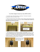
Figure 8. Inside the PowerEdge XE7100 enclosure
1. Hard drive cage 2. Plastic handle
3. Hard drive backplane and midplane assembly board 4. Rear intrusion switch
5. Power distribution board module / Chassis manager board
module
6. Fan cage
7. 3.5-inch HDD slot 8. Front intrusion switch
Figure 9. Inside the PowerEdge XE7440 sled
1.
Sled cable kit (1) 2. Motherboard bridge board (1)
3. Motherboard interposer board 4. Cooling fan
5. Memory sockets 6. Dust cover for processor 2
PowerEdge XE7100 system overview 11

7. System board 8. Heat sink for processor 1
9. Mini PERC card module 10. FH riser module
11. FE1 card 12. M.2 riser card
13. Cooling fan (For FE1 card) 14. Motherboard bridge board (2)
15. Sled cable kit (2)
Figure 10. Inside the PowerEdge XE7420 sled
1.
Sled cable kit 2. Cooling fans
3. Memory sockets 4. Heat sink for processor 1
5. System board 6. Heat sink for processor 2
7. Mini PERC card module 8. PCIe card module
9. M.2 riser card 10. Motherboard interposer board
11. Motherboard bridge board
Locating the service Tag of your system
Your system is identified by a unique Express Service Code and Service Tag number. The Express Service Code and Service Tag
are found on the front of the enclosure by pulling out the EST tag. This information is used by Dell to route support calls to the
appropriate personnel.
Figure 11. Locating the Service Tag of your system
1.
Information tag (top view) 2. Express Service Tag label
3. Information tag (bottom view) 4. Network MAC address information label
5. iDRAC MAC address information label
12 PowerEdge XE7100 system overview

System information label
Express service tag
Figure 12. Express service tag
PowerEdge XE7100 system overview
13

Service information
Figure 13. Service information
14
PowerEdge XE7100 system overview

Service information on the rear
Figure 14. Service information on the rear
PowerEdge XE7100 system overview
15

Configuration and layout
Figure 15. Configuration and layout
16
PowerEdge XE7100 system overview

System touchpoints
Figure 16. System touchpoints
PowerEdge XE7100 system overview
17

Jumper settings
Figure 17. Jumper settings
System tasks
Figure 18. System tasks
Rail sizing and rack compatibility matrix
For specific information about the rail solutions compatible with your system, see the Dell EMC Enterprise Systems Rail Sizing
and Rack Compatibility Matrix available at https://i.dell.com/sites/csdocuments/Business_solutions_engineering-
Docs_Documents/en/rail-rack-matrix.pdf.
The document provides the information that is listed below:
● Specific details about rail types and their functionalities
● Rail adjustability ranges for various rack mounting flange types
● Rail depth with and without cable management accessories
● Rack types that are supported for various rack mounting flange types
18
PowerEdge XE7100 system overview


Initial system setup and configuration
This section describes the tasks for initial setup and configuration of the Dell EMC system. The sections provide general steps
that you must complete to set up the system and the reference guides for detailed information.
Topics:
• Setting up the system
• iDRAC configuration
• Resources to install operating system
Setting up the system
Perform the following steps to set up the system:
Steps
1. Unpack the system.
2. Install the system into the rack. For more information see the rail installation and cable management accessory guides
relevant to your rail and cable management solution at www.dell.com/xemanuals.
3. Connect the peripherals to the system and the system to the electrical outlet.
4. Power on the system by pressing the power button.
For more information about setting up the system, see the Getting Started Guide that is shipped with your system.
iDRAC configuration
The Integrated Dell Remote Access Controller (iDRAC) is designed to make you more productive as a system administrator and
improve the overall availability of Dell EMC servers. iDRAC alerts you to system issues, helps you to perform remote
management, and reduces the need for physical access to the system.
Options to set up iDRAC IP address
To enable communication between your system and iDRAC, you must first configure the network settings based on your
network infrastructure. The network settings option is set to DHCP, by default.
NOTE: For static IP configuration, you must request for the setting at the time of purchase.
You can set up the iDRAC IP address using one of the following interfaces. For information about how to set up iDRAC IP
address, see the documentation links provided in the table.
Table 1. Interfaces to set up iDRAC IP address
Interface Documentation links
iDRAC Settings utility Integrated Dell Remote Access Controller User's Guide at
https://www.dell.com/idracmanuals or for system specific
Integrated Dell Remote Access Controller User's Guide, go to
https://www.dell.com/poweredgemanuals > Product
Support page of your system > Manuals & documents.
NOTE: To determine the most recent iDRAC release for
your platform and for latest documentation version, see
KB article https://www.dell.com/support/article/
sln308699.
3
20 Initial system setup and configuration
/