Page is loading ...

OPERATING INSTRUCTIONS
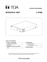
REMOTE CONTROLLER C-RM500
A B C D
WIPER
ZOOM
TELE
WIDE
FOCUS
FAR
NEAR
LENS SPEED
UP
DOWN
RIGHTLEFT
LOW HIGH
DEF AUX AUTO
E F G H
SELECT
MENU
GROUP
CH
SEQUENCE
FUNCTION
ALARM
RESET HOLD
AF POSITION CONTROLFREEZE FULL
REMOTE CONTROLLER C-RM500
1 2 3
4 5 6
7 8 9
C
0
SET
Please follow the instructions in this manual to obtain the optimum results from this unit.
We also recommend that you keep this manual handy for future reference.

2
TABLE OF CONTENTS
1. SAFETY PRECAUTIONS .................................................................................... 4
2. GENERAL DESCRIPTION .................................................................................. 5
3. FUNCTIONS ............................................................................................................ 5
4. NOMENClATURE AND FUNCTIONS
Top ............................................................................................................................... 6
Rear .............................................................................................................................. 8
Bottom (Function indications for the rear parts) ........................................................... 8
5. OPERATION
5.1. Operating the Camera
5.1.1. Selecting cameras for operation .................................................................. 9
5.1.2. Rotating the camera with the joystick ........................................................ 10
5.1.3. Activating the wiper ................................................................................... 10
5.1.4. Activating the defroster .............................................................................. 10
5.1.5. Controlling an auxiliary contact .................................................................. 10
5.1.6. Activating the automatic functions ............................................................. 11
5.1.7. Activating the zoom function ..................................................................... 11
5.1.8. Activating the focus function ...................................................................... 11
5.1.9. Changing the lens speed ........................................................................... 12
5.1.10. Activating the auto-focus function .............................................................. 12
5.1.11. Selecting the camera position ................................................................... 12
5.2. Monitor Display
5.2.1. Displaying the camera number
(only active when the Multi-Switcher is connected) ....................................13
5.2.2. Viewing the freeze screen
(only active when the Multi-Switcher is connected) ................................... 14
5.2.3. Using the Function keys ............................................................................ 15
5.2.4. Using the abbreviated numbers ................................................................ 15
5.2.5. Viewing full-screen displays ...................................................................... 16
5.2.6. Viewing multi-screen displays
(only active when the Multi-Switcher is connected)
[16-segment split-screen viewing] ............................................................. 16
[10-segment split-screen viewing] ............................................................. 17
[9-segment split-screen viewing] ............................................................... 17
[4-segment split-screen viewing] ............................................................... 18
5.2.7. Viewing sequential displays
[Sequential full-screen viewing] ................................................................. 19
[Sequential 4-segment split-screen viewing] ............................................. 19
5.3. Alarm Hold and Reset
5.3.1. Holding the alarm ...................................................................................... 20
5.3.2. Displaying alarm-activated camera images ............................................... 20
5.3.3. Resetting the alarm ................................................................................... 20

3
6. SETTINGS
6.1. Setting Items and Their Descriptions ................................................................... 21
6.2. Operating Keys and Display Screen .................................................................... 22
6.3. Basic Setting Operations ..................................................................................... 23
6.4. Setting the Functions
6.4.1. Operation mode ......................................................................................... 24
6.4.2. Switchers ................................................................................................... 25
6.4.3. Contact ...................................................................................................... 26
6.4.4. Automatic reset .......................................................................................... 27
6.4.5. Home position ............................................................................................ 28
6.4.6. I/O speed ................................................................................................... 29
6.4.7. Buzzer ....................................................................................................... 30
6.4.8. Initial screen .............................................................................................. 30
6.4.9. Channel designation .................................................................................. 31
6.4.10. Sensor alarm ............................................................................................. 32
6.4.11. Camera alarm ............................................................................................ 32
6.4.12. Camera check ........................................................................................... 33
6.4.13. Camera alarm preset ................................................................................. 34
6.4.14. Alarm signal ............................................................................................... 35
6.4.15. Alarm time ................................................................................................. 35
6.4.16. Alarm function ............................................................................................ 36
6.4.17. Alarm hold ................................................................................................. 36
6.4.18. Function key programming ........................................................................ 37
6.4.19. Abbreviation ............................................................................................... 38
6.4.20. Tour sequence ........................................................................................... 39
6.4.21. Camera menu ............................................................................................ 40
6.4.22. Password ................................................................................................... 40
7. CONNECTIONS
7.1. System Examples ................................................................................................ 41
7.2. Connection to Combination Cameras .................................................................. 43
7.3. Connection to the Multi-Switcher's RS-232C Terminal ....................................... 44
7.4. Connection to the Smart Switcher's RS-232C Terminal ...................................... 46
7.5. Connection When Controlling the System from 2 Locations ............................... 48
7.6. Alarm Output/Control Input Terminal Connections
7.6.1. Pin functions .............................................................................................. 49
7.6.2. Assembling D-sub connectors onto cables ............................................... 50
8. SPECIFICATIONS ................................................................................................ 51
Accessories ................................................................................................................ 51
Underwriters Laboratories Inc. (UL) has not tested the performance or reliability of the security aspects
of this product. UL has only tested for fire, shock or casualties as outlined in UL's Standard(s) for
Safety. UL Certification does not cover the performance or reliability of the security hardware and
security operating software. UL MAKES NO REPRESENTATIONS, WARRANTIES OR
CERTIFICATIONS WHATSOEVER REGARDING THE PERFORMANCE OR RELIABILITY OF ANY
SECURITY RELATED FUNCTIONS OF THIS PRODUCT.

4
1. SAFETY PRECAUTIONS
• Be sure to read the instructions in this section carefully before use.
• Make sure to observe the instructions in this manual as the conventions of safety symbols and messages
regarded as very important precautions are included.
• We also recommend you keep this instruction manual handy for future reference.
Do not expose the unit to rain or an environment where it may be
splashed by water or other liquids, as doing so may result in fire or
electric shock.
WARNING
Indicates a potentially hazardous situation which, if mishandled, could
result in death or serious personal injury.
WARNING
• Use the unit only with the voltage specified on the unit. Using a voltage higher than that which is specified
may result in fire or electric shock.
• Do not cut, kink, otherwise damage nor modify the power supply cord. In addition, avoid using the power
cord in close proximity to heaters, and never place heavy objects -- including the unit itself -- on the power
cord, as doing so may result in fire or electric shock.
• Avoid installing or mounting the unit in unstable locations, such as on a rickety table or a slanted surface.
Doing so may result in the unit falling down and causing personal injury and/or property damage.
• Should the following irregularity be found during use, immediately stop the power supply to the unit and
contact your nearest TOA dealer. Make no further attempt to operate the unit in this condition as this may
cause fire or electric shock.
· If you detect smoke or a strange smell coming from the unit.
· If water or any metallic object gets into the unit
· If the unit falls, or the unit case breaks
· If the power supply cord is damaged (exposure of the core, disconnection, etc.)
· If it is malfunctioning (no tone sounds.)
· If it is malfunctioning (no image appears.)
• To prevent a fire or electric shock, never open nor remove the unit case as there are high voltage
components inside the unit. Refer all servicing to your nearest TOA dealer.
• Do not touch a power plug during thunder and lightning, as this may result in electric shock.
• Do not place cups, bowls, or other containers of liquid or metallic objects on top of the unit. If they
accidentally spill into the unit, this may cause a fire or electric shock.
Indicates a potentially hazardous situation which, if mishandled, could
result in moderate or minor personal injury, and/or property damage.
CAUTION
• Never plug in nor remove the power supply plug with wet hands, as doing so may cause electric shock.
• When unplugging the power supply cord, be sure to grasp the power supply plug; never pull on the cord
itself. Operating the unit with a damaged power supply cord may cause a fire or electric shock.
•When moving the unit, be sure to remove its power supply cord from the wall outlet. Moving the unit with the
power cord connected to the outlet may cause damage to the power cord, resulting in fire or electric shock.
When removing the power cord, be sure to hold its plug to pull.
• Avoid installing the unit in humid or dusty locations, in locations exposed to the direct sunlight, near the
heaters, or in locations generating sooty smoke or steam as doing otherwise may result in fire or electric
shock.
• Do not place heavy objects on the unit as this may cause it to fall or break which may result in personal
injury and/or property damage. In addition, the object itself may fall off and cause injury and/or damage.
• Contact your TOA dealer as to the cleaning. If dust is allowed to accumulate in the unit over a long period of
time, a fire or damage to the unit may result.
• If dust accumulates on the power supply plug or in the wall AC outlet, a fire may result. Clean it periodically.
In addition, insert the plug in the wall outlet securely.
• Disconnect the power supply cord for safety purposes when cleaning or leaving the unit unused for 10 days
or more. Doing otherwise may cause a fire or electric shock.

• The explanations in this manual assume that the C-RM500 Remote Controller is connected to a
C-MS160D/S or C-MS90D/S Multi-Switcher and the C-SS8 Smart Switcher.
• Camera number: Refers to the camera input terminal number connected to the switcher.
• Position number: Combination camera orientation can be programmed for No. 1 – 255.
5
2. GENERAL DESCRIPTION
The TOA C-RM500 Remote Controller is used to remotely control TOA's Combination cameras over
communication lines (RS-485). It can remotely control video image switching and cameras in combination with
TOA's Multi-Switcher or Smart Switcher.
3. FUNCTIONS
• Display Selection
The following screen formats can be selected for display of camera images connected to the Multi-Switcher:
full screen, 4-segment, sequential 4-segment, 9-segment, 10-segment or 16-segment split-screen and
sequential full-screen.
• Manual Operation
Controls the Combination camera's zoom, focus, pan and tilt functions.
• Camera Position Selection
Controls the Combination camera's orientation, and displays the camera image on the monitor in the
selected orientation.
• Function Key Programming
Camera numbers or camera number/position combinations can be programmed into the function keys (A –
H). Pressing the function key displays the camera image on the full screen. If position numbers have been
set, images of the selected camera orientation can be displayed.
• Abbreviated Number Display
Permits camera numbers or camera number/position combinations to be programmed for numbers 1 – 512.
Entering the programmed number followed by the SET key displays the corresponding camera number on
the full screen, and the image of selected camera orientation if the position number has been set.
•Alarm Function
Controls the display in synchronization with alarm signals received from a camera. When an alarm signal is
detected, the image of the corresponding camera takes display precedence. The C-RM500 Controller also
features an Alarm Hold function that temporarily disables channel (camera number) switching in response to
an alarm signal. This prevents the display from being forcibly switched to an alerted camera during close
inspection (when the Multi-Switcher is connected).
Equipment Which Can Be Controlled with the C-RM500
Shown below are equipment that can be controlled with the C-RM500.
Camera: C-CC501, C-CC504, C-CC551, and C-CC554
Up to 31 cameras can be connected to the unit's Camera control terminal and controlled. The use
of the C-IF500 Interface Unit will increase the number to up to 64 cameras (when the C-SS8
switcher is in use). Note that the cameras cannot be controlled if their number is greater than the
number of inputs of a connected switcher.
Switcher: C-MS90D, C-MS90S, C-MS160D, C-MS160S, and C-SS8
Only one switcher can be connected for remote camera control. However, as to the C-SS8, 1
master-designated unit and up to 7 slave-designated units can be connected to remotely control
the cameras.
About the Camera Control Terminal
The Camera control terminal is used to connect the C-CC501, C-CC504, C-CC551, or C-CC554 Combination
Camera or the C-IF500 Interface Unit. Up to 31 pieces of equipment can be connected to the terminal.
About the Descriptions in This Manual

6
4. NOMENCLATURE AND FUNCTIONS
[Top]
A B C D
WIPER
ZOOM
TELE
WIDE
FOCUS
FAR
NEAR
LENS SPEED
UP
DOWN
RIGHTLEFT
LOW HIGH
DEF AUX AUTO
E F G H
SELECT
MENU
GROUP
CH
SEQUENCE
FUNCTION
ALARM
RESET HOLD
AF POSITION CONTROLFREEZE FULL
WIPER DEF AUX AUTO AF POSITION CONTROLFREEZE FULL
REMOTE CONTROLLER C-RM500
1 2 3
4 5 6
7 8 9
C
0
SET
1 2 3 4 5 6 7 8 9 10
21
22 23
24
25
26
27 28 29
11 12 13
14 15 16
18 19
17
20
Notes
Depending on the system configuration, the operation of some keys may be disabled. The corresponding keys
are marked with the following indications.
*
1
Does not function in systems using only with Combination cameras.
*
2
Does not function in systems using the Smart Switcher.
*
3
Functions only when connected to the Combination camera.
*
4
Connect the DC power supply of 12 V/over 150 mA to either input terminal.
1. Function keys [A – H]
A single depression of one of these keys displays
the full-screen image of the key's corresponding
camera number and position number. Each key
can also be set to activate automatic operations
(panning, tracing, and sequential switching) of the
selected Combination camera.
2. Alarm reset key / Alarm indicator
Resets the system's Alarm mode. The indicator
light flashes during Alarm operation.
3. Alarm hold key / Hold indicator
Places activated Alarm inputs on hold. The
indicator light flashes during Alarm Hold.
4. 16-segment split-screen key *
1
, *
2
Displays camera images in the 16-segment split-
screen format.
5. 10-segment split-screen key *
1
, *
2
Displays camera images in the 10-segment split-
screen format. Subsequent depressions of this
key can toggle between two separate groups of
10-segment split-screen displays.
6. 9-segment split-screen key *
1
, *
2
Displays camera images in the 9-segment split-
screen format. Subsequent depressions of this key
can toggle between two separate groups of 9-
segment split-screen displays.

7
7. 4-segment split-screen key *
1
, *
2
Displays camera images in the 4-segment split-
screen format. Subsequent depressions of this
key can cycle through 4 separate groups of 4-
segment split-screen displays.
8. Sequential 4-segment split-screen key *
1
Sequentially cycles through all connected
camera outputs of up to 4 groups of cameras at
a preset time interval. Program sequencing and
viewing intervals are set at the Smart Switcher
when connected.
9. Group selector key *
1
, *
2
Switches on-screen camera groups during 4-, 9-
or 10-segment split-screen display.
10. Sequence key *
1
, *
2
Sequences all connected camera outputs to the
full screen at the specified time interval. (Viewing
intervals are set at the switcher.)
11. CH call key *
1
, *
2
Displays the camera number on the monitor for a
preset period of time. This key is convenient for
finding the camera number when no indication or
only the camera name is displayed.
12. Menu key
Displays the menu on the Remote Controller's
LCD screen for setting functions. To enable,
press lightly with a pointed object. When the
menu is opened and the desired item is selected,
the screen under the setting will be displayed.
Pressing the key again will close the setting
screen and the display will disappear.
13. LCD screen
Displays character information for the setting
menu, numeric keypad input status, current
operation, etc.
14. Zoom key *
3
Sets the Combination camera's zoom lens for
"TELESCOPE" or "WIDE ANGLE" operation.
The Zoom key can only be used while the
Control indicator is on.
15. Focus key *
3
Sets the Combination camera's zoom lens for
"FAR" or "NEAR" operation. The Focus key can
only be used while the Control indicator is on.
16. Lens speed key / Indicator *
3
Adjusts the speed of lens operation when the
Zoom or Focus key is pressed.
17. Joystick *
3
Controls the attached pan/tilt head's horizontal
and vertical movement. The joystick can only be
used while the Control indicator is on.
18. Numeric keypad [0 – 9]
Used to enter the camera number, position
number, abbreviated number, etc.
19. Clear key [C]
Used to correct entry errors. Also, turns off the
buzzer when sounded by an activated alarm.
20. SET key
Used in conjunction with the numeric keypad to
program the camera number or position number.
Also, if pressed after entering the set abbreviated
number with the numeric key, the camera image
corresponding to that number can be displayed
on the monitor.
21. Wiper key *
3
Remotely controls the outdoor-use Combination
camera's wiper. This key can only be used while
the Control indicator is on.
22. Defroster key/Indicator *
3
Remotely controls the outdoor-use Combination
camera's defroster. This key can only be used
while the Control indicator is on.
23. Auxiliary contact key / Indicator *
3
Controls (makes or breaks) the Combination
camera's Auxiliary Contact Output 1. The
indicator is on when auxiliary contact is at make,
and off when the contact is at break. This key
can only be used when the Control indicator is
on.
24. Auto key / Indicator *
3
Enables or disables the Combination camera's
automatic functions (Auto-Pan, Auto-Trace, and
Preset Sequence). The Auto key can only be
used when the Control indicator is on.
• Auto-Pan
Automatically pans a camera pan/tilt head.
• Auto-Trace
Automatically executes manual camera
operations stored in memory.
• Preset Sequence
Automatically sequences camera positions in
the order of preset position numbers.
25. Auto-focus key / Indicator *
3
Enables the Combination camera's Auto-Focus
function. This key can only be used when the
Control indicator is on.
26. Freeze screen key / Indicator *
1
, *
2
Freezes camera images. However, sequential
displays cannot be made still. The indicator
flashes when there is a freeze image on the
screen.

8
27. Position key
Orients the Combination camera toward the set
direction. The Position key can only be used
when the Control indicator is on. Pressing the
Position key without designating the position
number orients the camera toward the direction
programmed under Position No. 1 (Home
position).
28. Control key *
2
/ Indicator
Used to designate the camera to be manually
controlled during a multi-screen display. This key
cannot be used during a full-screen or sequential
display. Also, nothing is operated even if this key is
pressed without designating the channel number.
The indicator lights when the camera is controllable.
29. Full-screen key
Displays the designated camera output on the full
screen. This key cannot be used unless the camera
number is entered.
SWITCHER
SWITCHER REMOTECAMERA
GND GND GND GND GND
DC IN
12V
REMOTE CONTROLLER
model C-RM500 120
TOA Corporation
MADE IN JAPAN
ALARM IN ALARM OUT
DC IN 12V
30
31
32
33
34
35
36
37
38
12V 150mA Class2
39
[Rear]
[Bottom]
(Function indications for the rear parts)
30. Camera control terminal (RS-485)
Connects to the Combination camera.
31. Switcher control terminal (RS-485)
Connects to the Multi-Switcher's dedicated
remote control terminal, and controls the
Switcher's screen display.
32. Slave unit remote control terminal
Connects to another C-RM500 Remote
Controller to be designated as a slave unit for
remote control from different locations.
33. Power input terminal [DC IN 12 V] *
4
Used to supply power from a source other than
the supplied AC adapter.
34.Ground Terminal [GND]
Please ground by the cable that attached the
supplied clamp filter.
(Please attach a clamp filter to the nearest
possible position of this controller.)
35. Switcher control terminal (RS-232C)
Connects to the RS-232C I/O terminal of the
Multi-Switcher and Smart Switcher to control
these switchers.
36. Alarm input terminal (RS-232C)
Connects to an alarm input unit to receive alarm
signals. This terminal is also a serial I/O terminal
that functions as an interface with external
systems.
37. Alarm output / Control input terminal
Makes contact corresponding to the alarm-
activated channel (camera number).
38. AC adapter power input terminal [DC IN 12 V] *
4
Insert the DC plug of the dedicated AC adapter
into this terminal.
39. Rating label
1turn
GND
GND
Te rminal
clamp filter

9
5. OPERATION
5.1. Operating the Camera
The following camera operations can be performed when the Control indicator is on.
[Operating keys]
WIPER
ZOOM
TELE
WIDE
FOCUS
FAR
NEAR
LENS SPEED
UP
DOWN
RIGHTLEFT
LOW HIGH
DEF AUX AUTO AF POSITION CONTROLFREEZE FULL
REMOTE CONTROLLER C-RM500
1 2 3
4 5 6
7 8 9
C
0
SET
Wiper key
Zoom key Focus key Lens speed key
Defroster key
Auxiliary key
Auto key
Full-screen key
Control key
Position key
Auto-focus key
Joystick Numeric keypad
5.1.1. Selecting cameras for operation
Cameras to be manually controlled can be selected during full-screen or multi-segment screen display.
(Refer to p. 10 – 12 for individual camera operations.)
Step 1. Using the numerical keypad, press the
desired camera number.
Step 2. Press either the Full-Screen key or
Control key.
2-1. Operation in full-screen display
format
Press the Full-Screen key.
The Control indicator will light,
permitting operation of the designated
camera.
2-2. Operation in multi-screen display
format
Press the Control key during multi-
screen display.
The Control indicator will light,
permitting operation of the designated
camera.
Note
Both XX and YY camera images can be freely
set using the switch.
LCD screen
13 CHANNEL
FULL CONTROL
Lights
LCD screen
13 CONTROL
Monitor screen
(10-segment split-screen display)
09 10 11 12
13 14 15 16
YYXX
Camera name
This camera can be operated.
CONTROL CONTROL
Lights
1 3
(Example)

5.1.2. Rotating the camera with the joystick
Any connected Combination camera can be rotated in the desired direction using a joystick.
With the camera selected, tilt the joystick in the direction in which the camera is to be rotated.
The camera will rotate in the direction the joystick was tilted.
(Example)
When panning the camera to the right.
5.1.3. Activating the wiper
When a Combination camera with built-in wiper is connected to the system, the wiper can be activated using
the Wiper key.
Press the Wiper key while the camera is selected.
The camera's built-in wiper is activated while the key is
held down.
5.1.4. Activating the defroster
When a Combination camera with built-in defroster is connected to the system, the defroster can be activated
using the Defroster key.
Step 1. Press the Defroster key while the
camera is selected.
The defroster indicator will light and
the camera's built-in defroster will be
activated.
Step 2. Press the Defroster key again.
The defroster indicator will extinguish
and the defroster will stop.
5.1.5. Controlling an auxiliary contact
The Combination camera's Auxiliary Contact Output 1 can be switched ON and OFF.
Step 1. Press the Auxiliary key while the
camera is selected.
The Auxiliary indicator will light and the
auxiliary contact is switched ON.
Step 2. Press the Auxiliary key again.
The Auxiliary indicator will extinguish
and the auxiliary contact is switched
OFF.
10
LCD screen
M ANUAL
LCD screen
DEFROSTER
UP
DOWN
RIGHTLEFT
Joystick
DEF DEF
Lights
LCD screen
WIPER
WIPER
DEF DEF
Lighting
LCD screen
AUX I L I ARY SW
AUX AUX
Lights
AUX AUX

5.1.6. Activating the automatic functions
When a Combination camera is connected to the system, its automatic functions can be enabled using the
Auto key.
Step 1. Press the Auto key while the camera
is selected. The camera's automatic
functions (Auto-Pan*
1
, Auto Trace*
2
,
or Preset Sequence*
3
) will begin to
operate.
Set the automatic functions to be enabled on the Camera Menu. (Refer to p. 40.)
*
1
The camera's automatic panning function.
*
2
Automatic repetition of manual camera operations that have been stored in memory.
*
3
Automatic sequential display of camera positions in the order that their position numbers were
selected.
Step 2. Press the Auto key again.
The Auto indicator extinguishes and
automatic operations are stopped.
5.1.7. Activating the zoom function
When a Combination camera is connected, its zoom lens can be activated using the Zoom key.
Press the Zoom ("Telescope" or "Wide Angle") key while
the camera is selected. Zooming continues as long as the
key is pressed.
5.1.8. Activating the focus function
When a Combination camera is connected, its image can be focused using the Focus key.
Press the Focus ("Far" or "Near") key while the camera is
selected. Focusing continues as long as the key is
pressed.
11
LCD screen
AUTO
AUTO AUTO
Lights
AUTO AUTO
Lights
LCD screen
MANUAL
ZOOM
TELE
WIDE
LCD screen
MANUAL
FOCUS
FAR
NEAR

5.1.11. Selecting the camera position
Step 1. Enter the camera position number with the
numeric keypad.
Step 2. Press the Position key.
The camera image corresponding to the selected
position will be displayed on the monitor.
Note
When the Trace function is used in the camera setting, the selection of Position No. 255 executes Auto-Trace
operations.
12
LCD screen
AUTO FOCUS
AF AF
Lightis
AF
Auto-focus operation is completed.
LENS SPEED
LOW HIGH
LENS SPEED
LOW HIGH
LENS SPEED
LOW HIGH
LENS SPEED
LOW HIGH
Lights
LCD screen
5POSITION
POSITION
5
(Example)
5.1.9. Changing the lens speed
The speed of lens movement when the Zoom or Focus key is pressed can be adjusted in 4 steps of operation:
1) Very slow, 2) Slow, 3) Moderately fast, 4) Fast.
Step 1. Press the Lens Speed key.
The speed indicator number increases by one each time the Speed key is depressed to indicate that
the lens speed has been increased by one level. (Lens operating speed returns to "Very slow" when
the Speed key is pressed while in Fast mode.)
Step 2. Repeat Step 1. until the desired speed is displayed.
5.1.10. Activating the auto-focus function
When a Combination camera is connected, the Auto-Focus function can be activated with a press of the Auto-
Focus key.
Press the Auto-Focus key while the camera is
selected.
The indicator remains lit while the Auto-Focus
function is in operation.

5.2.1. Displaying the camera number (only active when the Multi-Switcher is connected)
Step 1. Press the Channel Call key while a camera image
is displayed on the monitor.
All connected camera numbers will be displayed.
Note
The camera number is displayed even when the
camera is not connected.
[When confirming the camera number and operating its display]
Step 2. Enter the camera number with the numeric
keypad.
Step 3. Press either the Full Screen or Freeze Screen
key.
The camera image will be displayed in full-screen
or freeze-screen format.
13
5.2. Monitor Display
[Operation keys]
A B C D
WIPER
ZOOM
TELE
WIDE
FOCUS
FAR
NEAR
LENS SPEED
UP
DOWN
RIGHTLEFT
LOW HIGH
DEF AUX AUTO
E F G H
SELECT
MENU
GROUP
CH
SEQUENCE
FUNCTION
ALARM
RESET HOLD
AF POSITION CONTROLFREEZE FULL
REMOTE CONTROLLER C-RM500
1 2 3
4 5 6
7 8 9
C
0
SET
Function key
Alarm reset key
Alarm hold key
16-segment split-screen key
4-segment split-screen key
Sequential 4-segment split-screen key
9-segment split-screen key
Sequential key
Group selector key
CH call key
Numeric keypad
SET key
10-segment split-screen key
Freeze key Control key Full-screen key
LCD screen
CHA N N E L C A L L
CH
Monitor screen
(10-segment split-screen display)
01
05
02 03 04
06 07 08
1612

5.2.2. Viewing the freeze screen (only active when the Multi-Switcher is connected)
Step 1. Enter the camera number to
freeze using the numeric
keypad.
Step 2. Press the Freeze Screen key.
The "F" indication will flash on
the corresponding camera
image screen.
Step 3. Repeat Steps 1 and 2 to freeze
other camera images.
Note
In a system using the RS-232C to
control the Multi-Switcher, the freeze
screen display is only possible when the
full-screen mode is selected.
[Simultaneously resetting all freeze displays]
Press the Freeze Screen key.
[Resetting individual freeze displays]
Step 1. Enter the camera number to reset the
freeze display using the numeric
keypad.
Step 2. Press the Freeze Screen key.
14
LCD screen
13 FREEZE
FREEZE FREEZE
Flashes
Monitor screen
(10-segment split-screen display)
09 10 11 12
F141516
FREEZE
XX
Camera name
Freeze display indication
Note: Two lower screens can be freely
set using the switcher.
1 3
(Example)
LCD screen
FREEZE FREEZE
Monitor screen
(10-segment split-screen display)
09 10 11 12
13 14 15 16
XX
The freeze display will be reset.
FREEZE
LCD screen
FREEZE FREEZE
Monitor screen
(10-segment split-screen display)
09 10 11 12
13 14 15 16
YYXX
1 3
(Example)

5.2.4. Using the abbreviated numbers
By merely pressing the abbreviated number followed by the SET key, the camera image (camera number and
position number) programmed under the abbreviated number can be displayed on the monitor.
(Refer to p. 38 "Abbreviation.")
Step 1. Enter the abbreviated number with the
numeric keypad.
Step 2. Press the SET key.
The programmed camera position's
image will be displayed on the full
screen. Simultaneously, the Control
indicator lights, permitting camera
operations with the joystick.
15
A B C D E F G H
FUNCTION
LCD screen
DFUNCT I ON KEY
01
CONTROL
Lights
Display of the camera number programmed
into the Function key.
LCD screen
25 SET
01
Display of the camera number programmed
under the abbreviated number.
CONTROL
SET
Lights
2 5
5.2.3. Using the Function keys
By simply pressing a Function key (A – H), the camera image (camera number and position number)
programmed into the key can be displayed on the monitor. (Refer to p. 37 "Function key programming.")
Press a Function key (A – H).
The corresponding camera image (camera number and position number) is displayed on the full screen of the
monitor.

5.2.5. Viewing full-screen displays
Step 1. Enter the camera number to be
displayed on the full screen using the
numeric keypad.
Step 2. Press the Full Screen key.
The designated camera image will be
displayed on the full screen.
Simultaneously, the Control indicator
lights, permitting camera operations
with the joystick.
5.2.6. Viewing multi-screen displays (only active when the Multi-Switcher is connected)
[16-segment split-screen viewing]
Press the 16-Segment Split-Screen key.
All connected camera images will be displayed on the monitor.
16
LCD screen
13 CHANNEL
13
Camera number displayed
in full-screen format
CONTROLFULL
Lights
1 3
(Example)
LCD screen
16–SEGMENT
Monitor screen
01 02 03 04
0605 07 08
09 10 11 12
1413 15 16
Camera number

[10-segment split-screen viewing]
Step 1. Press the 10-Segment Split-Screen key.
The images of camera numbers 1 – 8 (Group 1)
and 2 more images (set with the Switcher) will
be displayed on the monitor.
Step 2. Press the 10-Segment Split-Screen key
again, or the Group Selector key.
The images of camera numbers 9 – 16
(Group 2) and 2 more images (set with
the Switcher) will be displayed on the
monitor.
[9-segment split-screen viewing]
Step 1. Press the 9-Segment Split-Screen key.
The images of camera numbers 1 – 9 (Group 1)
will be displayed on the monitor.
Step 2. Press the 9-Segment Split-Screen key
again, or the Group Selector key.
The images of camera numbers 10 – 16
(Group 2) will be displayed on the
monitor.
17
LCD screen
10–SEGMENT
GROUP
SELECT
or
Monitor screen (Group 1)
01 02 03 04
0605 07 08
YYXX
Camera name
Camera number
Monitor screen (Group 2)
09 10 11 12
1413 15 16
YYXX
LCD screen
9–SEGMENT
GROUP
SELECT
or
Monitor screen (Group 1)
01 02 03
04 05 06
07 08 09
Camera number
Monitor screen (Group 2)
10 11 12
13 14 15
16
Note: Camera images can be freely selected for
Screens XX and YY using the switcher.

[4-segment split-screen viewing]
Step 1. Press the 4-Segment Split-Screen key.
The images of camera numbers 1 – 4 (Group 1)
will be displayed on the monitor.
Step 2. Press the 4-Segment Split-Screen
key again, or the Group Selector key.
The images of camera numbers 5 – 8
(Group 2) will be displayed on the
monitor.
Step 3. Repeat Step 2 to display other
succeeding the images of camera
numbers. The displayed camera
group is switched to Group 3
(Cameras 9 – 12), Group 4 (Cameras
13 – 16) and then back to Group 1
each time the 4-Segment Split-
Screen key is pressed.
18
LCD screen
4–SEGMENT
GROUP
SELECT
or
Monitor screen (Group 1)
0403
0201
Camera number
Monitor screen (Group 2)
0807
0605
GROUP
SELECT
or
Monitor screen (Group 3)
1211
1009

5.2.7. Viewing sequential displays
The outputs of all cameras connected to the switcher can be displayed on the monitor in sequential order at
viewing intervals preset at the switcher. For details, refer to the instruction manual included with the switcher.
[Sequential full-screen viewing]
Press the Sequence key. The
images for Cameras 1 – 16 are
displayed in sequential order.
Note that if the Tour Sequence
function has been set, the
camera images will be switched
in the order of the specified
reproduction number. Refer to
p. 39 "Tour sequence.")
Note
In this example, Camera No. 2 is not
displayed on the monitor because it is
not connected.
[Sequential 4-segment split-screen viewing]
Press the sequential 4-
Segment Split-Screen key.
Tip
The Program Sequence
function is made operational
when the Smart Switcher is
connected. For details, refer to
the instruction manual included
with the Smart Switcher.
19
LCD screen
SEQUENCE
SEQUENCE
Monitor screen
Camera No. 1
Camera name
Camera No. 16
Camera name
Camera No. 3
Camera name
LCD screen
4–SEG SEQ
DDDDCCCC
BBBBAAAA
HHHHGGGG
FFFFEEEE
PPPP OOOO
NNNNMMMM
LLLLKKKK
JJJJIIII
Camera name
Monitor screen
Group 1 Group 2
Group 3Group 4

20
5.3. Alarm Hold and Reset
The Alarm can be held or reset when "1. KEY" has been selected in the "Alarm Hold" setting, and is not
activated when "2. ALWAYS" has been selected. (Refer to p. 36 "Alarm hold.")
5.3.1. Holding the alarm
Press the Alarm Hold key.
The Alarm Hold indicator light will flash.
5.3.3. Resetting the alarm
Press the Alarm Reset key.
The Alarm Reset indicator light will extinguish, resetting the alarm state.
Note
The alarm cannot be reset when "2. LEVEL" has been selected in the Alarm Signal setting. The state of alarm
continues as long as an alarm signal input is received. (Refer to p. 35 "Alarm signal.")
5.3.2. Displaying alarm-activated camera images
Press the Alarm Hold key.
The Alarm Hold indicator light will extinguish, displaying the alerted camera image on the monitor in full-
screen format.
[When an alarm signal is received during Alarm Hold]
The Alarm Reset indicator light flashes while the "AL HOLD" indication is displayed on the monitor.
LCD screen
ALARM HOLD
Flashes
RESET HOLD RESET HOLD
Monitor screen
ALARM
RESET HOLD RESET HOLD
Monitor screen
0403
0201
RESET HOLD RESET HOLD
Monitor screen
(4-segment split-screen display)
AL HOLD
03
02
04
01
Flashes
RESET HOLD RESET HOLD
/