Page is loading ...

ST.RE.E10141.5
Issue 5
ENGLISH (UK)
REFERENCE GUIDE
TT1280 and TT1282 High Definition
Professional Receiver/Decoder
Software Version 2.0.0 (and later)
TT1280 and TT1282 HD Professional Receiver/Decoder

Preliminary Pages
Page ii Reference Guide: TT128x High Definition Professional Receiver/Decoder
ST.RE.E10141.5
Issue 5 first published in 2005 by:
T
ANDBERG TELEVISION LTD
R
EGISTERED ADDRESS:
U
NIT 2 STRATEGIC PARK, COMINES WAY,
H
EDGE END, SOUTHAMPTON,
H
AMPSHIRE,
SO30 4DA
U
NITED KINGDOM
Re
g
istered Com
p
an
y
Number 03695535
This document and the information contained in it is the property o
f
TANDBERG Television Ltd and may be the subject of patents
pending and granted. It must not be used for commercial purposes
nor copied, disclosed, reproduced, stored in a retrieval system o
r
transmitted in any form or by any means (electronic, mechanical,
photocopying, recording or otherwise), whether in whole or in part,
without TANDBERG Television’s prior written agreement.
2003 - 2005 TANDBERG Television Ltd. All rights reserved.
SVENSKA
LÄS DETTA FÖRST!
Om Ni inte förstår informationen i denna handbok
ARBETA DÅ INTE MED DENNA UTRUSTNING.
En översättning till detta språk av denna handbok kan också anskaffas,
på Er bekostnad.
ENGLISH (UK)
READ THIS FIRST!
If you do not understand the contents of this manual
DO NOT OPERATE THIS EQUIPMENT.
Also, translation into any EC official language of this manual can be
made available, at your cost.
ΕΛΛΗΝΙΚΑ
∆ΙΑΒΑΣΤΕ ΠΡΩΤΑ ΑΥΤΟ!
Αν δεν καταλάβετε το περιεχόµενο αυτού του βοηθήµατος/εγχειριδίου
ΜΗΝ ΛΕΙΤΟΥΡΓΗΣΕΤΕ ΑΥΤΟΝ ΤΟΝ ΕΞΟΠΛΙΣΜΟ.
Επίσης, αυτό το εγχειρίδιο είναι διαθέσιµο σε µετάφραση
σε αυτή τη γλώσσα και µπορείτε να το αγοράσετε.
DEUTSCH
LESEN SIE ZUERST DIESEN HINWEIS!
Sollte Ihnen der Inhalf dieses Handbuches nicht klar verständlich sein,
dann
BEDIENEN SIE DIESE GERÄTE NICHT!
Eine Übersetzung des Handbuches in diese Sprache ist gegen
Berechnun
g
lieferbar.
ESPAÑOL
LEA ESTE AVISO PRIMERO!
Si no entiende el contenido de este manual
NO OPERE ESTE EQUIPO.
Podemos asimismo suministrarle una traducción de este manual al
(idioma) previo pago de una cantidad adicional que deberá abonar
usted mismo.
FRANÇAIS
AVANT TOUT, LISEZ CE QUI SUIT!
Si vous ne comprenez pas les instructions contenues dans ce manuel
NE FAITES PAS FONCTIONNER CET APPAREIL.
En outre, nous pouvons vous proposer, à vos frais, une version
française de ce manuel.
ITALIANO
LEGGERE QUESTO AVVISO PER PRIMO!
Se non si capisce il contenuto del presente manuale
NON UTILIZZARE L’APPARECCHIATURA.
È anche disponibile la versione italiana di questo manuale, ma il costo è
a carico dell’utente.
PORTUGUÊS
LEIA O TEXTO ABAIXO ANTES DE MAIS NADA!
Se não compreende o texto deste manual
NÃO UTILIZE O EQUIPAMENTO.
O utilizador poderá também obter uma tradução do manual para o
português à própria custa.
NEDERLANDS
LEES DIT EERST!
Als u de inhoud van deze handleiding niet begrijpt
STEL DEZE APPARATUUR DAN NIET IN WERKING.
U kunt tevens, op eigen kosten, een vertaling van deze handleiding
krijgen.
DANSK
LÆS DETTE FØRST!
Udstyret må ikke betjenes
MEDMINDRE DE TIL FULDE FORSTÅR INDHOLDET AF DENNE
HÅNDBOG.
Vi kan også for Deres regning levere en dansk oversættelse af denne
håndbog.
SUOMI
LUE ENNEN KÄYTTÖÄ!
Jos et ymmärrä käsikirjan sisältöä
ÄLÄ KÄYTÄ LAITETTA.
Käsikirja voidaan myös suomentaa asiakkaan kustannuksella.

Preliminary Pages
Reference Guide: TT128x High Definition Professional Receiver/Decoder Page iii
ST.RE.E10141.5
List of Contents
Chapter 1: Introduction
This chapter identifies the equipment versions covered by this manual;
describes the purpose of the equipment in a typical system; provides a
summary of its main features; identifies the controls, indicators and
connectors.
Chapter 2: Installing the Equipment
This chapter provides a guide to the suitability of an installation; gives
detailed procedures for the preparation, installation and configuration of
the equipment including important safety information; provides pin-out
details of the external connectors; and details the power-up/-down
procedures.
Chapter 3: Operating the Equipment Locally
This chapter provides a guide to using the Front Panel LCD interface and
details the setting-up, configuration and operating procedures.
Chapter 4: Operating the Equipment Remotely
This chapter provides a guide to configuring and preparing the unit for
remote operation.
Chapter 5: Alarms
This chapter provides a guide to configuring the alarm interface.
Chapter 6: Options
This chapter describes the available hardware and software options for the
IRD.
Chapter 7: Preventive Maintenance and Fault-finding
This chapter details routine maintenance tasks to be performed; provides
general servicing advice, and information regarding warranty and
maintenance; provides general fault-finding information for other types of
problem which may be encountered.
Annex A: Glossary
Annex B: Technical Specification
Annex C: Menus
Annex D: Language Abbreviations
Annex E: Factory Defaults

Preliminary Pages
Page iv Reference Guide: TT128x High Definition Professional Receiver/Decoder
ST.RE.E10141.5
About This Reference Guide
This Reference Guide provides instructions and information for the
installation and operation of the TT1280 and TT1282 1U digital integrated
Receiver/Decoder (IRD).
This Reference Guide should be kept in a safe place for reference for the
life of the equipment. It is not intended that this Reference Guide will be
amended by the issue of individual pages. Any revision will be by a
complete reissue. Further copies of this Reference Guide can be ordered
from the address shown on page vii. If passing the equipment to a third
party, also pass the relevant documentation.
Issues of this manual are listed below:
Issue Date Software Version Comments
1 Oct 2003 1.0.0 Initial release.
2 Jan 2004 1.1.5 -48 V version added. IP Input card, RAS and RAS 2 added.
3 Feb 2004 2.0.0
TT1282 added. DTS, Closed Captions, RS-422 data, frame sync and
Ethernet HSD added.
4 May 2004 2.0.0 HOM option card added
5 Mar 2006 2.0.0 Inclusion of DVB-S2 information
The following documents are also associated with this equipment:
• ST.US.E10141: User Guide
General
All best endeavours have been made to acknowledge registered
trademarks and trademarks used throughout this Reference Guide. Any
notified omissions will be rectified in the next issue of this Reference
Guide. Some trademarks may be registered in some jurisdictions but not
in others.
Registered trademarks and trademarks used are acknowledged below and
marked with their respective symbols. However, they are not marked
within the text of this Reference Guide.
Registered Trademarks
Ethernet
®
is a registered trademark of Xerox Corporation.
VideoGuard
®
is a registered trademark of NDS Limited.
Dolby Digital
®
and AC-3
®
are registered trademarks of Dolby Laboratories
Licensing Corporation
.
Trademarks
Alteia
™
is a trademark of TANDBERG Television Limited.
Macrovision
This product incorporates copyright protection technology that is protected
by U.S. patents and other intellectual property rights. Use of this copyright
protection technology must be authorized by Macrovision Corporation, and
is intended for home and other limited viewing uses only unless authorized
by Macrovision. Reverse engineering or disassembly is prohibited.

Preliminary Pages
Reference Guide: TT128x High Definition Professional Receiver/Decoder Page v
ST.RE.E10141.5
Warnings, Cautions and Notes.
Heed Warnings
All warnings on the product and in the operating instructions should be
adhered to. The manufacturer can not be held responsible for injuries or
damage where warnings and cautions have been ignored or taken lightly.
Read Instructions
All the safety and operating instructions should be read before this product
is operated.
Follow Instructions
All operating and use instructions should be followed.
Retain Instructions
The safety and operating instructions should be retained for future
reference.
WARNINGS...
WARNINGS GIVE INFORMATION WHICH, IF STRICTLY OBSERVED, WILL PREVENT PERSONAL
INJURY OR DEATH, OR DAMAGE TO PERSONAL PROPERTY OR THE ENVIRONMENT. THEY
ARE BOXED AND SHADED FOR EMPHASIS, AS IN THIS EXAMPLE, AND ARE PLACED
IMMEDIATELY PRECEDING THE POINT AT WHICH THE READER REQUIRES THEM.
CAUTIONS...
Cautions give information which, if strictly followed, will prevent damage to equipment or other goods.
They are boxed for emphasis, as in this example, and are placed immediately preceding the point at
which the reader requires them.
NOTES...
Notes provide supplementary information. They are highlighted for emphasis, as in this example, and
are placed immediately after the relevant text.
EMC Compliance
This equipment is certified to the EMC requirements detailed in Annex B,
Technical Specification. To maintain this certification, only use the leads
supplied or, if in doubt, contact Customer Services.

Preliminary Pages
Page vi Reference Guide: TT128x High Definition Professional Receiver/Decoder
ST.RE.E10141.5
Contact Information
TANDBERG Television Customer Services
Support Services
Our primary objective is to provide first class customer care that is tailored
to your specific business and operational requirements. All levels are
supported by one or more service performance reviews to ensure the
perfect partnership between TANDBERG Television and your business.
Warranty
All TANDBERG Products and Systems are designed and built to the highest
standards and are covered under a comprehensive 12 month warranty.
Levels of Continuing TANDBERG Television Service Support
For stand-alone equipment, then TANDBERG Television
BASIC Advantage is the value for money choice for you. BASIC provides
you with year-by-year Service long after the warranty has expired.
For systems support you can choose either Gold or Silver Advantage.
These packages are designed to save you costs and protect your income
through enlisting the help of TANDBERG Television support specialists.
VOYAGER Advantage is the truly mobile service solution. This provides a
package specifically designed to keep you mobile and operational.
Call TANDBERG Sales for more details.
Where to Find Us
Europe, Middle East +44 (0) 23 8048 4455
and Africa: Fax: +44 (0) 23 8048 4467
Americas: +888 671 1268 (US and Canada)
+678 812 6255 (Outside of mainland US)
China: +86 10 6856 0260 (Beijing)
+852 2530 3215 (Hong Kong)
Australia/NZ: +612 9360 2053
Internet Address: http://www.tandbergtv.com

Preliminary Pages
Reference Guide: TT128x High Definition Professional Receiver/Decoder Page vii
ST.RE.E10141.5
Technical Training
Training Courses
TANDBERG Television provides a wide range of training courses on the
operation and maintenance of our products and on their supporting
technologies. TANDBERG can provide both regularly scheduled courses and
training tailored to individual needs. Courses can be run either at your
premises or at one of our dedicated training facilities.
Where to Find Us
For further information on TANDBERG Television's training programme
please contact us:
International Telephone: +44 23 8048 4229
International Facsimile +44 23 8048 4467
E-mail Address: [email protected]
Internet Address http://www.tandbergtv.com
Customer Services and Technical Training Postal Address
Tandberg Television
Unit 2
Strategic Park
Comines Way
Hedge End
Southampton
Hampshire
SO30 4DA
United Kingdom
Return of Equipment
If you need to return equipment for repair, please contact the Customer
Services Helpdesk on +44 (0) 23 8048 4455. A Returns Authorisation
Number (RAN) will be issued and full details of the unit will be logged.
Technical Publications
If you need to contact TANDBERG Television Technical Publications
regarding this publication, e-mail: techpub[email protected].

Preliminary Pages
Page viii Reference Guide: TT128x High Definition Professional Receiver/Decoder
ST.RE.E10141.5
BLANK

Reference Guide: TT128x High Definition Professional Receiver/Decoder Page 1-1
ST.RE.E10141.5
Chapter 1
1. 1Introduction
Contents
1.1 Scope of This Reference Guide................................ 1-3
1.1.1 Who Should Use This Reference Guide....... 1-3
1.1.2 What Equipment is Covered by This
Reference Guide .......................................... 1-3
The Equipment Models................................. 1-3
Software Version .......................................... 1-4
1.2 Summary of Features ............................................... 1-4
1.2.1 Main Features............................................... 1-4
1.2.2 Inputs............................................................ 1-5
ASI Input (Decoder)...................................... 1-5
SSI Input (Decoder)...................................... 1-5
Remote Control ............................................ 1-5
QPSK L-Band Inputs (Satellite Receivers)
(Option)......................................................... 1-5
BPSK/QPSK/8PSK/16QAM (HOM) L-
Band Inputs (Satellite Receivers) (Option) ... 1-6
TTV G.703 DS3 and E3 Input (Telco
Receivers) (Option) ...................................... 1-6
IP Input (Telco Receivers) (Option) .............. 1-6
Frame Synchronisation................................. 1-6
1.2.3 Outputs......................................................... 1-6
Transport Stream Outputs............................ 1-6
Video Outputs............................................... 1-6
Audio Outputs............................................... 1-6
Data Output .................................................. 1-6
Alarm Output ................................................ 1-6
1.3 The Satellite Receiver............................................... 1-7
1.3.1 Typical Satellite System................................ 1-7
1.3.2 Input Connections......................................... 1-7
1.3.3 What the Satellite Receiver Does................. 1-8
1.4 The Telco Receiver/Decoder .................................... 1-9
1.4.1 Typical Decoder System ...............................1-9
1.4.2 What the Decoder Does..............................1-10
1.5 Control Modes .........................................................1-10
1.5.1 Introduction .................................................1-10
1.5.2 Front Panel (Local) Modes..........................1-11
1.6 Guided Tour ............................................................1-11
1.6.1 Construction................................................1-11
1.6.2 Front Panel Controls ...................................1-11
1.6.3 Front Panel LEDs........................................1-12
1.6.4 Rear Panel ..................................................1-12
List of Figures
Figure 1.1: Front View of a Satellite Receiver ............................... 1-3
Figure 1.2: Typical Satellite Compression System ........................ 1-7
Figure 1.3: What the Satellite Receiver Does................................ 1-8
Figure 1.4: Typical Compression System...................................... 1-9
Figure 1.5: Role of the Decoder................................................... 1-10
Figure 1.6: Front Panel States..................................................... 1-11
Figure 1.7: Front Panel Controls.................................................. 1-12
List of Tables
Table 1.1: Equipment Model Descriptions..................................... 1-3

Introduction
Page 1-2 Reference Guide: TT128x High Definition Professional Receiver/Decoder
ST.RE.E10141.5
BLANK

Introduction
Reference Guide: TT128x High Definition Professional Receiver/Decoder Page 1-3
ST.RE.E10141.5
1.1 Scope of This Reference Guide
1.1.1 Who Should Use This Reference Guide
This Reference Guide is written for operators/users of the TT1280 and
TT1282 Integrated Receiver/Decoder (IRD). It describes the unit’s
functions and operation. The Reference Guide is written to assist in the
installation and day-to-day care and operation of the unit. Maintenance
information requiring the covers to be removed is not included.
The TT1280 and TT1282 are usually referred to throughout this Reference
Guide as ‘IRD(s)’ unless there is a specific difference, where they will be
referred to by the model number.
WARNING…
DO NOT REMOVE THE COVERS OF THIS EQUIPMENT. HAZARDOUS VOLTAGES ARE PRESENT
WITHIN THIS EQUIPMENT AND MAY BE EXPOSED IF THE COVERS ARE REMOVED. ONLY
TANDBERG TELEVISION TRAINED AND APPROVED SERVICE ENGINEERS ARE PERMITTED TO
SERVICE THIS EQUIPMENT.
CAUTION…
Unauthorised maintenance or the use of non-approved replacements may affect the equipment
specification and invalidate any warranties.
1.1.2 What Equipment is Covered by This Reference Guide
The Equipment Models
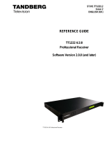
The IRD described in this Reference Guide is the base model.
Figure 1.1: Front View of a Satellite Receiver
Table 1.1: Equipment Model Descriptions
Model Number Marketing Code Description
TT1280 Common
Interface
TT1280/CIBAS MPEG-2 HD Decoder with integrated Common Interface CAM reader,
AC mains voltage input. MPEG 4:2:0 video decode only.
TT1280 Common
Interface
(-48 V version)
TT1280/CIBAS/48V MPEG-2 HD Decoder with integrated Common Interface CAM reader,
-48 Vdc voltage input. MPEG 4:2:0 video decode only.
TT1280 Director
(-48 V version)
TT1280/DIRBAS/48V MPEG-2 HD Decoder with integrated Director Smart Card Reader,
-48 Vdc voltage input. MPEG 4:2:0 video decode only.
TT1280 Director TT1280/DIRBAS MPEG-2 HD Decoder with integrated Director Smart Card Reader,
AC mains voltage input. MPEG 4:2:0 video decode only.
TT1282 Common
Interface
TT1282/CIBAS MPEG-2 HD Decoder with integrated Common Interface CAM reader,
AC mains voltage input. MPEG 4:2:0 and 4:2:2 video decode.
TT1282 Director
(-48 V version)
TT1282/DIRBAS/48V MPEG-2 HD Decoder with integrated Director Smart Card Reader,
-48 Vdc voltage input. MPEG 4:2:0 and 4:2:2 video decode.

Introduction
Page 1-4 Reference Guide: TT128x High Definition Professional Receiver/Decoder
ST.RE.E10141.5
Model Number Marketing Code Description
TT1282 Common
Interface
(-48 V version)
TT1282/CIBAS/48V MPEG-2 HD Decoder with integrated Common Interface CAM reader,
-48 Vdc voltage input. MPEG 4:2:0 and 4:2:2 video decode.
TT1282 Director TT1282/DIRBAS MPEG-2 HD Decoder with integrated Director Smart Card Reader,
AC mains voltage input. MPEG 4:2:0 and 4:2:2 video decode.
Software Version
This Reference Guide covers the functions of software version 2.0.0 and
later.
To verify the installed version access the Systems Menu (Menu 7.2.1).
The menus are described in Annex C, Menus.
1.2 Summary of Features
1.2.1 Main Features
The IRD is fully compliant with the appropriate sections of the MPEG-2
1
,
DVB-S
2
and DSNG
3
specifications and offers the following features:
• Front Panel Controls and Indications:
A vertical split two line x 40 character back-lit dot matrix LCD
display with pushbuttons for Up, Down, Left, Right, Edit, and
Save to provide information and operator choice entry.
LEDs to indicate lock and general alarm conditions.
• Service Selection:
Chosen from a menu list of available Services carried in the
currently received Transport Stream.
Up to 40 preselected choices can be stored within the unit.
• Multiple Inputs (Satellite Receivers):
L-band Satellite Receivers have two inputs (QPSK).
• TTV G.703 (DS3 and E3) Input (Telco Receivers).
• IP Input (Telco Receivers).
• Video Decoding:
MPEG 4:2:0 mode support.
MPEG 4:2:2 mode support (TT1282 only).
• Audio Decoding:
Sampling rates 32, 44.1, 48 kHz.
All MPEG-1 data rates.
All Dolby Digital AC-3 data rates, decoded as a Dolby Stereo
downmix.
Linear uncompressed audio, data rates as defined by SMPTE 302M.
1
Moving Pictures Expert Group: MPEG-2 specification ISO 13818.
2
European Digital Video Broadcasting (DVB) Project. EN 300 421 Digital broadcasting systems for television, sound
and data services: Framing structure, channel coding and modulation for the 11/12 GHz satellite service.
3
European Digital Video Broadcasting (DVB) Project : EN 301 210 Digital broadcasting systems for television, sound
and data services: Framing structure, channel coding and modulation for digital satellite news gathering (DSNG) and
other contribution applications by satellite.

Introduction
Reference Guide: TT128x High Definition Professional Receiver/Decoder Page 1-5
ST.RE.E10141.5
• Data:
DTS audio detection and pass-through.
Low Speed Data: RS-232 asynchronous (up to 38.4 kbit/s).
High Speed Data: Ethernet Data-piping (up to 5 Mbit/s) (option).
High Speed Data: RS-422 synchronous (up to 2048 kbit/s)
(option).
• Transport Stream Output:
ASI Transport Stream output with maximum data rate 160 Mbit/s.
• Remote Control:
SNMP.
RS-232 (Alteia protocol).
• Clock/Calendar:
Available to co-ordinate universal and local time.
Constantly updated when locked to a valid Transport Stream.
• Transport Stream Demultiplexing:
Maximum capability is 160 Mbit/s, depending on CA in use and
input front end.
• Video Decoding:
Maximum Video decoding capability of 50 Mbit/s.
• Audio:
Audio embedding in the digital video output (compressed AC-3 not
supported).
• VANC data support:
Closed Captions.
VITC.
• Frame Synchronisation of video output to a composite analogue input.
• Local Control Methods:
Front Panel User Interface.
1.2.2 Inputs
ASI Input (Decoder)
One BNC connector supporting both byte-mode and single packet burst
mode.
SSI Input (Decoder)
One BNC connector providing SMPTE 310M compliant input.
Remote Control
An RJ-45 Ethernet connector for connection to a PC or network switch to
provide SNMP control.
QPSK L-Band Inputs (Satellite Receivers) (Option)
Two F-type connectors connect the L-band output of a suitable LNB either
directly or via a suitable attenuator giving lightning and surge protection.

Introduction
Page 1-6 Reference Guide: TT128x High Definition Professional Receiver/Decoder
ST.RE.E10141.5
BPSK/QPSK/8PSK/16QAM (HOM) L-Band Inputs (Satellite
Receivers) (Option)
Four F-type connectors connect the L-band output of a suitable LNB either
directly or via a suitable attenuator giving lightning and surge protection.
DVB-S QPSK, DVB-S2 QPSK, 8PSK Input (Satellite
Receivers)(Option)
Four F-type connectors (TT1280/HWO/DVBS2) or Three F-type connectors
+ IF Inputs + Constellation output (TT1280/HWO/DVBS2/IF/CONST).
Connect the L-Band output of a suitable LNB either directly or via a
suitable attenuator giving lightning and surge protection.
TTV G.703 DS3 and E3 Input (Telco Receivers) (Option)
Equipped with a single BNC connector for receiving signals over a PDH
Telco network.
IP Input (Telco Receivers) (Option)
A single 10/100BaseT RJ-45 connector for receiving signals over Ethernet.
Frame Synchronisation
A BNC connector accepts a composite video input to which the video
output timing can be synchronised.
1.2.3 Outputs
Transport Stream Outputs
• Two BNC connectors output ASI Transport Streams with a maximum
data rate of 160 Mbit/s, depending on the CA in use and the input card
front-end.
Video Outputs
• One SVGA HD video output carried on a D-type connector.
• Two digital video outputs carried on BNC connectors.
Audio Outputs
• Two 9-way D-type, male connectors decode two PES streams of audio
from the Transport Stream. The audio outputs simultaneous analogue
and digital. The digital mode can be changed via the user interface.
Data Output
• RS-232 asynchronous low-speed data output carried on a 9-way,
D-type, female connector.
• RJ-45 high-speed data over Ethernet output (option).
• RS-422 synchronous high-speed data output carried on a 9-way
D-type, female connector.
Alarm Output
A 9-way, D-type connector for interfacing to the alarm and failure
monitoring within the equipment. This includes a summary alarm signal
that coincides with the general front-panel ALARM LED.

Introduction
Reference Guide: TT128x High Definition Professional Receiver/Decoder Page 1-7
ST.RE.E10141.5
There are five relays for failure monitoring (four alarms and one summary
alarm). The operator can define (using the Alarm Menu pages) which alarm
conditions drive the relays. This is described in Chapter 5, Alarms and
Annex C, Menus.
1.3 The Satellite Receiver
1.3.1 Typical Satellite System
The IRD Satellite Receivers are components of the MPEG-2/DVB compliant
range of TANDBERG Television equipment. They are designed for use by
broadcasters and distributors of video, audio and data Services over
satellite.
Figure 1.2: Typical Satellite Compression System
1.3.2 Input Connections
The Satellite Receiver interfaces directly to Low-Noise Block (LNB) and
accepts an intermediate frequency (IF) input in the band 950 - 2150 MHz
(L-band) for operation in the specified symbol-rate range (see Annex B,
Technical Specification). The unit can provide dc power and polarisation
switching to the LNB.
TANDBERG
MPEG-2
Transport
Stream
TANDBERG
1 2 3
4 5 6
7 8 9
0 * ±
evolution 5000
Multiplexer (Standby)
TANDBERG
1 2 3
4 5 6
7 8 9
0 * ±
evolution 5000
Multiplexer (Main)
TANDBERG
▲
◄ ►
▼
evolution 5000
Modulator (Main)
Local
Inputs
evolution 5000
Encoder
(
1
)
TANDBERG
1 2 3
4 5 6
7 8 9
0 * ±
TANDBERG
1 2 3
4 5 6
7 8 9
0 * ±
evolution 5000
Encoder
(
2
)
TANDBERG
1 2 3
4 5 6
7 8 9
0 * ±
evolution 5000
Encoder (n)
TANDBERG
▲
◄ ►
▼
evolution 5000
Modulator (Standby)
10BaseT
evolution 5000
Multiplex Element Manager
Ethernet Hub
Ethernet
Control
Ethernet
Control
Ethernet
Control
Ethernet
Control
Ethernet
Control
Ethernet
Ethernet
Ethernet
Up-converter
and HP
A
Transport Stream
Processor
TT1280/TT1282
TANDBERG

Introduction
Page 1-8 Reference Guide: TT128x High Definition Professional Receiver/Decoder
ST.RE.E10141.5
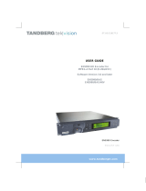
1.3.3 What the Satellite Receiver Does
The Receiver can be tuned to a specified satellite channel frequency and
polarisation. The input is down-converted via a Low-Noise Block (LNB) to
provide an L-band input to the Receiver. The front-end tuning is
microprocessor controlled with a frequency synthesised local oscillator. A
software tuning and acquisition algorithm resolves translation errors
(mainly due to the LNB).
The signal is then passed to a demodulator that recovers the signal using
soft-decision decoding. The resulting stream is Reed-Solomon decoded and
descrambled to provide inputs to the Decoder circuit. The received channel
may contain multiple Services, therefore the Receiver’s demultiplexer is
configured to select a single video Service and other audio/data
components and present them at the output.
Figure 1.3: What the Satellite Receiver Does
TT1280/TT1282 Satellite Receiver
f
n
f
n+1
f
n+2
f
n+3
f
n+4
horizontal
polarisation
vertical
polarisation
SHF
Low-Noise Block
L-band
Tune to a
satellite
channel
Select a
Service from
the satellite
channel
Multi
p
le satellite channels
Multi
p
le Services on the tuned satellite channel
Select the
components from
the chosen Service
Video
Audio
Data
Trans
p
ort Stream
Multi
p
le com
p
onents on the selected Service

Introduction
Reference Guide: TT128x High Definition Professional Receiver/Decoder Page 1-9
ST.RE.E10141.5
1.4 The Telco Receiver/Decoder
1.4.1 Typical Decoder System
The Decoder is a component of TANDBERG Television’s range of
equipment. It is designed for use by broadcasters and distributors of video
and audio Services. It can be used as a Transport Stream monitor or to
decode signals received over a telecommunications network.
Figure 1.4: Typical Compression System
MPEG-2
Transport
Stream
TANDBERG
1 2 3
4 5 6
7 8 9
0 * ±
evolution 5000
Multiplexer (Standby)
TANDBERG
1 2 3
4 5 6
7 8 9
0 * ±
evolution 5000
Multiplexer (Main)
Local
Inputs
evolution 5000
Encoder
(
1
)
TANDBERG
1 2 3
4 5 6
7 8 9
0 * ±
TANDBERG
1 2 3
4 5 6
7 8 9
0 * ±
evolution 5000
Encoder
(
2
)
TANDBERG
1 2 3
4 5 6
7 8 9
0 * ±
evolution 5000
Encoder
(
n
)
10BaseT
evolution 5000
Multiplex Element Manager
Ethernet Hub
Ethernet
Control
Ethernet
Control
Ethernet
Control
Ethernet
Ethernet
Ethernet
Transport Stream
Processor
TANDBERG
Network
Adapter Unit
TANDBERG
Network
Adapter Unit
Telecommunications
Network
TT1280/TT1282
Decoder
TANDBERG

Introduction
Page 1-10 Reference Guide: TT128x High Definition Professional Receiver/Decoder
ST.RE.E10141.5
1.4.2 What the Decoder Does
The ASI interface is used to present the Transport Stream in the format
required by the internal Decoder circuitry. At this point, the operation of
the unit is the same as the Satellite Receiver.
The Decoder can be used to receive an input signal from a Public Telecom
Network via a Network Adapter Unit (NAU). No error correction is
supported at the input of the unit so a level of Quality of Service should be
negotiated with the Telecom Network Provider.
The Decoder is configured to select a single video Service and other
audio/data components from the multiple Services on the incoming
Transport Stream and present them at the output.
Figure 1.5: Role of the Decoder
1.5 Control Modes
1.5.1 Introduction
The IRD is designed for unattended operation. Once set up, the unit
requires no further attention except to ensure the fan is working. There are
up to three control modes associated with the Receiver (dependent upon
options fitted). The unit remains in the chosen control mode until another
mode is requested.
NOTE…
Local (Front Panel) Control is the factory default if TANDBERG Director is not installed.
TANDBERG
TT1280/TT1282 Decoder
Select a Service from
the incoming Transport
Stream
Select the components
from the selected Service
Video
Audio
Data
Transport Stream
Multiple components on the selected Service
Incoming Transport Stream carried
over a telecommunications network
Multiple Services on the incoming Transport Stream
Network
Adapter Unit

Introduction
Reference Guide: TT128x High Definition Professional Receiver/Decoder Page 1-11
ST.RE.E10141.5
1.5.2 Front Panel (Local) Modes
Operating the IRD from the Front Panel is via two main operating modes:
Navigate and Edit. See Section 3.3, Front Panel Operating Modes.
Figure 1.6: Front Panel States
1.6 Guided Tour
1.6.1 Construction
The IRD is constructed using a screened self-ventilated modular system.
All operational inputs and outputs are via rear-panel connectors. The unit
may be operated freestanding or mounted in a 19-inch rack.
1.6.2 Front Panel Controls
The physical interface for the Front Panel consists of an alphanumeric LCD
display, pushbuttons, and status LEDs that are used to set up and monitor
the unit. The general layout is shown in Figure 1.7. Information on the use
of these controls is given in Chapter 3, Operating the Equipment Locally.
User input is via six pushbuttons comprising four cursor pushbuttons: Left,
Right, Up, and Down; and two edit control pushbuttons: Edit and Save.
Each pushbutton has an integral green LED except Save, which has an
integral red LED. When lit these LEDs indicate to the user which
pushbutton is currently active.
Automatic repeat following an initial delay period is implemented for the
Left, Right, Up, and Down pushbuttons in software.
EDIT
NAVIGATE
Timeout (5 minutes)
EDIT Off
EDIT On
SAVE

Introduction
Page 1-12 Reference Guide: TT128x High Definition Professional Receiver/Decoder
ST.RE.E10141.5
Figure 1.7: Front Panel Controls
1.6.3 Front Panel LEDs
Figure 1.7 shows the location of the LEDs on the front panel. The LEDs
indicate the equipment status as follows:
The red ALARM LED is used to indicate an IRD fault condition, e.g. a
missing or faulty input signal. It should be off for correct operation,
although it may be lit briefly during power-up.
The green LOCK LED is used to indicate that the IRD is locked to a
Transport Stream when lit, and indicates correct conditions and correct
system functioning.
1.6.4 Rear Panel
Inputs and outputs to the unit are taken via the rear panel. Connector
descriptions are given in Chapter 2, Installing the Equipment and
Chapter 6, Options.
LCD display
Save
Edit Up
Down
Left
Right
Alarm LED
Lock LED
/