Page is loading ...

ST.RE.E10152.2
Issue 2
ENGLISH (UK)
REFERENCE GUIDE
SM6610, SM6615, SM6620 and SM6625
Satellite Modulators
Software Version 2.0 and later
SM6610, SM6615, SM6620 and SM6625 Satellite Modulators

Preliminary Pages
Page ii Reference Guide: SM6610, SM6615, SM6620 and SM6625 Satellite Modulators
ST.RE.E10152.2
Issue 2 first published in 2005 by:
T
ANDBERG TELEVISION LTD
R
EGISTERED ADDRESS:
U
NIT 2 STRATEGIC PARK, COMINES WAY,
H
EDGE END, SOUTHAMPTON,
H
AMPSHIRE,
SO30 4DA
U
NITED KINGDOM
Registered Company Number 03695535
This document and the information contained in it is the property o
f
TANDBERG Television Ltd and may be the subject of patents
pending and granted. It must not be used for commercial purposes
nor copied, disclosed, reproduced, stored in a retrieval system o
r
transmitted in any form or by any means (electronic, mechanical,
photocopying, recording or otherwise), whether in whole or in part,
without TANDBERG Television’s prior written agreement.
2004 - 2005 TANDBERG Television Ltd. All rights reserved.
SVENSKA
LÄS DETTA FÖRST!
Om Ni inte förstår informationen i denna handbok
ARBETA DÅ INTE MED DENNA UTRUSTNING.
En översättning till detta språk av denna handbok kan också anskaffas,
på Er bekostnad.
ENGLISH (UK)
READ THIS FIRST!
If you do not understand the contents of this manual
DO NOT OPERATE THIS EQUIPMENT.
Also, translation into any EC official language of this manual can be
made available, at your cost.
ΕΛΛΗΝΙΚΑ
∆ΙΑΒΑΣΤΕ ΠΡΩΤΑ ΑΥΤΟ!
Αν δεν καταλάβετε το περιεχόµενο αυτού του βοηθήµατος/εγχειριδίου
ΜΗΝ ΛΕΙΤΟΥΡΓΗΣΕΤΕ ΑΥΤΟΝ ΤΟΝ ΕΞΟΠΛΙΣΜΟ.
Επίσης, αυτό το εγχειρίδιο είναι διαθέσιµο σε µετάφραση
σε αυτή τη γλώσσα και µπορείτε να το αγοράσετε.
DEUTSCH
LESEN SIE ZUERST DIESEN HINWEIS!
Sollte Ihnen der Inhalf dieses Handbuches nicht klar verständlich sein,
dann
BEDIENEN SIE DIESE GERÄTE NICHT!
Eine Übersetzung des Handbuches in diese Sprache ist gegen
Berechnun
g
lieferbar.
ESPAÑOL
LEA ESTE AVISO PRIMERO!
Si no entiende el contenido de este manual
NO OPERE ESTE EQUIPO.
Podemos asimismo suministrarle una traducción de este manual al
(idioma) previo pago de una cantidad adicional que deberá abonar
usted mismo.
FRANÇAIS
AVANT TOUT, LISEZ CE QUI SUIT!
Si vous ne comprenez pas les instructions contenues dans ce manuel
NE FAITES PAS FONCTIONNER CET APPAREIL.
En outre, nous pouvons vous proposer, à vos frais, une version
française de ce manuel.
ITALIANO
LEGGERE QUESTO AVVISO PER PRIMO!
Se non si capisce il contenuto del presente manuale
NON UTILIZZARE L’APPARECCHIATURA.
È anche disponibile la versione italiana di questo manuale, ma il costo è
a carico dell’utente.
PORTUGUÊS
LEIA O TEXTO ABAIXO ANTES DE MAIS NADA!
Se não compreende o texto deste manual
NÃO UTILIZE O EQUIPAMENTO.
O utilizador poderá também obter uma tradução do manual para o
português à própria custa.
NEDERLANDS
LEES DIT EERST!
Als u de inhoud van deze handleiding niet begrijpt
STEL DEZE APPARATUUR DAN NIET IN WERKING.
U kunt tevens, op eigen kosten, een vertaling van deze handleiding
krijgen.
DANSK
LÆS DETTE FØRST!
Udstyret må ikke betjenes
MEDMINDRE DE TIL FULDE FORSTÅR INDHOLDET AF DENNE
HÅNDBOG.
Vi kan også for Deres regning levere en dansk oversættelse af denne
håndbog.
SUOMI
LUE ENNEN KÄYTTÖÄ!
Jos et ymmärrä käsikirjan sisältöä
ÄLÄ KÄYTÄ LAITETTA.
Käsikirja voidaan myös suomentaa asiakkaan kustannuksella.

Preliminary Pages
Reference Guide: SM6610, SM6615, SM6620 and SM6625 Satellite Modulators Page iii
ST.RE.E10152.2
List of Contents
Chapter 1: Introduction
This chapter identifies the equipment versions covered by this manual;
describes the purpose of the equipment in a typical system; provides a
summary of its main features; identifies the controls, indicators and
connectors on the front and rear panels; and lists the available options.
Chapter 2: Installing the Equipment
This chapter provides a guide to the suitability of an installation; gives
detailed procedures for the preparation, installation and configuration of
the equipment including important safety information; provides pin-out
details of the external connectors; and details the power-up/-down
procedures.
Chapter 3: Operating the Equipment Locally
This chapter provides a guide to using the local (VT100) user interface;
describes the menus, screens and options available to the user; and
details the setting-up, configuration and operating procedures.
Chapter 4: Front Panel Control
This chapter describes the menus, screens and options available to the
user; and details the setting-up, configuration, operating and monitoring
procedures.
Chapter 5: RS-232 Remote Control Protocol
Describes the RS-232 Remote Control protocol via the RS-232/485 or
Ethernet port.
Chapter 6: RS-485 Remote Control Protocol
Describes the RS-485 Remote Control protocol via the RS-232/485 port.
Chapter 7: Equipment Description
This chapter gives a brief introduction to some of the principles and
techniques used in the design of the equipment to aid in understanding its
operation and function; and provides a high-level description of the
equipment, which identifies the functions of its main constituent parts,
cards and modules.
Chapter 8: Preventive Maintenance and Fault-finding
This chapter details routine maintenance tasks to be performed; provides
general servicing advice, and information regarding warranty and
maintenance; lists the error messages that may occur, and any
appropriate Operator action to be taken; provides general fault-finding
information for other types of problem which may be encountered; and
provides relevant disposal information.
Chapter 9: File Transfer Protocol (FTP)
Provides information on the FTP interface including firmware, software,
logs, and configuration.

Preliminary Pages
Page iv Reference Guide: SM6610, SM6615, SM6620 and SM6625 Satellite Modulators
ST.RE.E10152.2
Chapter 10: Licence Keys
Provides information on how to obtain Licence Keys and how to enter them
by FTP.
Annex A: Glossary
Annex B: Technical Specification
About this Reference Guide
This Reference Guide provides instructions and information for the
installation and operation of the SM6610, SM6615, SM6620 and SM6625
Satellite Modulators.
This Reference Guide should be kept in a safe place for reference for the
life of the equipment. It is not intended that this Reference Guide will be
amended by the issue of individual pages. Any revision will be by a
complete reissue. Further copies of this Reference Guide can be ordered
from the address shown on page vii. If passing the equipment to a third
party, also pass on the relevant documentation.
Issues of this Reference Guide are listed below:
Issue Date Software Version Comments
1 Jun 2004 1.1 Initial Issue
2 Jan 2005 2.0
Updated for software v2.0, which supports transport stream rate
adaptation.
The following manuals are also associated with this equipment:
• ST.US.E10152: User Guide
• ST.TS.SNMP.E10152: SNMP Remote Control
• ST.RE.PREKOR.E10154: Reference Guide for the PREKOR Software
Option for SM6620 and SM6625 Satellite Modulators
General
All best endeavours have been made to acknowledge registered
trademarks and trademarks used throughout this Reference Guide. Any
notified omissions will be rectified in the next issue of this Reference
Guide. Some trademarks may be registered in some countries but not in
others.
Registered trademarks and trademarks used are acknowledged below and
marked with their respective symbols. However, they are not marked
within the text of this Reference Guide.
Registered Trademarks
Ethernet
®
is a registered trademark of Xerox Corporation.
Trademarks
VT™ is a trademark of Digital Equipment Corporation.
Windows™ and Windows NT™ are trademarks of Microsoft Corporation.
PREKOR™ is a trademark of TANDBERG Television Limited.

Preliminary Pages
Reference Guide: SM6610, SM6615, SM6620 and SM6625 Satellite Modulators Page v
ST.RE.E10152.2
Warnings, Cautions and Notes
Heed Warnings
All warnings on the product and in the operating instructions should be
adhered to. The manufacturer can not be held responsible for injuries or
damage where warnings and cautions have been ignored or taken lightly.
Read Instructions
All the safety and operating instructions should be read before this product
is operated.
Follow Instructions
All operating and use instructions should be followed.
Retain Instructions
The safety and operating instructions should be retained for future
reference.
WARNINGS....
WARNINGS GIVE INFORMATION WHICH, IF STRICTLY OBSERVED, WILL PREVENT PERSONAL
INJURY OR DEATH, OR DAMAGE TO PERSONAL PROPERTY OR THE ENVIRONMENT. THEY
ARE BOXED AND SHADED FOR EMPHASIS, AS IN THIS EXAMPLE, AND ARE PLACED
IMMEDIATELY PRECEDING THE POINT AT WHICH THE READER REQUIRES THEM.
CAUTIONS...
Cautions give information, if strictly followed, will prevent damage to equipment or other goods. They are
boxed for emphasis, as in this example, and are placed immediately preceding the point at which the
reader requires them.
NOTES...
Notes provide supplementary information. They are highlighted for emphasis, as in this example, and
are placed immediately after the relevant text.
EMC Compliance
This equipment is certified to the EMC requirements detailed in Annex B,
Technical Specification. To maintain this certification, only use the leads
supplied or if in doubt contact Customer Services.

Preliminary Pages
Page vi Reference Guide: SM6610, SM6615, SM6620 and SM6625 Satellite Modulators
ST.RE.E10152.2
Contact Information
TANDBERG Television Customer Services
Support Services
Our primary objective is to provide first class customer care that is tailored
to your specific business and operational requirements. All levels are
supported by one or more service performance reviews to ensure the
perfect partnership between TANDBERG Television and your business.
Warranty
All TANDBERG Products and Systems are designed and built to the highest
standards and are covered under a comprehensive 12 month warranty.
Levels of Continuing TANDBERG Television Service Support
For stand-alone equipment, then TANDBERG Television
BASIC Advantage is the value for money choice for you.
BASIC provides you with year-by-year Service long after the warranty has
expired.
For systems support you can choose either Gold or Silver Advantage.
These packages are designed to save you costs and protect your income
through enlisting the help of TANDBERG Television support specialists.
Call TANDBERG Sales for more details.
Where to Find Us
Europe, Middle East +44 (0) 23 8048 4455
and Africa: Fax: +44 (0) 23 8048 4467
Americas: +1 (321) 308 0470
China: +86 10 6856 0260 (Beijing)
+852 2530 3215 (Hong Kong)
Australia/NZ: +612 8923 0450
Internet Address: http://www.tandbergtv.com

Preliminary Pages
Reference Guide: SM6610, SM6615, SM6620 and SM6625 Satellite Modulators Page vii
ST.RE.E10152.2
Technical Training
Training Courses
TANDBERG Television provides a wide range of training courses on the
operation and maintenance of our products and on their supporting
technologies. TANDBERG can provide both regularly scheduled courses and
training tailored to individual needs. Courses can be run either at your
premises or at one of our dedicated training facilities.
Where to Find Us
For further information on TANDBERG Television's training programme
please contact us:
International Telephone: +44 23 8048 4229
International Facsimile +44 23 8048 4467
E-mail Address: [email protected]
Internet Address http://www.tandbergtv.com
Customer Services and Technical Training Postal Address
Tandberg Television
Unit 2
Strategic Park
Comines Way
Hedge End
Southampton
Hampshire
SO30 4DA
United Kingdom
Return of Equipment
If you need to return equipment for repair, please contact the Customer
Services Helpdesk on +44 (0) 23 8048 4455. A Returns Authorisation
Number (RAN) will be issued and full details of the unit will be logged.
Please ensure the RAN number is clearly marked on the packaging of the
unit. The unit should then be sent to the following address:
Tandberg Television – Customer Services
Unit 1
Strategic Park
Comines Way
Hedge End
Southampton
Hampshire
SO30 4DA
United Kingdom
Technical Publications
If you need to contact TANDBERG Television Technical Publications
regarding this publication, e-mail: [email protected].

Preliminary Pages
Page viii Reference Guide: SM6610, SM6615, SM6620 and SM6625 Satellite Modulators
ST.RE.E10152.2
BLANK

Reference Guide: SM6610, SM6615, SM6620 and SM6625 Satellite Modulators Page 1-1
ST.RE.E10152.2
Chapter 1
1. Introduction
Contents
1.1 Scope of This Manual ............................................... 1-3
1.1.1 What This Manual Describes........................ 1-3
1.1.2 Software Version .......................................... 1-3
1.1.3 Equipment Models........................................ 1-3
1.1.4 Information Labels ........................................ 1-4
Typical Side Panel Information Label ........... 1-4
Label Definitions ........................................... 1-4
1.2 Role of the Modulator................................................ 1-5
1.3 Summary of Features................................................ 1-6
1.3.1 MPEG-2 and DVB Compliance .................... 1-6
1.3.2 Data Inputs ................................................... 1-6
1.3.3 Transport Stream Rate Adaptation............... 1-6
1.3.4 IF Output Models.......................................... 1-6
1.3.5 L-Band Output Models.................................. 1-6
1.3.6 PREKOR™ Models ...................................... 1-6
1.3.7 Forward Error Correction Coding ................. 1-7
1.3.8 Modulation Schemes .................................... 1-7
1.3.9 Symbol Rate Range ..................................... 1-7
1.4 Key Features............................................................. 1-8
1.4.1 Standard Features........................................ 1-8
1.4.2 Optional Features......................................... 1-8
1.5 Applications............................................................... 1-8
1.5.1 DVB Applications.......................................... 1-8
1.5.2 Non-DVB Applications .................................. 1-8
1.6 Additional Features for Greater Flexibility................. 1-9
1.6.1 Spectrum Sense ........................................... 1-9
1.6.2 Control and Monitoring ................................. 1-9
Local Control ................................................ 1-9
Remote Control ............................................ 1-9
User Selectable Functions............................ 1-9
1.7 Guided Tour.............................................................1-10
1.7.1 Construction................................................1-10
1.7.2 Controls and Indicators ...............................1-10
Operating Controls......................................1-10
Front Panel Indicators.................................1-10
1.7.3 Rear Panel Connectors...............................1-11
1.8 Input Option Module ................................................1-11
1.9 Getting Started ........................................................1-11
List of Figures
Figure 1.1: Modulator Front View .................................................. 1-3
Figure 1.2: Typical Side Panel Information Label.......................... 1-4
Figure 1.3: Separated Modulator and Multiplexer
Configuration................................................................ 1-5
Figure 1.4: Front Panel LEDs ...................................................... 1-10
Figure 1.5: View of the SM6610 Modulator Rear Panel.............. 1-11
Figure 1.6: View of the SM6615 Modulator Rear Panel.............. 1-11
Figure 1.7: View of the SM6620 Modulator Rear Panel.............. 1-11
Figure 1.8: View of the SM6625 Modulator Rear Panel.............. 1-11
List of Tables
Table 1.1: Marketing Code Descriptions of Basic Units ................ 1-3
Table 1.2: Information Label Description....................................... 1-4
Table 1.3: Modulator LED Indicators ........................................... 1-10

Introduction
Page 1-2 Reference Guide: SM6610, SM6615, SM6620 and SM6625 Satellite Modulators
ST.RE.E10152.2
BLANK

Introduction
Reference Guide: SM6610, SM6615, SM6620 and SM6625 Satellite Modulators Page 1-3
ST.RE.E10152.2
1.1 Scope of This Manual
1.1.1 What This Manual Describes
This manual describes the functions and operations of the SM6600 range
of Satellite Modulators and is written for its operators/users. It includes
information on the installation and day-to-day care and operation of the
unit. It does not include any maintenance information that requires the
removal of covers. Removing the covers of this equipment may invalidate
any warranty.
Figure 1.1: Modulator Front View
1.1.2 Software Version
This manual has been written to cover the functionality of software version
2.0 and later. This manual continues to be relevant to subsequent
software issues where the functionality of the equipment has not changed.
Where a new issue of software changes the functionality, a new issue of
this manual is provided.
The software version can be found:
• On the startup screen
• In the local control mode (see Chapter 3):
In the Main menu by selecting option 7, Software Update menu
and then, from there, choosing option 3, Display Code Versions
In the Test menu by selecting option 3, Version and Build
Information (the appropriate entry is the Controller Card, main
software version)
• In the front panel menu by selecting Build Information under the
System Menu option.
1.1.3 Equipment Models
The SM6600 range of Satellite Modulators encompasses four base unit
models and a number of hardware and software options. Each Modulator
comprises an enclosure with several cards fitted. This manual covers the
current hardware in which the latest firmware may be installed. The
marketing code and part numbers are shown in Table 1.1.
Table 1.1: Marketing Code Descriptions of Basic Units
Marketing Code Part Number Description
SM6610/BAS E10152 Satellite Modulator Base Unit with IF Output
SM6615/BAS E10153 Satellite Modulator Base Unit with L-Band Output
SM6620/BAS E10154 Satellite Modulator Base Unit with IF Output and PREKOR
SM6625/BAS E10155 Satellite Modulator Base Unit with L-Band Output and PREKOR
SM66XX/HWO/ASI-SPI S13450 DVB ASI & SPI Input Card
SM66XX/SWO/HOM N/A Higher Order Modulation (8PSK and 16QAM)

Introduction
Page 1-4 Reference Guide: SM6610, SM6615, SM6620 and SM6625 Satellite Modulators
ST.RE.E10152.2
Marketing Code Part Number Description
SM66XX/SWO/PREKOR N/A PREKOR Licence
SM66XX/SWO/HS N/A Extended Symbol Rate (0.2 - 66 Msymbol/s)
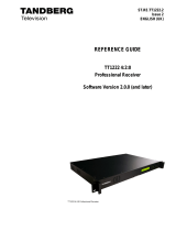
1.1.4 Information Labels
Typical Side Panel Information Label
Figure 1.2: Typical Side Panel Information Label
Label Definitions
Table 1.2 explains the terms carried on the Information label.
Table 1.2: Information Label Description
Label Legend Explanation
Product Type Describes the unit in plain English.
Serial Number A unique number given to the unit.
Unit Configuration Number The unit configuration number is in two parts separated by a dash.
The first part is the E number of the base unit before options are added, but includes the
basic boards for functionality.
The second part is an internally generated string number that varies with configurations.
For example: E10152-54
E10152: The base unit excluding any option cards.
54: An internally generated number.
Marketing Code A code that identifies the product for marketing purposes.
Bar Code A code used for unit identification in the manufacturing process.
SATELLITE MODULATOR
Serial No. 0001
E10152-xx
SM6610/BAS
Unit Configuration
Numbe
r
Serial Number of Unit
Bar Code
Marketing Code
Product Type

Introduction
Reference Guide: SM6610, SM6615, SM6620 and SM6625 Satellite Modulators Page 1-5
ST.RE.E10152.2
1.2 Role of the Modulator
The Modulator is designed specifically for the broadcasting of digital
satellite television signals to ETSI standards EN 300 421 (DVB-S) and
EN 301 210 (DVB-DSNG).
The unit is designed for the transmission of MPEG-2 digitally-compressed
video, audio and data services provided by the evolution 5000 range of
products, although it could be used with other types of equipment
providing the specification is compatible (see Annex B, Technical
Specification). The input data interfaces to the unit conform to the DVB
Asynchronous Serial Interface (DVB ASI) standard, and optionally the DVB
Synchronous Parallel Interface (DVB SPI) standard if the
SM66XX/HWO/ASI-SPI option is fitted.
The Modulator can be configured by its front panel, a VT100 terminal, or a
PC running a terminal emulator (see Figure 1.3). Alternatively, the
Modulator may be controlled remotely, either via its Ethernet ports or
RS-232/485 port.
Figure 1.3: Separated Modulator and Multiplexer Configuration
evolution 5000
Multiplexer
TANDBERG
1 2 3
4 5 6
7 8 9
0 * ±
Video
A
udio
Data
TANDBERG
1 2 3
4 5 6
7 8 9
0 * ±
evolution 5000
MPEG-2
Compression
Encoder
Video
A
udio
Data
TANDBERG
1 2 3
4 5 6
7 8 9
0 * ±
evolution 5000
MPEG-2
Compression
Encoder
Configuration
via
Ethernet
TANDBERG
▲
◄ ►
▼
TANDBERG
SM66XX Satellite
Modulator
Configuration
via PC or
VT100
High-power
Amplifier

Introduction
Page 1-6 Reference Guide: SM6610, SM6615, SM6620 and SM6625 Satellite Modulators
ST.RE.E10152.2
1.3 Summary of Features
1.3.1 MPEG-2 and DVB Compliance
The Modulator normally accepts an MPEG-2 transport stream in either
188-byte or 204-byte packet format. Alternatively, an internally generated
Pseudo Random Binary Sequence (PRBS) or Null Packets source may be
selected for test purposes. This does not require the presence of a
transport stream input.
1.3.2 Data Inputs
The Modulator base unit has two DVB ASI electrical inputs. When fitted
with the SM66XX/HWO/ASI-SPI option, the Modulator has two additional
DVB ASI electrical inputs (making four in total) and one DVB SPI input.
The incoming data may be in any of the following three formats:
• 188-byte packets (188 data bytes, contiguous packets)
• 204-byte packets (188 data bytes and 16 RS coding bytes; the coding
bytes are ignored)
• 204-byte packets (188 data bytes and 16 dummy bytes)
1.3.3 Transport Stream Rate Adaptation
The modulator is capable of performing transport stream rate adaptation
with PCR correction, allowing it to be used at a fixed symbol rate
irrespective of the transport stream input data rate. Rate adaptation may
be switched on or off under user control. See Section 7.3.2, Transport
Stream Rate Adaptation for further details of the rate adaptation function.
1.3.4 IF Output Models
Modulator models SM6610 and SM6620 have a tuneable 50-180 MHz IF
output. Both main and monitor outputs are provided on these models.
1.3.5 L-Band Output Models
Modulator models SM6615 and SM6625 have a tuneable 950-1750 MHz
L-band output. Both main and monitor outputs, and an L-band carrier
combining input are provided on these models. 24 V dc power and a
10 MHz reference frequency output, both switchable, are provided via the
main L-band output connector for use by an external frequency up-
converter.
1.3.6 PREKOR™ Models
Modulator models SM6620 and SM6625 incorporate Tandberg Television’s
proprietary PREKOR™ Dynamic Pre-correction system. This system
corrects non-linear magnitude and phase distortions, and group delay
distortion introduced by the uplink HPA and satellite transponder. It is of
particular benefit when using higher order modulations such as 16QAM.
NOTE…
The SM66XX/SWO/PREKOR software option must be installed to enable the PREKOR™ system.

Introduction
Reference Guide: SM6610, SM6615, SM6620 and SM6625 Satellite Modulators Page 1-7
ST.RE.E10152.2
1.3.7 Forward Error Correction Coding
Noise and interference can cause some bits to be received in error.
Therefore, Forward Error Correction (FEC) consisting of Reed-Solomon
(RS) coding followed by convolutional coding is used to add extra bits to
the transmitted signal. This allows a large number of errors at the receiver
to be corrected by Viterbi decoding followed by RS decoding.
Five convolutional code rates are available with BPSK and QPSK
modulations:
1
⁄
2
,
2
⁄
3
,
3
⁄
4
,
5
⁄
6
and
7
⁄
8.
These provide different compromises
between bit-rate and ruggedness. For 8PSK and 16QAM modulations,
pragmatic trellis coded modulation (PTCM) is used. PTCM code rates of
2
⁄
3
,
5
⁄
6
and
8
⁄
9
are available with 8PSK modulation. PTCM code rates of
3
⁄
4
and
7
⁄
8
are available with 16QAM modulation.
Data are interleaved between the outer RS Encoder and the inner
convolutional or PTCM Encoder in order to aid error correction techniques
at the receiver.
1.3.8 Modulation Schemes
BPSK and QPSK modulations are available as standard on each base unit
model. Additionally, 8PSK and 16QAM modulations are available with the
SM66XX/SWO/HOM option.
1.3.9 Symbol Rate Range
Each base unit model has a symbol rate range of 1 to 48 Msymbol/s as
standard. An extended symbol rate range of 0.2 to 66 Msymbol/s is
available with the SM66XX/SWO/HS option.

Introduction
Page 1-8 Reference Guide: SM6610, SM6615, SM6620 and SM6625 Satellite Modulators
ST.RE.E10152.2
1.4 Key Features
1.4.1 Standard Features
•
QPSK modulation in accordance with ETSI standard EN 300 421
(DVB-S)
• Variable symbol rate operation: 1 to 48 Msymbol/s
• User selectable spectrum roll-off factor: 20%, 25%, 30% and 35%
• Two DVB ASI electrical inputs
• Transport stream rate adaptation with PCR correction
• IF output frequency: 50 to 180 MHz, tuneable in 1 kHz steps (Models
SM6610 and SM6620)
• L-band output frequency: 950 to 1750 MHz, tuneable in 1 kHz steps
(Models SM6615 and SM6625)
• Low spurious IF/L-band outputs
• Front panel LCD display and 6-button keypad
• RS-232/485 control, backwards compatible with System 3000 and
evolution 5000 SM5600 Satellite Modulators
• Dual-redundant 10BaseT Ethernet control
• Software and firmware easily upgraded by remote Ethernet FTP
• Feature enabling by factory entry of licence keys
1.4.2 Optional Features
•
Two additional DVB ASI electrical inputs (i.e. four in total) and one
DVB SPI input
• Higher order modulation in accordance with ETSI standard EN 301 210
(DVB-DSNG): 8PSK and 16QAM
• PREKOR™ Dynamic Pre-correction (available on models SM6620 and
SM6625 only)
• Extended symbol rate range: 0.2 to 66 Msymbol/s
1.5 Applications
1.5.1 DVB Applications
•
Satellite DTH broadcasting
• Satellite distribution
• DSNG systems where a separate Modulator is required
• SCPC and MCPC systems
1.5.2 Non-DVB Applications
•
Telecommunications
• Internet backbone

Introduction
Reference Guide: SM6610, SM6615, SM6620 and SM6625 Satellite Modulators Page 1-9
ST.RE.E10152.2
1.6 Additional Features for Greater Flexibility
1.6.1 Spectrum Sense
The Modulator output spectrum can be reversed if required. This gives
greater flexibility when converting the signal to RF (Ku-band or C-band),
since the choice of local oscillator frequency for the conversion can itself
either lead to a normal or reversed spectrum.
1.6.2 Control and Monitoring
Local Control
Control and monitoring may be performed locally via a VT100 terminal or
a PC running appropriate software using the RS-232/485 port.
Remote Control
In addition to the RS-232/485 port, remote control is possible using either
one of the Ethernet ports. The user may also control the Modulator via
Telnet (see Chapter 3, Operating the Equipment Locally).
User Selectable Functions
The control and monitoring functions that may be performed by both types
of terminal are similar. The user may set, amongst others:
• Transport stream input source, PRBS or Null Packets selection
• Bit-rate or symbol rate
• Rate adaptation on/off
• Modulation format: BPSK, QPSK, 8PSK (option), 16QAM (option)
• FEC code rate
• IF frequency or uplink frequency
• IF power
• IF Output on/off
• Modulation on/off
• Spectrum sense
• Health/status monitoring
• Self-tests

Introduction
Page 1-10 Reference Guide: SM6610, SM6615, SM6620 and SM6625 Satellite Modulators
ST.RE.E10152.2
1.7 Guided Tour
1.7.1 Construction
The Modulator is constructed using a shielded self-ventilated enclosure. All
inputs and outputs are via rear-panel connectors. The unit may be
operated freestanding or mounted in a 19-inch rack; 1U rack height is
required.
1.7.2 Controls and Indicators
Operating Controls
The Modulator may be controlled by the LCD display and pushbutton
keypad. The front panel offers a choice of two interface levels, either
monitoring only or full access control (refer to Chapter 4, Front Panel
Control).
Front Panel Indicators
The Modulator provides two LED indicators. These are located at the
left-hand side of the unit (see Figure 1.4).
Figure 1.4: Front Panel LEDs
Table 1.3: Modulator LED Indicators
Indicator Description
Alarm The red LED indicates when an alarm condition is present.
Power The green LED is illuminated when ac power is applied.
Green Power LED
Red Alarm LED

Introduction
Reference Guide: SM6610, SM6615, SM6620 and SM6625 Satellite Modulators Page 1-11
ST.RE.E10152.2
1.7.3 Rear Panel Connectors
All input and output connectors are located at the rear panel (see
Figure 1.5 to Figure 1.8).
For pin-out information, see Chapter 2, Installation. For specifications of
the connector interfaces, see Annex B, Technical Specification.
Figure 1.5: View of the SM6610 Modulator Rear Panel
Figure 1.6: View of the SM6615 Modulator Rear Panel
Figure 1.7: View of the SM6620 Modulator Rear Panel
Figure 1.8: View of the SM6625 Modulator Rear Panel
1.8 Input Option Module
The SM6600 Satellite Modulator chassis design allows the fitting of an
input option module, providing the capability for the Modulator to accept
input data streams in alternative formats. The following options are
currently available:
• DVB ASI & SPI Input Card (S13450)
1.9 Getting Started
The following check list provides a guide as to what needs to be done to
get the equipment up and running.

Introduction
Page 1-12 Reference Guide: SM6610, SM6615, SM6620 and SM6625 Satellite Modulators
ST.RE.E10152.2
1. Switch on the Modulator. With the Modulator correctly installed and
connected to the input and output equipment, switch on the unit in
accordance with the instructions given in Chapter 2, Installing the
Equipment. Confirm that it powers up correctly. If it does not, refer to
Chapter 8, Preventive Maintenance and Fault-finding.
2. Establish local or remote control. Connect the relevant terminal to the
RS-232/485 port or the Ethernet Port (1 or 2). Ensure the terminal is
switched on and operational (see Chapter 3, Operating the Equipment
Locally for instructions on how to establish control from the local
terminal or from the remote terminal).
NOTE…
The rear panel connector is compatible with either RS-232 or RS-485, depending upon the mode
selected on the Modulator. (See Section 3.7 System Menu, Option 4, Serial Port Configuration.)
3. Select configuration parameters. Set the required configuration
parameters (see Chapter 3, Operating the Equipment Locally for
instructions on how to select parameters from the local terminal).
4. Implement the configuration. Ensure the required configuration
parameters are sent from the terminal to the Modulator and that they
are implemented.
/