Page is loading ...

Owners Manual
Models:
200-USRO, 200-USRO-P
REVISION # 1.3
REVISION DATE March 11, 2015
US Water Systems Corporate Office
1209 Country Club Road
Indianapolis, IN 46234
American Revolution 5-Stage RO System
The only RO System on the market that is totally American-Made!
Visit us online at
www.uswatersystems.com

MEMBRANE
POST
CARBON
PRE
SEDIMENT
PRE
CARBON
Parts Check List
RO Module
Tubing Bundle
Filter Wrench
Drain Saddle
Tank Valve
Angle Stop Feed Valve
Tank and Side Mount Tank
Stand
Faucet and Mounting Kit
Faucet Connector
Pre and Post Filters
Membrane
Installation Instructions
FILTER
WRENCH
DRAIN
SADDLE
FEED WATER
ANGLE STOP
TANK
VALVE
FAUCET
CONNECTOR
TUBING
FAUCET
AND
MOUNTING
KIT

Installation Instructions
Residential Reverse Osmosis Drinking Water System
Page 3
PRE-FILTER (sediment filter) removes larger particles
such as sand, silt, rust and scale, (activated carbon filters)
remove chlorine in the feed water to protect the reverse
osmosis membrane.
REVERSE OSMOSIS MEMBRANE reduces
dissolved minerals, metals and salts. During the process,
harmful compounds are separated by the membrane and
the reject water goes to waste (drain).
An activated carbon POST-FILTER is provided for a final
“polish” and to remove foul tastes, odors and to provide
great tasting drinking water.
FILTER HOUSINGS and R/O MODULE hold pre-filters
and membranes. A BRACKET is provided so they may
be mounted, typically below sink.
STORAGE TANK holds filtered water, ready for use.
AUTOMATIC SHUT-OFF VALVE (ASO) senses
when the storage tank is full and closes the water supply
to conserve water. (not used in permeate pump system)
PERMEATE PUMP is used to pressurize the tank and
distribution system. This pump is operated by the drain
water. The permeate pump will dramatically increase the
faucet pressure. A permeate pump system will not have
an ASO valve.
The dedicated FAUCET is used to dispense RO
produced water when needed.
FEED WATER ANGLE STOP VALVE is connected to
the cold water line to supply water to the R/O system.
WASTE WATER SADDLE VALVE is connected to the
drain to remove reject water from the R/O system.
TUBING supplies feed and reject water.
FITTINGS are used for necessary hose connections.
Components of the RO System

Installation Instructions
Residential Reverse Osmosis Drinking Water System
Page 4
The following tools may be necessary, depending on each particular installation:
3/8” Drill and ¼” drill bit and Faucet Drill bit (Standard Faucet use a 7/16” drill bit, Air Gap Faucet uses a 7/8” mini-
mum and 1 1/8” maximum drill bit).
Phillips head and flat blade screwdrivers
Adjustable wrench
Crescent wrench
Teflon tape
Plastic tube cutter
Your R/O system may be installed under a sink, in a basement or other location, depending on available space. Do not
install unit where temperatures fall below freezing; otherwise, damage will result. Connection to an icemaker should also
be considered for optimum performance.
Guidelines for component placement are as follows:
FAUCET should be placed near the sink where drinking/ cooking water is normally required. A 2” flat surface is re-
quired to mount the faucet if an existing hole for a second faucet is not available. The thickness of the mounting thick-
ness should not exceed 1-1/4”.
STORAGE TANK may be placed where it is convenient, within ten feet of the RO module. Under the sink or in a
nearby cabinet are excellent choices. Full tanks may weigh more than thirty pounds, so a sturdy shelf is required.
RO MODULE may be mounted on either side of the sink, in a cabinet or heated basement, with nearby access to a po-
table, cold water line and a sanitary drain.
Tools
Location

Installation Instructions
Residential Reverse Osmosis Drinking Water System
Page 5
NOTE: All plumbing must be completed in accordance
with state and local plumbing codes. Some
municipalities may require the installation be
performed by a licensed plumber. Check your local
authority prior to installation.
A. Faucet installation
If the sink has a sprayer it may be disconnected for
faucet installation. A pipe cap or plug will be
necessary to seal the sprayer connection. To make
the faucet mounting hole (if sprayer or second hole is not
used), check below to make sure the drill does not
interfere with anything below. Drill a 7/8” minimum 1 1/8”
maximum hole for air gap faucet installations. Be sure to
use a bit compatible with your surface. Clean up sharp
edges. The faucet should be positioned so it
empties into the sink and the spout swivels freely for
convenience. If sink has a hole that can
accommodate the RO faucet, no drilling is required.
Proceed with mounting the faucet.
FEED WATER CONNECTION is accomplished with an angle stop feed water valve. This valve will be installed in
the cold water line between the sink cold water shutoff valve and the sink faucet tubing. Connect to a potable, cold wa-
ter supply line only.
NOTE: Softened water is preferred since it will extend the life of your R/O membrane.
DRAIN CONNECTION is accomplished using a waste water saddle valve which is designed to fit around a standard
1-1/2” OD drain pipe. The drain saddle valve should always be installed above (before) the trap and on the vertical or
horizontal tailpiece.
Do not install the drain saddle valve near a garbage disposal; otherwise, plugging of the waste water line may occur. If dis-
charging into a utility sink or standpipe, an air gap may be needed. (Air gaps must be 1” or greater above the floor or pipe
rim). US Water offers other drain line connection options on www.uswatersystems.com
RO System Installation Procedure
Fig. 1

Installation Instructions
Residential Reverse Osmosis Drinking Water System
Page 6
B. Mounting the faucet
1. Install the faucet as shown in Fig. 1 on the previous page.
Assistance may be needed to hold the faucet in place
while the nut is tightened. Install the finished washer on
the faucet.
2. Install the rubber washer on the faucet.
3. Install the plastic sleeve on the threaded rod.
4. Install the brass washer on the threaded rod.
5. Install the brass nut on the threaded rod.
6. Install the faucet in the sink and slide the plastic “U”
washer on the bottom of the sink on the faucet.
7. Tighten the nut on the faucet. Be sure the plastic sleeve is
in the correct position for the drain line barb connections.
The faucet should be held in the correct position when it is
tightened to the sink.

Installation Instructions
Residential Reverse Osmosis Drinking Water System
Page 7
8. Once the faucet is secure, install the 7/16” UNS x 3/8” QC
faucet connector on the threaded nipple. This fitting
doesn’t require sealant. This fitting will seal at the beveled
surface. Tighten the fitting hand tight then an additional ½
turn with a wrench or pliers.
9. Now push the blue tube into the faucet connector. Leave
the other end of the blue tube unconnected for now, it will
be connected later in the installation.
10. If the air gap portion of the faucet is being used continue to
the next steps. Push the 1/4” drain line from the RO
module on to the smaller brass barb on the bottom of the
faucet. Be sure the tube is completely pushed on the barb
or a leak could occur.
10. Now push the supplied piece of 3/8” black tubing on the
larger brass barb on the bottom of the faucet. Be sure the
tube is completely pushed on the barb or a leak could
occur.

Installation Instructions
Residential Reverse Osmosis Drinking Water System
Page 8
C. Feed Water Angle Stop Valve and Tubing
Installation
1. To install the angle stop valve, turn off the cold water
supply valve for the sink faucet. Open the sink faucet cold
water and relieve the pressure. Remove the sink faucet
“whip hose” or tubing from the shutoff valve. There will be
residual water spilled when this tube is removed. Be sure
to have a towel to dry the water that is spilled.
2. Now install the gasket/bushing in the angle stop valve tee.
3. Install the tee on the sink faucet shutoff valve and tighten
it .

Installation Instructions
Residential Reverse Osmosis Drinking Water System
Page 9
4. Now install the whip hose or tubing on the angle stop
valve and tighten.
5. Now push the angle stop valve in the tee.
6. Push the orange supply tubing in the angle stop valve and
install the lock clip. Leave the other end of this tubing
unconnected for now, it will be connected later in the
installation.
7. Be sure the dark gray handle on the angle stop valve is in
the closed position. Now open the sink shutoff valve and
check the angle stop connections for leaks. If there are
leaks repair them now.

Installation Instructions
Residential Reverse Osmosis Drinking Water System
Page 10
D. Drain Saddle Installation
Prior to drain saddle installation it is important to inspect the
condition of drain pipes to make sure they are not thin and frail.
Drain saddle valves are designed to be installed on standard 1
-1/2” OD drain pipe. Install the drain saddle valve above the
trap (between the sink and trap) and on the vertical or
horizontal tailpiece. Never install a drain saddle valve close to
the outlet of a garbage disposal or plugging of the RO drain
line may result.
Procedures
1. Remove the circle shaped knockout from the gasket.
2. Remove the backing paper and install the gasket on the
port side portion of the drain saddle. Be sure the gasket
hole is lined up with the port hole.
3. Position the port side of the drain saddle valve at selected
location and mark for the opening. Never position the
opening at the bottom. A side or top position is
recommended.
4. Drill a 3/8” hole at mark through one side of pipe. Be very
careful not drill through both sides of the pipe. Applying
small amounts of pressure and drilling slowly will help
prevent the drill from penetrating both sides of the pipe.

Installation Instructions
Residential Reverse Osmosis Drinking Water System
Page 11
5. Position both halves of the drain saddle on the drain pipe
so both holes are aligned. A screwdriver or drill bit may be
used to keep the hole in the pipe and the hole in the drain
saddle oriented during the tightening process.
6. Secure the drain saddle clamp on valve with bolts and
nuts provided. (Do not over tighten and make sure there is
equal space between saddle halves on each side when
fully tightened.)
7. If the air gap portion of the faucet is being used install the
3/8” black tubing from the faucet to the saddle valve and
install the clip. BE SURE THERE IS A STRAIGHT DROP
FROM THE FAUCET TO THE DRAIN SADDLE. A SAG
IN THIS TUBING WILL CAUSE A DRAIN WATER
BACKUP.
8. If the air gap portion of the faucet is not used, install the
stem reducing fitting to convert the saddle to 1/4” and
install the 1/4” black drain line from the RO module into the
stem reducer fitting in the drain saddle.

Installation Instructions
Residential Reverse Osmosis Drinking Water System
Page 12
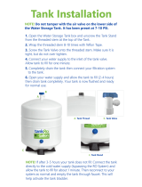
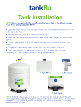
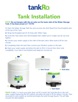
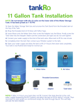
E. Tank Installation
1. Apply Teflon tape to the Tank outlet threads. About 3-4
wraps will be sufficient.
2. Install the tank valve by turning it clockwise. Tightening it
hand tight is usually adequate but additional tightening
may be required. Be sure not to overtighten the valve and
break the plastic.
3. Once the valve is installed, connect the green 3/8” tubing
to the tank valve install the locking clip. Leave the other
end of the tubing loose for now, it will be connected later in
the installation.
NOTE: Tanks are pre-pressurized at 7 psi. Prior to installation,
check, add or release as required.
F. Initial tubing connections
It may be desirable to leave the access tubing when making
the final connections. This will allow space to pull the unit out
of the cabinet for filter changes without disconnecting all the
tubing. If you want to secure the system and cut the tubing to
fit that is fine, but this may require that the system be removed
for filter changes or the filters will have to be changed with the
system in the cabinet which is sometimes difficult.
G. RO Filters and Membrane Installation
1. Install the sediment filter in the first sump. When
facing the unit, this would be the far right sump.
2. Remove the first sump from the system and install
the sediment filter in the sump.
3. Tighten the far right sump hand tight and secure it
with the supplied filter wrench by turning it an
additional 1/4 - 1/2 turn.

Installation Instructions
Residential Reverse Osmosis Drinking Water System
Page 13
4. Remove the center sump and install the carbon filter
in the sump. BE SURE that the rubber gasket is in
place on BOTH sides of the carbon filter.
5. Tighten the center sump hand tight and secure it
with the supplied filter wrench by turning it an
additional 1/4 - 1/2 turn.
6. Remove the far left sump and install the carbon filter
in the sump. BE SURE that the rubber gasket is in
place on BOTH sides of the carbon filter.
7. Tighten the far left sump hand tight and secure it with
the supplied filter wrench by turning it an additional
1/4 - 1/2 turn.

Installation Instructions
Residential Reverse Osmosis Drinking Water System
Page 14
Membrane Installation
1. Remove the 1/4” tubing from the membrane housing cap
by pressing the collet on the elbow fitting toward the fitting.
When the collet is flush with the fitting, the tubing will pull
out of the fitting with little effort. Refer to connections
instructions on Page 16.
2. Use the supplied wrench to remove the membrane
housing cap.
3. Remove the membrane from the protective
packaging and install it in the membrane housing.
There are two O-rings on end of the middle
membrane tube. Lightly lubricate these O-rings with
the supplied silicone grease.
4. BE SURE the membrane is fully seated in the
housing. If the membrane is fully seated, it will
about 1/8 - 1/4 inset from being flush with the
housing.

Installation Instructions
Residential Reverse Osmosis Drinking Water System
Page 15
5. Lubricate the O-ring on the membrane housing and install
the cap hand tight. Tighten the cap an additional 1/8 - 1/4
turn.
6. Push the 1/4” tubing back into the elbow fitting. BE SURE
it is fully seated in the fitting or a leak could occur.
H. RO unit installation
The RO unit is normally mounted to the sink cabinet sidewall,
depending on where supply tank is to be located. Generally
the unit is installed at the front of the cabinet and the tank at
the rear.
To mount the unit, elevate it at least 2” off the floor, level it and
mark the location of mounting holes needed. Drill holes for
mounting screws and install screws, allowing the mounting
bracket slots to slip over them.
NOTE: If the cabinet sidewalls are not solid, unit may sit
on the floor with screws to keep it against the cabinet in a
vertical position. The system doesn’t have to be secured
to the wall but it is a good practice. If the system is not
mounted to the cabinet wall and the tubing is not cut
short, the module and be removed from the cabinet
during filter changes.
I. Final tubing connections
With all components in place, complete final tubing
connections using these guidelines:
Tubing should follow contour of the cabinets.
Cut tubing to desired length using square cuts or a proper
cutting devise.
Make no sharp bends
Under sink installations following installation diagram and the
following procedures:
1. Connect the blue tubing from faucet to RO unit at the post
carbon filter outlet fitting.

Installation Instructions
Residential Reverse Osmosis Drinking Water System
Page 16
2. BE SURE the storage tank shutoff valve is in the closed
position. Use the supplied syringe and add 5ml of the
supplied sanitizing solution to the Green tank tubing
attached to the storage tank. Connect the open end of the
green tubing from tank to RO unit at the post carbon filter
inlet tee fitting. Leave the tank valve closed.
3. Connect orange tubing from the angle stop supply valve to
RO unit at the sediment filter inlet fitting.
Permeate Pump Installation
If the system is equipped with a permeate pump, clip the pump
to the membrane housing using the supplied mounting bracket
and make the connections to the pump using the label on the
pump and the labels on the tubing. There will be a Permeate
IN, Permeate OUT and Brine IN connection on the pump.
The Brine OUT connection will be made in the following step.
4. Connect the tubing from the drain saddle to the RO unit at
the flow restrictor on the membrane on a standard system
or on the “Brine Out” port on a permeate pump system. If
the air gap is being used, connect the black 1/4” line from
the faucet to the flow restrictor or to the “brine out” port on
the permeate pump.

Installation Instructions
Residential Reverse Osmosis Drinking Water System
Page 17
Icemaker hookup (optional)
The RO drinking water device can be connected to any
standard refrigerator ice maker or ice maker/water dispenser.
3/8” tubing must be used for ice maker connections. If your
system is using 1/4” tubing for the tank and faucet it will need
to be changed to 3/8” tubing. (Do not connect to a commercial
type bar ice maker.)
To complete this operation, connect a tee with shutoff valve
into the faucet tubing (Blue Line) and route tubing to the
refrigerator. (Hooking up to an existing copper line is not
recommended as RO water can cause the copper to leach into
the water stream). Shut off ice maker prior to turning off the
existing tap water supply line to the refrigerator. Connect the
RO system tubing to the ice maker inlet. Turn on ice maker
after the RO system has been flushed several times and the
tank has a full supply of water. There are detailed instructions
and a layout drawing on Page # 22 and 23 of the is manual.
NOTE: Before any service is performed on the RO system, turn
off ice maker valve and ice maker unit. Turn back on only after
RO tank has been flushed and is full of water.
System start-up
Prior to start-up
1. Check all connections to be sure they are secure.
2. Turn on feed water valve and check for leaks. (Turn off
and correct leaks if leaks occur.)
3. Close the valve (the tank should be closed from the
previous step) on storage tank and open faucet until a
steady stream of water flows. Water will be flowing to the
drain as well.
4. Once there is a steady stream of water coming from the
faucet (about 1/8” in diameter) close faucet and wait five
minutes to see if any leaks result on the entire system
(The initial water from the system may be discolored. This
is normal).
NOTE: BE PATIENT! It is very important that there is a steady
stream (not drips) of water coming from the faucet before it is
closed. If not, there could be air trapped in the system and it will
not fill the tank properly. This can waste a lot of water.
5. If there are no leaks, open the storage tank valve allow the
system to fill. Most systems will be full within 2 hours. The
system is full when the water to the drain stops. Check for
leaks with the system full and repair them accordingly.
NOTE: When the system is first turned on, water may
intermittently “spurt” from the air gap opening on the side of air
gap faucets. This is common and should correct itself after the
air is purged from the system.
Flushing system and checking operation
To make sure RO system is operating correctly, follow these
simple procedures:
1. Open faucet handle and allow tank to completely drain
(water will be discolored and will have suds from the
sanitizing solution).
2. Close faucet and re-fill the system.
3. Allow system to process water for approximately 2-3
hours, at which point tank will be practically full.
4. Open faucet again and allow tank to empty for a second
time. Do not use this water.
5. Wait another 2-3 hours to allow tank to re-fill.
Air Purging
If the tank doesn’t fill, the tank tubing may have air in it.
Typically the standard startup procedure will be sufficient but in
some cases due to the water temperature and pressure,
additional air bleeding must be performed. The following
procedure will help bleed air from the system.
1. Close the tank valve and the feed water valve and open
the faucet to relieve the pressure on the system.
2. Remove the tank tubing from the tank valve and hold it
over a bucket or pan.
3. Open the feed water valve and the faucet.
4. Allow the system to run until there is a stream of water
coming from the tank tubing.
5. Once there is a steady stream coming from the tank
tubing, push it back into the tank valve. BE SURE to push
it in the tank valve completely or a leak could occur.
6. Allow the system to continue to operate until there is a
steady stream coming from the faucet.
7. Once there is a steady stream coming from the faucet,
close the faucet and open the tank valve. Then go to the
flushing procedure above.
NOTE: If no objectionable tastes are noticed after second tank
draining, RO processed water is ready for use. Otherwise, drain
tank and re-fill for a third time.
At this point supply line to ice maker connection (optional) may
be opened.

Installation Instructions
Residential Reverse Osmosis Drinking Water System
Page 18
Maintenance
The RO system contains filters and membranes which must
be replaced periodically for proper operation.
NOTE: Filter change frequencies may be amended, depending
on source water conditions.
Sanitizing Filter Change Instructions
1. Turn off the feed water to the system and shut-off the
icemaker power and water supply valve (if applicable).
2. Turn on the faucet to relive any pressure on the system
and make sure water has stopped flowing out of the
faucet.
3. Remove the membrane and all the lower vertical sump
filters The post carbon filter can be left in place at this
time. Use rubber gloves and store the membrane in
water or a Ziploc bag to prevent damage or discard the
membrane if it is being replaced.
4. Use the included plastic syringe to collect 5ml of Sani-
System solution from the packet and set aside. Pour
the remainder of the packet of Sani-System directly
into the sediment filter housing (where inlet feed line
attaches). Reattach all filter housings and membrane
caps. Do not install the filters at this time. Remove the
tube that connects to the storage tank from the RO
module and invert it to remove the water from the tube.
If you have a fitting with a nut, disconnect it. If the fitting
is a quick-connect type (push-to-fit) then you just push
in the locking collet and pull the tube out. Inject all of
the Sani-System solution from the plastic syringe into
the line. Reattach tank tube. Make sure RO water
faucet is closed and turn on water supply.
5. Allow system to fill with water. The time will vary
depending on the water pressure. However, the system
should be full within 5 – 10 minutes without the filters or
membrane. Allow system to rest for 10 minutes. Open
faucet and allow to drain for 10 minutes then close
faucet. Allow the system to fill and rest for another 10
minutes, then open faucet again and allow system to
flush for another 10 minutes. Shut off inlet supply and
open faucet to depressurize the system. Remove the
sumps and install the filters and membrane.
6. The white fiber-type filter is installed in the INLET
(sediment) filter sump. Lubricate the o-ring at the top
of the sump with a small amount of the silicone
included. Tighten the filter sump hand tight, then using
the wrench, turn an additional ¼ turn, but do not over
tighten.
7. The carbon block filter(s) are installed into the next
sump (for 3 & 4-Stage) or the next two sumps (for 5-
Stage). Lubricate the O-ring at the top of the sump
with a small amount of the silicone included. Be sure
the rubber gaskets are in place on both sides of the
carbon block filter. Tighten the filter sump hand tight,
then using the wrench, turn an additional ¼ turn, but do
not over tighten.
8. The inline filter is installed on the top of the membrane
(does not apply on 3-Stage systems). The fittings in
each end of the old post filter must be removed and
wrapped with a couple of layers of ½” Teflon tape
around the fitting (when looking at the threaded side of
the fitting, always wrap the Teflon tape in a clockwise
manner). The tee fitting will screw into the inlet side of
the new filter and the elbow fitting to the outlet side.
Re-install the tubing and make sure everything is
sealed.
9. Turn on feed water valve and check for leaks. (Turn off
and correct leaks if leaks occur.)
10. Close the valve on storage tank and open faucet until a
steady stream of water flows. Water will be flowing to the
drain as well.
11. Once there is a steady stream of water coming from the
faucet (about 1/8” in diameter) close faucet and wait five
minutes to see if any leaks result on the entire system
(The initial water from the system may be discolored. This
is normal).
NOTE: BE PATIENT! It is very important that there is a steady
stream (not drips) of water coming from the faucet before it is
closed. If not, there could be air trapped in the system and it will
not fill the tank properly. This can waste a lot of water.
12. If there are no leaks, open the storage tank valve allow the
system to fill. Most systems will be full within 2 hours. The
system is full when the water to the drain stops. Check for
leaks with the system full and repair them accordingly.
NOTE: When the system is first turned on, water may
intermittently “spurt” from the air gap opening on the side of air
gap faucets. This is common and should correct itself after the
air is purged from the system.
Replacement part Frequency
Pre-filter (sediment) Every 6-12 months.
Pre-filters (activated carbon) Every 6-12 months.
R/O membrane Every 3-5 years
Post filter (carbon) Every 6-12 months.

Installation Instructions
Residential Reverse Osmosis Drinking Water System
Page 19
Flushing system and checking operation
To make sure RO system is operating correctly, follow these
simple procedures:
1. Open faucet handle and allow tank to completely drain
(water will be discolored and will have suds from the
sanitizing solution).
2. Close faucet and re-fill the system.
3. Allow system to process water for approximately 2-3
hours, at which point tank will be practically full.
4. Open faucet again and allow tank to empty for a second
time. Do not use this water.
5. Wait another 2-3 hours to allow tank to re-fill.
Air Purging
If the tank doesn’t fill, the tank tubing may have air in it.
Typically the standard startup procedure will be sufficient but in
some cases due to the water temperature and pressure,
additional air bleeding must be performed. The following
procedure will help bleed air from the system.
1. Close the tank valve and the feed water valve and open
the faucet to relieve the pressure on the system.
2. Remove the tank tubing from the tank valve and hold it
over a bucket or pan.
3. Open the feed water valve and the faucet.
4. Allow the system to run until there is a stream of water
coming from the tank tubing.
5. Once there is a steady stream coming from the tank
tubing, push it back into the tank valve. BE SURE to push
it in the tank valve completely or a leak could occur.
6. Allow the system to continue to operate until there is a
steady stream coming from the faucet.
7. Once there is a steady stream coming from the faucet,
close the faucet and open the tank valve. Then go to the
flushing procedure above.
NOTE: If no objectionable tastes are noticed after second tank
draining, RO processed water is ready for use. Otherwise, drain
tank and re-fill for a third time.
At this point supply line to ice maker connection (optional) may
be opened.
Why the regular use of Sani-System is important.
A reverse osmosis system should be sanitized regularly to
maintain quality service levels. If the system is not properly
maintained, bacteria can begin to grow and multiply
wherever the water sits, including on the inside surfaces of
tanks and hoses. Filling the system with impure water can
also be a cause, but over time, bacteria grows — even in
chlorinated water. When water sits in a tank or hose,
chlorine levels drop, reducing its chemical ability to prevent
bacterial growth. Filters can also filter out chlorine, making
the water more susceptible to bacterial growth. In addition,
system equipment such as hoses, filters and canisters can
harbor and help to support bacterial growth.
Sani-System is the only EPA & NSF approved sanitizer for
use in reverse osmosis units. It is proven to kill 99.9% of
harmful bacteria without the use of chlorine, oxidizers or
acids that can harm system parts. Sani-System maintains
the performance of your reverse osmosis system and
restores it to peak efficiency.

Installation Instructions
Residential Reverse Osmosis Drinking Water System
Page 20
Water quality
Water quality from an RO system is normally determined with
a TDS Meter, which measures total dissolved solids in water,
measuring conductivity. The results are normally measured in
parts per million or milligrams per liter. Fewer dissolved solids
results in higher quality water.
RO membranes are rated by the amount of dissolved solids
they reject expressed as “rejection percentage”.
For example:
If feed water contains 100 ppm of dissolved solids and the
product water after the membrane has 10 ppm of dissolved
solids the rejection rate is 90%.
The formula is as follows:
RO membranes should operate between an 80-97% rejection
rate. Once the rejection falls below 80%, the membrane must
be replaced.
Water production
PRODUCT WATER RATE
Usable water production from an RO system is designated
product water rate, produced on a daily basis. The rate is
normally described in gallons per day (gpd) or milliliters
per minute (ml/min).
REJECT WATER RATE
The flow of water to drain is designated as reject water
rate, as measured in gallons per day (gpd) or milliliters per
minute (ml/min).
Using a graduated cylinder the formulas are:
REJECT RATIO
The reject ratio is the amount of water produced
compared to the amount of water flowing to drain.
The formula is as follows:
PERCENT RECOVERY
The percent recovery is another way to measure the amount
of water produced compared to the amount of water which is
actually used.
The formula to determine percent recovery is as
follows:
NOTE: Product water rate is the sum of the feed water
flow rate and reject water flow rate.
For example:
Water pressure and temperature
Product water quality and production of RO systems is
dependent on pressure and temperature. Typically, RO
membranes are treated at standard conditions of 77°F (25°C)
and 60 psi (4 bar) discharging to atmosphere. In general, the
higher the pressure differential and temperature, the greater
the quality and quantity of water produced. These factors
should be considered when sizing RO systems for a particular
application.
Milliliters per minute x 0.38
= gallons per day
Ounces per minute x 11.2
= gallons per day
Product water rate =10 gpd
Reject water rate = 40 gpd
Feed water = (10 gpd + 40 gpd) or 50 gpd
Percent Recovery
= 20%
Percent Rejection
=
(Feed H2O TDS - Product H2O TDS) x 100%
Feed H
2
O
Reject Ratio =
Reject Rate
Product Rate
Percent Recovery
=
Product H
2
O Rate x 100%
Feed H
2
O Rate
/