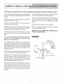
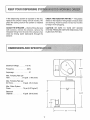
Sears 625.34929 Solution Dispensing System is designed to treat water problems commonly found in well water systems. It can remove iron, hydrogen sulfide, and acid from water, and it can also kill iron bacteria. The system is easy to install and use, and it comes with a one-year warranty.
Sears 625.34929 Solution Dispensing System is designed to treat water problems commonly found in well water systems. It can remove iron, hydrogen sulfide, and acid from water, and it can also kill iron bacteria. The system is easy to install and use, and it comes with a one-year warranty.


-
 1
1
-
 2
2
-
 3
3
-
 4
4
-
 5
5
-
 6
6
-
 7
7
-
 8
8
-
 9
9
-
 10
10
-
 11
11
-
 12
12
-
 13
13
-
 14
14
-
 15
15
-
 16
16
-
 17
17
-
 18
18
-
 19
19
-
 20
20


Sears 625.34929 Solution Dispensing System is designed to treat water problems commonly found in well water systems. It can remove iron, hydrogen sulfide, and acid from water, and it can also kill iron bacteria. The system is easy to install and use, and it comes with a one-year warranty.
Ask a question and I''ll find the answer in the document
Finding information in a document is now easier with AI
Other documents
-
 UPCART MPB-1DX Installation guide
-
Pulsafeeder X030-XC-BAA8XXX Owner's manual
-
Pulsafeeder X068-XA-AAASXXX Owner's manual
-
Superior Pump 96210-96215-96220 Owner's manual
-
-
Kenmore 625348233 Owner's manual
-
-
-
-
