
Model SU444
OPERATORS MANUAL
Manual No. 513639 Rev.3


This manual provides basic information about the machine. Instructions and suggestions are
given covering its operation and care.
The illustrations and specifi cations are not binding in detail. We reserve the right to make
changes to the machine without notice, and without incurring any obligation to modify or pro-
vide new parts for machines built prior to date of change.
DO NOT ATTEMPT to operate the machine until instructions and safety precautions in this
manual are read completely and are thoroughly understood. If problems develop or questions
arise in connection with installation, operation, or servicing of the machine, contact Stoelting.
Stoelting Foodservice Equipment
502 Highway 67
Kiel, WI 53042-1600
U.S.A.
Main Tel: 800.558.5807
Fax: 920.894.7029
Customer Service: 888.429.5920
Fax: 800.545.0662
Email: [email protected]
© 2014 PW Stoelting, LLC
stoeltingfoodservice.com

Safety Alert Symbol:
This symbol Indicates danger, warning or caution.
Attention is required in order to avoid serious per-
sonal injury. The message that follows the symbol
contains important information about safety.
Signal Word:
Signal words are distinctive words used throughout
this manual that alert the reader to the existence and
relative degree of a hazard.
CAUTION
The signal word “CAUTION” indicates a potentially
hazardous situation, which, if not avoided, may result
in minor or moderate injury and equipment/property
damage.
A Few Words About Safety
Safety Information
Read and understand the entire manual before
operating or maintaining Stoelting equipment.
This manual provides the operator with information
for the safe operation and maintenance of Stoelting
equipment. As with any machine, there are hazards
associated with their operation. For this reason safety
is emphasized throughout the manual. To highlight
specifi c safety information, the following safety defi ni-
tions are provided to assist the reader.
The purpose of safety symbols is to attract your at-
tention to possible dangers. The safety symbols, and
their explanations, deserve your careful attention
and understanding. The safety warnings do not by
themselves eliminate any danger. The instructions
or warnings they give are not substitutes for proper
accident prevention measures.
If you need to replace a part, use genuine Stoelting
parts with the correct part number or an equivalent
part. We strongly recommend that you do not use
replacement parts of inferior quality.
WARNING
The signal word “WARNING” indicates a potentially
hazardous situation, which, if not avoided, may result
in death or serious injury and equipment/property
damage.
CAUTION
The signal word “CAUTION” not preceded by the
safety alert symbol indicates a potentially hazardous
situation, which, if not avoided, may result in equip-
ment/property damage.
NOTE (or NOTICE)
The signal word “NOTICE” indicates information or
procedures that relate directly or indirectly to the
safety of personnel or equipment/property.

Section Description Page
1 Description and Specifi cations
1.1 Description ..................................................................................................1
1.2 Specifi cations .............................................................................................2
2 Installation Instructions
2.1 Safety Precautions .....................................................................................3
2.2 Shipment and Transit ..................................................................................3
2.3 Machine Installation ....................................................................................3
2.4 Installing Permanent Wiring ........................................................................3
2.5 Check Check Compressor for Proper Power .............................................4
2.6 Check Blender Rotation ..............................................................................4
2.7 Mix Pump ....................................................................................................4
A. Mix Pump Hose Installation..................................................................................4
B. Mix Pickup Hose Installation ................................................................................5
C. Mix Low Level Indicator Adjustment .....................................................................6
3 Initial Set-Up and Operation
3.1 Operator’s Safety Precautions ....................................................................7
3.2 Operating Controls and Indicators ..............................................................7
3.3 Important Information Regarding Cleaning and Sanitizing .........................9
3.4 Disassembly of Left Side ............................................................................10
A. Remove Front Door and Auger ............................................................................11
3.5 Disassembly of Right Side ..........................................................................11
A. Remove Blender (SU444 Only)............................................................................11
B. Remove Front Door and Auger ............................................................................11
3.6 Cleaning Disassembled Parts ....................................................................12
3.7 Sanitizing Parts ...........................................................................................12
3.8 Cleaning the Machine .................................................................................12
3.9 Assembling the Left Side ............................................................................12
3.10 Assembling the Right Side .........................................................................13
3.11 Sanitizing ....................................................................................................14
3.12 Initial Freeze Down and Operation .............................................................15
A. Adding Mix ...........................................................................................................15
B. Preparing the IntelliTec Control ............................................................................15
C. Initial Freeze Down ..............................................................................................15
D. Adjusting the IntelliTec Control .............................................................................15
E. Serving Product....................................................................................................16
3.13 Normal Freeze Down and Operation ..........................................................16
3.14 Mix Information ...........................................................................................17
3.15 Operation of Mix Pump ...............................................................................17
3.16 Mix Pump Cleaning ....................................................................................17
3.17 Disassembly and Inspection of Removable Parts ......................................18
TABLE OF
CONTENTS

Section Description Page
4 Maintenance and Adjustments
4.1 Machine Adjustment ...................................................................................19
4.2 Product Temperature Adjustment (Left Side) ..............................................19
4.3 Product Consistency Adjustment (Right Side) ............................................19
4.4 Locking the Control Panel (Right Side) ......................................................19
4.5 Obtaining Readings and Modifying Settings
(Service Personnel Only) (Right Side) ........................................................19
4.6 Readings (Service Personnel Only) (Right Side) .......................................20
4.7 Adjustments (Service Personnel Only) (Right Side) ...................................21
4.8 Other Settings (Service Personnel Only) (Right Side) ................................21
4.9 Overrun Adjustment ....................................................................................22
4.10 Mix Pump Hose Reposition ........................................................................23
4.11 Mix Pump Hose Replacement ....................................................................24
4.12 Cab Temperature Adjustment .....................................................................24
4.13 Drive Belt Tension Adjustment ....................................................................25
4.14 Condenser Cleaning (Air-Cooled Machines) ..............................................25
4.15 Preventative Maintenance ..........................................................................25
4.16 Extended Storage .......................................................................................26
5 Troubleshooting
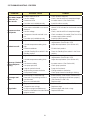
5.1 Error Codes (Right Side) ............................................................................27
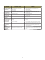
5.2 Troubleshooting - Error Codes (Right Side) ...............................................27
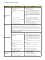
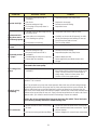
5.3 Troubleshooting - Machine .........................................................................29
5.4 Troubleshooting - Mix Pump .......................................................................31
6 Replacement Parts
6.1 Brushes, Decals and Lubrication ................................................................33
6.2 Left Side Auger Shaft and Front Door Parts ...............................................34
6.3 Right Side Auger Shaft and Front Door Parts .............................................35
6.4 Blender Parts and Drip Tray .......................................................................36
6.5 Cab Tubing .................................................................................................37

1
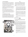
1.1 DESCRIPTION
The Stoelting SU444 and U444A fl oor model machines
are pressure fed. They are equipped with fully automatic
controls to provide a uniform product. The SU444 and
U444A are designed to dispense soft serve product from
the left side and shake product from the right side. The
SU444 has a blender attached to the front door of the
shake side.
This manual is designed to assist qualifi ed service per-
sonnel and operators with installation, operation and
maintenance of the SU444 and U444A.
SECTION 1
DESCRIPTION AND SPECIFICATIONS
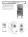
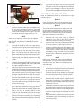
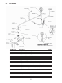
Figure 1-2 Dimensions
Figure 1-1 Model SU444 Machine

2
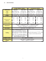
1.2 SPECIFICATIONS
SU444 Water Cooled SU444 Air Cooled
Dimensions Machine with crate Machine with crate
width 26-7/8’’ (68,3 cm) 34’’ (86,4 cm) 26-7/8’’ (68,3 cm) 34’’ (86,4 cm)
height 67-3/8’’ (171,1 cm) 78’’ (198,1 cm) 67-3/8’’ (171,1 cm) 78’’ (198,1 cm)
depth 40’’ (101,6 cm) 48’’ (121,9 cm) 40’’ (101,6 cm) 48’’ (121,9 cm)
Weight 760 lbs (344,7 kg) 908 lbs (411,8 kg) 760 lbs (344,7 kg) 908 lbs (411,8 kg)
Electrical 1 PH 3 PH 1 PH 3 PH
left right left right left right left right
minimum circuit
ampacity
31A 26A 19A 18A 32A 26A 20A 18A
maximum overcurrent
protection device
50A 40A 30A 25A 50A 40A 30A 25A
Compressor
Soft Serve - 19,000 Btu/hr Scroll™ Compressor (R-404A)
Shake - 15,000 Btu/hr Scroll™ Compressor (R-404A)
Cabinet - 1,300 Btu/hr Compressor (R-134a)
Drive Motor Soft Serve - 2 hp, Shake - 3/4 hp
Cooling
Water cooled units require 1/2” N.P.T.
water and drain fi ttings. Maximum
water pressure of 130 psi. Minimum
water fl ow rate of 3 GPM. Ideal EWT
of 50°-70°F. The machine requires 6”
(15,2 cm) air space on all sides for the
cabinet refrigeration system.
Air cooled units require 6” (15,2 cm) air
space on both sides and back.
Hopper Volume Two - 8 gallon (30,28 liters)
Freezing Cylinder
Volume
Soft Serve - 1.33 gallon (5,4 liters)
Shake - 2.1 gallon (7,95 liters)

3
SECTION 2
INSTALLATION INSTRUCTIONS
2.1 SAFETY PRECAUTIONS
Do not attempt to operate the machine until the safety
precautions and operating instructions in this manual are
read completely and are thoroughly understood.
Take notice of all warning labels on the machine. The la-
bels have been put there to help maintain a safe working
environment. The labels have been designed to withstand
washing and cleaning. All labels must remain legible for
the life of the machine. Labels should be checked periodi-
cally to be sure they can be recognized as warning labels.
If danger, warning or caution labels are needed, indicate
the part number, type of label, location of label, and quantity
required along with your address and mail to:
STOELTING
ATTENTION: Customer Service
502 Hwy. 67
Kiel, Wisconsin 53042
2.2 SHIPMENT AND TRANSIT
The machine has been assembled, operated and inspected
at the factory. Upon arrival at the fi nal destination, the
entire machine must be checked for any damage which
may have occurred during transit.
With the method of packaging used, the machine should
arrive in excellent condition. THE CARRIER IS RESPON-
SIBLE FOR ALL DAMAGE IN TRANSIT, WHETHER
VISIBLE OR CONCEALED. Do not pay the freight bill
until the machine has been checked for damage. Have
the carrier note any visible damage on the freight bill. If
concealed damage and/or shortage is found later, advise
the carrier within 10 days and request inspection. The
customer must place a claim for damages and/or short-
ages in shipment with the carrier. Stoelting, Inc. cannot
make any claims against the carrier.
2.3 MACHINE INSTALLATION
WARNING
Installation must be completed by a qualifi ed
electrician/refrigeration specialist.
Incorrect installation may cause personal injury,
severe damage to the machine and will void fac-
tory warranty.
Installation of the machine involves moving the machine
close to its permanent location, removing all crating, set-
ting in place, assembling parts, and cleaning.
A. Uncrate the machine.
B. Install the four casters. Turn the threaded end
into the machine until no threads are showing. To
level, turn out casters no more than 1/4” maximum,
then tighten all jam nuts.
C. The machine must be placed in a solid level
position.
NOTE
Accurate leveling is necessary for correct drainage
of freezing cylinder and to insure correct overrun.
D. Machines with air cooled condensers require a
minimum of 6” (15,2cm) space on all sides and
back for proper circulation.
NOTE
In order for the condenser fan motor to work the
left side needs to be connected to a power source.
E. Machines that have a water cooled condenser
require 1/2” NPT supply and drain fi ttings.
2.4 INSTALLING WIRING
A. Refer to the nameplate on the side panel of the
machine for specifi c electrical requirements. Make
sure the power source in the building matches
the nameplate requirements. Bring the wires into
the junction boxes through the access holes in
the bottom rear of the freezer.
NOTE
Three phase freezers in areas of unbalanced elec-
trical loads require special attention when connect-
ing input electrical power. The unbalanced leg of
power (called wild or high) must be connected to
L2 in the junction box.
B. Remove the back panel and the junction box
cover located at the bottom of the machine.
C. Install permanent wiring according to local code.
D. If the line voltage is less than 215V, the fan motor
needs to be rewired. Refer to the wiring diagram
for details.
NOTE
Low incoming voltage affects the fan motor speed
and could cause high head pressure errors from the
reduced air fl ow. Rewiring the fan motor prevents
the fan speed from decreasing to an unsuitable rate.

4
2.5 CHECK COMPRESSOR FOR PROPER
POWER (3 PHASE ONLY)
After connecting the electrical, check that the compressor
is operating in the proper direction.
A. Start a freezing cycle.
On the right side, place the Main Freezer Power
switch and Freezing Cylinder OFF/ON switch to
the ON position. Press the PUSH TO FREEZE
button.
On the left side, place the Clean/Off/Serve and
the Standby/Serve switches in the Serve position.
B. The suction line will be cold to the touch within 1
minute.
C. If it is not, disconnect power to the machine and
reverse L1 and L3 lines in the junction box.
D. After reversing the electrical lines, recheck the
suction line.
2.6 CHECK BLENDER ROTATION
After connecting the electrical, check the blender on the
right side for proper rotation.
A. Place the Blender Power Off/On switch to the ON
position.
B. With the clear swing sheild in place, move the
spigot handle to the right.
WARNING
Hazardous Moving Parts
Blender shaft and agitator can grab and cause
injury. Do not operate blender without protective
shield or swing splash shield.
C. The blender should rotate clockwise looking from
the top of the blender.
D. If the rotation is counterclockwise, refer to the
wiring diagram located behind the header panel
and check the diode direction. Reverse the diode
polarity if needed.
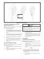
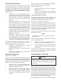
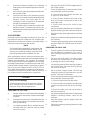
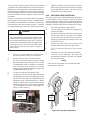
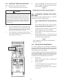
2.7 MIX PUMP
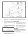
A. MIX PUMP HOSE INSTALLATION
Follow the steps below to install the mix pump hose in
the cabinet part of the machine.
1. Turn the mix pump on. The switch is located on
the header panel.
2. Feed one end of the mix pump hose into the
entering or pickup hose side (left) of black cover
(Fig 2-2).
NOTE
Feed the tube into the clamp so the natural curve of
the tube is towards the outside of the black cover.
This prevents the hose from looping around the
black cover twice.
3. Gently push the hose into the black cover until it
begins to feed.
Figure 2-2 Mix Hose Installation
6” (15cm)

5
4. Allow the hose to feed itself through the pump
until about 6” (15cm) remains on the entering
side.
5. Turn the pump off.
6. Connect the mix pump hose to the elbow fi tting
(located on the left side of the mix line manifold)
using a small hose clamp. Be careful not to twist
the mix hose.
7. Turn the pump on.
8. Allow the remaining 6” (15cm) of tubing to feed
through pump until the hose adapter prevents
further feeding.
9. Turn the pump off.
CAUTION
Risk of Product Damage
Air/Mix Tee must remain below the black cover
clamp. If the Tee is above the pump, mix may drain
into the air compressor resulting in pump damage.
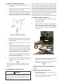
10. Connect the free end of the mix pump hose to
the 3-way Tee (Fig. 2-3). When all connections
are complete, the 3-way Tee must be lower than
the black pump housing.
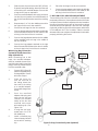
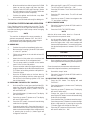
B. MIX PICKUP HOSE INSTALLATION
The machine may be connected to the standard mix
container or up to three prepacked mix bags. Follow the
instructions below that match your confi guration.
Standard Connection:
1. Place the mix pickup assembly through the hole
in the cover and install the retaining clip.
2. Connect a 24” (61cm) length of 3/8” (9,5mm)
ID plastic food grade tubing to the mix pickup
assembly. Secure with a hose clamp.
3. Connect the elbow fi tting to the free end of the
tubing. Connect the opposite end of the elbow
to 1/4” ID tan tubing on the left side of the pump
head. Secure with hose clamps (Fig. 2-3).
When Using Bag Connection System (BCS) with Three
Bags (optional kit):
The position of the three bags in the mix container is
important. The bag that is connected nearest the outlet
of the manifold will drain last and should be placed at
the back of the mix container. The mix low level indicator
relies on proper bag placement.
1. Connect 3/8” (9,5mm) ID plastic food grade tubing
to a bag adapter. Secure with hose clamps.
Figure 2-3 Mix Pump Connections for Standard Mix Container

6
2. Slide the hose clip over free end of 3/8” (9,5mm)
ID plastic food grade tubing. Attach the free end
of the tubing to a manifold adapter. Secure with
a large hose clamp or equivalent.
3. Push the manifold adapter with spring and valve
into the left port (nearest the manifold outlet) of
the mix inlet manifold and secure with a retaining
clip.
4. Repeat steps 1 to 3 for the middle port and for
the right port of the mix inlet manifold.
5. Place three mix bags into the mix container.
6. Connect the bag adapter attached to the left side
of the manifold (closest to the mix outlet) to the
mix bag in the back of the mix container.
7. Connect the bag adapter attached to the middle
of the manifold to the mix bag in the middle of
the mix container.
8. Connect the bag adapter attached to the right
side of the manifold (farthest from the mix outlet)
to the mix bag in the front of the mix container.
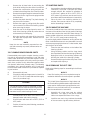
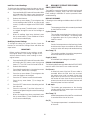
When Using Bag Connection
System (BCS) with One or Two
Bags (optional kit):
When connecting one or two
bags, the manifold adapters
must be installed closest to the
manifold outlet and the manifold
plug(s) must be placed farthest
from the manifold outlet.
1. Connect 3/8” (9,5mm) ID
plastic food grade tubing
to a bag adapter. Secure
with hose clamps.
2. Slide the hose clip
over the free end of
the tubing. Attach the
free end of the tubing
to a manifold adapter.
Secure with a large hose
clamp.
3. Push the manifold
adapter with spring and
valve into the left port
(nearest the manifold
outlet) of the mix inlet
manifold and secure
with retaining clip. (See
Figure 2-4).
4. If using two mix bags,
repeat steps 1 to 3 for
the middle port.
5. Install a manifold plug
into each empty inlet and
secure with a retaining
clip.
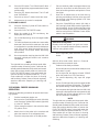
Figure 2-4 Bag Connection System (Optional)
Bag Adapter
Manifold
Adapter
Retaining
Clip
Mix Inlet
Manifold
Manifold
Plug
6. Place the mix bag(s) into the mix container.
7. Connect the bag adapter attached to the left side
of the manifold (closest to the mix outlet) to the
mix bag in the back of the mix container.
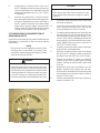
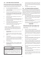
C. MIX LOW LEVEL INDICATOR ADJUSTMENT
The sensitivity of the “Mix Low” indication can be adjusted
to operator preference. If more advanced notice of low mix
is required, loosen the black adjustment knobs located on
the sensor brackets at the back of the machine cabinet
and slide the bracket upwards. If the “Mix Low” message
(right side) or fl ashing light (left side) appears while there
is still suffi cient mix in the container, slide the bracket
downward. Be sure to tighten the adjustment knobs after
properly positioning the sensor.

7
SECTION 3
INITIAL SET-UP AND OPERATION
3.1 OPERATOR’S SAFETY PRECAUTIONS
SAFE OPERATION IS NO ACCIDENT; observe these
rules:
A. Know the machine. Read and understand the
Operating Instructions.
B. Notice all warning labels on the machine.
C. Wear proper clothing. Avoid loose fi tting garments,
and remove watches, rings or jewelry that could
cause a serious accident.
D. Maintain a clean work area. Avoid accidents by
cleaning up the area and keeping it clean.
E. Stay alert at all times. Know which switch, push
button or control you are about to use and what
effect it is going to have.
F. Disconnect power for maintenance. Never
attempt to repair or perform maintenance on the
machine until the main electrical power has been
disconnected.
G. Do not operate under unsafe operating conditions.
Never operate the machine if unusual or excessive
noise or vibration occurs.
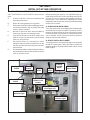
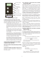
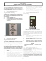
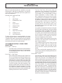
3.2 OPERATING CONTROLS AND INDICATORS
Before operating the machine, it is required that the op-
erator know the function of each operating control. Refer
to Figure 3-1 for the location of the operating controls on
the machine. For the information regarding error codes
displayed on the control panel, refer to the troubleshooting
section of this manual.
A. PUMP SWITCH (BOTH SIDES)
The pump motor switch is the toggle switch located under
the header panel. When the switch is placed in the OFF
position, the pump will not run. When the switch is placed
in the ON position, the pump will run until the preset pres-
sure is reached. It then cycles on and off as product is
drawn to maintain that pressure.
B. SPIGOT SWITCH (BOTH SIDES)
The spigot switch is mounted to the spigot cam assembly
behind the header panel. When the spigot is opened to
dispense product, the spigot switch opens and the “Serve
Mode” begins.
Figure 3-1 SU444 Freezer Controls
Cab Off
Indicator Light
Freezing
Cylinder
Off/On
IntelliTec Control
(See Figure 3-2)
Pump
Off/On
Pump
Off/On
Freezing
Switch
Standby/Serve
Switch
Clean/Off/Serve
Switch
Mix Low
Indicator Light
Main Freezer
Power Off/On
Blender Power
Off/On Circuit
Breaker

8
C. FRONT DOOR SAFETY SWITCH (BOTH SIDES)
The front door safety switch prevents the auger from turn-
ing when the front door is removed. The switch is open
when the door is removed and closed when the door is
properly installed.
D. DRIVE MOTOR OVERLOAD (BOTH SIDES)
The drive motor overload will trip if the drive motor is
overloaded. Single phase machines have an internal
overload and three phase machines have an external
overload. The overload will reset after approximately 10-
12 minutes. If the drive motor continues to trip, refer to
the Troubleshooting Section.
E. DISPENSE RATE ADJUSTOR (LEFT SIDE)
The dispense rate adjustor is located under the header
panel, to the immediate right of each spigot handle. Turning
the knob counterclockwise will decrease the dispense rate.
F. CLEAN/OFF/SERVE SWITCH (LEFT SIDE)
The CLEAN-OFF-SERVE switch is a three position toggle
switch used to control the operation of the refrigeration
system and auger. When the switch is placed in the
CLEAN position, the refrigeration system will be off and
auger will rotate for cleaning. When the switch is placed
in the OFF position, the refrigeration system and auger
will not operate. When the switch is placed in the SERVE
position, the refrigeration system and auger will operate
automatically. The switch should be placed in the SERVE
position for normal operation.
G. STANDBY/SERVE SWITCH (LEFT SIDE)
The standby/serve switch is a two position toggle switch.
When the switch is placed in the standby position the
machine will cycle to maintain a temperature below 41°F
(-15°C). When the switch is in the Serve position the ma-
chine will cycle to maintain a servable product.
H. FREEZING SWITCH (LEFT SIDE)
The freezing switch is a two position toggle switch. When
the switch is placed in the MAXIMUM position the machine
will be forced to run 30 seconds after the spigot is closed
if the temperature control is satisfi ed.
I. LOW MIX LIGHT (LEFT SIDE)
The low mix light will illuminate when the liquid level in
the mix container drops below the mix low level indicator.
(To adjust the indicator see Section 2.6 C.)
J. MAIN FREEZER POWER SWITCH (RIGHT SIDE)
The Main Freezer Power switch is a two position rocker
switch that supplies power to the IntelliTec control, the
right freezing cylinder circuits and the cabinet refrigeration
system. When the switch is placed in the ON position,
the cabinet refrigeration system will run until the preset
temperature is reached; then it will cycle ON and OFF to
maintain that temperature. Power to the right side freezing
cylinder can then be controlled with the Freezing Cylinder
OFF/ON switch.
K. FREEZING CYLINDER OFF/ON SWITCH (RIGHT
SIDE)
The Freezing Cylinder OFF/ON switch is a two position
toggle switch used to supply power to the right freezing
cylinder control circuit. When the switch is in the OFF
position, the freezing cylinder’s refrigeration system and
auger will not operate. When the switch is in the ON posi-
tion, the machine will be operational.
L. BLENDER POWER OFF/ON AND CIRCUIT BREAKER
SWITCH (RIGHT SIDE - SU444 ONLY)
The Blender Power Off/On and Circuit Breaker switch is
a two position toggle switch used to supply power to the
blender. When the switch is in the OFF position, there is
no power to the blender. When the switch is in the ON
position, the blender will operate any time the spigot
handle is pushed to the right. This switch also serves as
a circuit breaker to interrupt power if the rotation of the
blender agitator becomes hindered.
M. CAB OFF INDICATOR LIGHT (RIGHT SIDE)
A fl ashing light indicates the Main Freezer Power Switch
is in the OFF position; no refrigeration is being supplied
to the cab. Place the Main Freezer Power switch in the
ON position for cab refrigeration.
N. PUSH TO FREEZE BUTTON (RIGHT SIDE)
The PUSH TO FREEZE button is a snap switch used to
initiate “Serve Mode”.
NOTE
After the PUSH TO FREEZE button is pressed,
the drive motor starts. After a 3-second delay, the
compressor will start.
O. LEDS (RIGHT SIDE)
The membrane switch (touchpad) features two lights: a
green LED and an amber LED. The green LED is lit dur-
ing “Serve Mode”. During freeze down, it is not lit. When
product consistency approaches 75% in the freezing
cylinder, the green LED fl ashes. The amber LED is on
during all other modes. Both LEDs alternatively fl ash if
an error occurs or if the freezing cylinder is off.
P. CLEAN BUTTON (RIGHT SIDE)
The CLEAN button is a snap switch. When the button is
pressed, the freezing cycle stops and the drive motor will
start. A CLEAN message will display on the LCD screen
along with a 5-minute countdown timer. To exit the CLEAN
mode, turn the Freezing Cylinder OFF/ON switch to the
OFF position or press the CLEAN button again. If the
machine is left in CLEAN for more than 20 minutes, an
error code (E4) will be displayed on the display panel.
Place the Freezing Cylinder OFF/ON switch in the OFF
position and back in the ON position to clear this error.
Q. MIX LOW LIGHT INDICATOR (RIGHT SIDE)
A MIX LOW message will appear on the LCD display to
alert the operator of a low mix condition. The message
will display when there is approximately one gallon of mix
left in the mix container. When the MIX LOW message is
displayed, refi ll the container or replace a bag immediately.

9
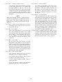
R. MENU NAVIGATION BUTTONS (RIGHT SIDE)
The Menu Navigation Buttons allow the user to display
information regarding the machine’s status of operation
as well as adjust product consistency (Fig. 3-2).
Selection Button (SEL) The SEL button is used in
combination with the left arrow button to enter into
the settings of the IntelliTec control. This button is
also used to navigate through the control settings
menu.
Set Button (SET) The SET button is used to save
a change made to the product consistency setting.
It is also used to save changes when modifying
control settings.
Left Arrow Button () If the left arrow button is
pressed for 5 seconds, the display will remain lit.
To turn the light off, press the left arrow button for
5 seconds. The left arrow button is used primarily
to navigate through the control settings.
Up Arrow Button () After pressing the SET button,
the up arrow button will change the value of the
product consistency setting. This button is used
primarily to navigate through the control settings.
3.3 IMPORTANT INFORMATION REGARDING
CLEANING AND SANITIZING
Soft serve and shake machines require special consider-
ation when it comes to food safety and proper cleaning
and sanitizing.
The following information specifi cally covers issues for
cleaning and sanitizing frozen dessert machines. This
information is meant to supplement a comprehensive
food safety program.
SOIL MATERIALS ASSOCIATED WITH FROZEN
DESSERT MACHINES
MILKFAT/BUTTERFAT – As components of ice-cream/
frozen custard mix, these soils will accumulate on the
interior surfaces of the machine and its parts. Fats are
diffi cult to remove and help attribute to milkstone buildup.
MILKSTONE – Is a white/gray fi lm that forms on equip-
ment and utensils that are exposed to dairy products.
These fi lms will accumulate slowly on surfaces because of
ineffective cleaning, use of hard water, or both. Milkstone
is usually a porous deposit, which will harbor microbial
contaminants and eventually defy sanitizing efforts.
Once milkstone has formed, it is very diffi cult to remove.
Without using the correct product and procedure, it is
nearly impossible to remove a thick layer of milkstone.
(NOTE: general-purpose cleaners DO NOT remove
milkstone.) This can lead to high bacteria counts and a
food safety dilemma.
IT IS BEST TO CONTROL MILKSTONE ON A DAILY BA-
SIS BEFORE IT CAN BECOME A SIGNIFICANT FOOD
SAFETY PROBLEM.
In addition to food safety, milkstone can cause prema-
ture wear to machine parts, which can add to costs for
replacement parts or possibly more expensive repairs
if worn machine parts are not replaced once they have
become excessively worn.
IMPORTANT DIFFERENCES BETWEEN CLEANING
AND SANITIZING
CLEANING vs. SANITIZING
It is important to distinguish between cleaning and sanitiz-
ing. Although these terms may sound synonymous, they
are not. BOTH are required for adequate food safety and
proper machine maintenance.
CLEANING
· Is the removal of soil materials from a surface.
· Is a prerequisite for effective sanitizing.
NOTE
An UNCLEAN surface will harbor bacteria that can
defy sanitizing efforts.
Bacteria can develop and resist sanitizing efforts within
a layer of soil material (milkstone). Thorough cleaning
procedures that involve milkstone removal are critical for
operators of frozen dessert machines.
SANITIZING
· Kills bacteria.
· Can be effective on clean surfaces only.
NOTE
Using a SANITIZER on an unclean surface will not
guarantee a clean and safe frozen dessert machine.
Figure 3-2 IntelliTec Control
Push to Freeze
Green LED
Amber LED
SEL Button
SET Button
Purge/Clean
Button
Up Arrow Button
Left Arrow Button

10
With proper daily use of STERA-SHEEN or its equivalent,
there is no need for the use of a DELIMER.
DO NOT USE BLEACH
· BLEACH HAS ABSOLUTELY NO CLEANING
PROPERTIES.
· BLEACH IS CORROSIVE. It will damage
components of the machine causing premature
wear and metal corrosion.
GENERAL PURPOSE CLEANERS
General purpose cleaners do not have the ability to re-
move milkstone. Milkstone will become a problem if not
remedied with additional products and procedures.
THE USE OF CHLORINE TEST STRIPS
“Test strips” are used to determine concentrations of
active chlorine in sanitizing solutions. To use the strips,
tear off a small portion and submerge it into the sanitizing
solution. Then, compare the color change to the color key
on the side of the test strip dispenser to determine the
approximate chlorine concentration.
The ideal concentration of chlorine needs to be 100 ppm
(as stated by the FDA).
NOTE
Follow the directions on the container for proper
concentration.
Two main factors contribute to falling chlorine concentra-
tions in a sanitizing solution.
1. PRODUCT USE – As the chlorine in the solution
is being used, chlorine concentrations fall.
2. TIME – As time passes, small amounts of chlorine
“evaporate” from the solution. (That is why you
can smell it.)
Sanitizing solutions should not be allowed to fall below
100 ppm chlorine. New solutions should be mixed once
old solutions become ineffective.
3.4 DISASSEMBLY OF LEFT SIDE
WARNING
Moving machinery can grab, mangle and dis-
member. Place the Clean/Off/Serve switch in the
OFF position before disassembling for cleaning or
servicing.
Before using the machine for the fi rst time, complete
machine disassembly, cleaning and sanitizing proce-
dures need to be followed. Routine cleaning intervals
and procedures must comply with the local and state
health codes. Inspection for worn or broken parts should
be made at every disassembly of the machine. All worn
or broken parts should be replaced to ensure safety to
both the operator and the customer and to maintain good
machine performance and a quality product.
To disassemble the left side, refer to the following steps:
PROPER DAILY MAINTENANCE:
The Only Way to Assure Food Safety and Product Quality
Proper daily maintenance can involve a wide variety
of products and procedures. Overall, the products and
procedures fall into three separate categories. (Please
note that this is a brief overview intended for informational
purposes only.)
1. CLEANING – This involves draining mix from
the freezing cylinder and rinsing the machine
with water. Next, a cleaner is run through the
machine. Then, the machine is disassembled
and removable parts are taken to the sink for
cleaning.
2. MILKSTONE REMOVAL – Since most cleaners
do not have the ability to remove milkstone, the
use of a delimer becomes necessary. Although
this procedure may not be needed on a daily
basis, it will usually follow the cleaning procedure.
It requires letting a delimer solution soak in the
machine for an extended period. Individual parts
are also soaked in a deliming solution for an
extended period of time (more about delimers in
Additional Information).
3. SANITIZING – After the machine has been
cleaned and contains no milkstone, the machine
is reassembled. Then a FDA-approved sanitizing
solution is run through the machine to kill bacteria.
The machine is then ready for food preparation.
As a recommended cleaner and sanitizer for your frozen
dessert machine, STERA-SHEEN has proven to be one
of the best daily maintenance products for:
· CLEANING – Thorough removal of all solids
including butterfat and milk fat.
· MILKSTONE REMOVAL – Complete removal of
milkstone.
· SANITIZING – FDA-approved no rinse sanitizer
for food contact surfaces.
ADDITIONAL INFORMATION
THE USE OF DELIMERS
A delimer is a strong acid that has the ability to dissolve
milkstone. This type of chemical may become necessary
once high levels of milkstone have developed. While these
products are very effective for removing HIGH levels of
milkstone, they are not ideal for two reasons:
1. PRODUCT SAFETY – Strong acids are dangerous
chemicals. Carefully follow safety instructions
provided with delimer products.
2. MACHINE DAMAGE – Strong acids will attack
metal and rubber causing premature wear of
parts. The use of a delimer needs to be closely
monitored to avoid damage to machine surfaces
and parts.

11
Before using the machine for the fi rst time, complete
machine disassembly, cleaning and sanitizing proce-
dures need to be followed. Routine cleaning intervals
and procedures must comply with the local and state
health codes. Inspection for worn or broken parts should
be made at every disassembly of the machine. All worn
or broken parts should be replaced to ensure safety to
both the operator and the customer and to maintain good
machine performance and a quality product.
To disassemble the machine, refer to the following steps:
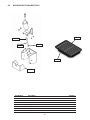
A. REMOVE BLENDER (SU444 ONLY)
1. Make sure the Main Freezer Power Off/On switch
is in the OFF position.
2. Unplug the blender.
3. Remove the blender agitator by holding the blender
shaft and turning the agitator counterclockwise.
Remove the blender shaft by holding the blender
collar and turning the shaft counterclockwise.
(Figure 3-3)
4. Loosen knobs holding the blender splash shield
bracket in place and remove the bracket.
5. Remove the knobs on the front door. Remove
the blender assembly and set aside.
NOTE
Support the blender with one hand while removing
the knobs on the door to prevent the blender from
dropping.
B. REMOVE FRONT DOOR AND AUGER
1. Make sure the Main Freezer Power Off/On switch
is in the OFF position
2. Remove the knobs on the front door and remove
the door by pulling it off the studs.
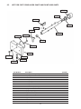
A. REMOVE FRONT DOOR AND AUGER
1. Make sure the Clean/Off/Serve switch is in the
OFF position
2. Remove the knobs on the front door and remove
the door by pulling it off the studs.
3. Remove the air bleed valve by unscrewing the
knob while holding the valve stem from behind.
Remove the compression spring and push the
air bleed valve through the rear of the front door.
4. Remove the spigot through the bottom of the front
door. Remove all o-rings from the spigot and the
air bleed valve.
5. Remove the front auger support and plastic
bearing.
6. Remove the auger by pulling slowly and rotating
out of the machine barrel. As the auger is
withdrawn, remove each plastic fl ight and spring
from the auger. Be careful not to scratch inside of
machine barrel when removing fl ights or auger.
Remove the spring from each auger fl ight.
7. Keep the rear of the auger tipped up once it is
clear of the freezing cylinder to prevent the rear
seal assembly from dropping.
8. Wipe the spline lubricant off the hex end of the
auger with a paper towel. Remove the rear seal
assembly.
NOTE
Keep the rear seal assembly separate from the
right side assembly to prevent problems when as-
sembling.
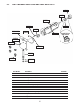
3.5 DISASSEMBLY OF RIGHT SIDE
WARNING
Moving machinery can grab, mangle and dismem-
ber. Place the Main Freezer Power Off/On switch in
the OFF position before disassembling for cleaning
or servicing.
Figure 3-2 Left Side Front Door
Figure 3-3 SU444 Blender Agitator Assembly
Shaft
Agitator
Collar

12
3. Remove the air bleed valve by unscrewing the
knob while holding the valve stem from behind.
Remove the compression spring and push the
air bleed valve through the rear of the front door.
4. Remove the spigot through the bottom of the front
door. Remove all o-rings from the spigot and the
air bleed valve.
5. Remove the plastic bearing. The plastic bearing
may be on the front door.
6. Remove the auger by pulling slowly. Be careful
not to scratch the inside of the freezing cylinder
when removing the auger.
7. Keep the rear of the auger tipped up once it is
clear of the freezing cylinder to prevent the rear
seal assembly from dropping.
8. Wipe the hex drive anti-seize off the hex end of
the auger with a paper towel. Remove the rear
seal assembly.
NOTE
Keep the rear seal assembly separate from the
right side assembly to prevent problems when as-
sembling.
3.6 CLEANING DISASSEMBLED PARTS
Disassembled parts require complete cleaning, sanitiz-
ing and air drying before assembling. Local and state
health codes will dictate the procedure required. Some
state health codes require a four sink process (pre-wash,
wash, rinse, sanitize, air dry), while others require a three
sink process (without the pre-wash step). The following
procedures are a general guideline only. Consult your
local and state health codes for the procedures required
in your location.
A. Disassemble all parts.
B. Place all front door and auger parts in clean 90° to
110°F (32°C to 43°C) water and wash thoroughly
(four sink procedure only).
CAUTION
The blender motor cannot be immersed in water
or sanitizer. Wash the motor and mounting bracket
with a mild detergent solution taking care not to al-
low water into the motor bearings or seals.
C. Place all parts in 90° to 110°F (32°C to 43°C) mild
detergent water and wash thoroughly.
D. Rinse all parts with clean 90° to 110°F (32°C to
43°C) water.
E. Sanitize all machine parts following procedures
outlined below.
3.7 SANITIZING PARTS
A. Use a sanitizer, mixed according to manufacturer’s
instructions, to provide a 100 parts per million
strength solution. Mix sanitizer in quantities of
no less than 2 gallons of 90° to 110°F (32°C to
43°C) water. Any sanitizer must be used only in
accordance with the manufacturer’s instructions.
B. Place all parts in the sanitizing solution for 5
minutes, then remove and let air dry completely
before assembling in machine.
3.8 CLEANING THE MACHINE
The exterior should be kept clean at all times to preserve
the luster of the stainless steel. A high grade of stainless
steel has been used on the machine to ease cleanup. To
remove spilled or dried mix, wash the exterior with 90° to
110°F (32°C to 43°C) soapy water and wipe dry.
Do not use highly abrasive materials, as they will mar the
fi nish. A mild alkaline cleaner is recommended. Use a soft
cloth or sponge to apply the cleaner. For best results, wipe
with the grain of the steel.
A. Clean the rear seal surfaces on the inside of the
freezing cylinders.
B. Using sanitizing solution and the large barrel
brush provided, sanitize the freezing cylinders by
dipping the brush in the sanitizing solution and
brushing the inside of the freezing cylinders.
C. Remove the drip trays from the front panel. Clean
and replace the drip trays.
3.9 ASSEMBLING THE LEFT SIDE
Refer to the following steps for assembling the left freez-
ing cylinder:
NOTICE
Petrol-Gel sanitary lubricant or equivalent must be
used when lubrication of machine parts is specifi ed.
NOTICE
The United States Department of Agriculture and
the Food and Drug Administration require that lubri-
cants used on food processing equipment be certi-
fi ed for this use. Use lubricants only in accordance
with the manufacturer’s instructions.
A. Assemble all o-rings onto parts dry, without
lubrication. Then apply a thin fi lm of sanitary
lubricant to exposed surfaces of the o-rings.
B. Install the rear seal o-ring. Lubricate the outside
of the rear seal o-ring with sanitary lubricant.

13
C. Install the stainless steel rear seal adapter into
the rear seal dry (without lubricant). Lubricate
the inside surface of the rear seal adapter and
install it onto the auger shaft. DO NOT lubricate
the outside of the rear auger seal (Fig. 3-4).
NOTE
Make sure to install the correct rear seal adapter
onto the auger. The front door will not close if the
right side rear seal adapter is installed onto the left
side auger.
D. Lubricate the hex drive end of the auger with a
small amount of spline lubricant. A small container
of anti seize is shipped with the machine.
E. Screw the springs onto the studs in the plastic
fl ights. The springs must be screwed into the
fl ights completely to provide proper compression.
F. Install the two plastic fl ights onto the rear of the
auger and insert it part way into the freezing
cylinder.
G. Install the remaining plastic fl ights, push the auger
into the freezing cylinder and rotate slowly until
the auger engages the drive shaft.
H. Apply a thin layer of sanitary lubricant to the inside
and outside of the auger support bushing. Install
the bushing onto the auger support and install the
auger support into the front of the auger. Rotate
the auger support so that one leg of the support
points straight up.
I. Assemble the air bleed valve o-ring onto the air
bleed valve. Position the o-ring into the groove
close to the wide part. Apply a thin fi lm of sanitary
lubricant to the o-ring.
J. Insert the air bleed valve into the back of the front
door. Install the compression spring onto the air
bleed valve then screw the knob on fi nger tight.
K. Apply a thin layer of sanitary lubricant to the
o-rings on the spigot body and install the spigot
body through the bottom of the front door.
L. Place the front door assembly on the mounting
studs and the push front door against the machine
carefully.
M. Secure the front door to the machine by placing
the knobs on the studs and tightening until fi nger
tight. Do not overtighten. Proper o-ring seal can
be observed through the transparent front door.
3.10 ASSEMBLING THE RIGHT SIDE
Refer to the following steps for assembling the right
freezing cylinder:
NOTICE
Petrol-Gel sanitary lubricant or equivalent must be
used when lubrication of machine parts is specifi ed.
NOTICE
The United States Department of Agriculture and
the Food and Drug Administration require that lubri-
cants used on food processing equipment be certi-
fi ed for this use. Use lubricants only in accordance
with the manufacturer’s instructions.
A. Assemble all o-rings onto parts dry, without
lubrication. Then apply a thin fi lm of sanitary
lubricant to exposed surfaces of the o-rings.
B. Install the rear seal o-ring. Lubricate the outside
of the rear seal o-ring with sanitary lubricant.
C. Install the stainless steel rear seal adapter into
the rear seal dry (without lubricant). Lubricate the
inside surface of the rear seal adapter, including
the adapter o-ring, and install it onto the auger
shaft. DO NOT lubricate the outside of the rear
auger seal.
NOTE
Make sure to install the correct rear seal adapter
onto the auger. The back of the cylinder will leak if
the left side rear seal adapter is installed onto the
right side auger.
D. Lubricate the hex drive end of the auger with a
small amount of spline lubricant. A small container
of anti seize is shipped with the machine.
E. Install the plastic scraper blades onto the auger
and insert the auger into the freezing cylinder.
F. Rotate the auger until it engages the drive shaft.
G. Assemble the air bleed valve o-ring onto the air
bleed valve. Position the o-ring into the groove
close to the wide part. Apply a thin fi lm of sanitary
lubricant to the o-ring.
H. Insert the air bleed valve into the back of the front
door. Install the compression spring onto the air
bleed valve then screw the knob on fi nger tight.
I. Install the spigot through the bottom of the front
door.
J. Apply a thin fi lm of sanitary lubricant to the inside
and outside of the plastic bearing, then place it
into the front door.
Figure 3-4 Rear Seal Assembly
Hex Drive
Anti Seize
Petrol-Gel

14
K. Place the front door assembly on the mounting
studs and the push front door against the machine
carefully.
L. On the SU444, place the blender assembly onto
the front door studs.
M. Secure the front door to the machine by placing
the knobs on the studs and alternately tightening
opposite corners until finger tight. Do not
overtighten. Proper o-ring seal can be observed
through the transparent front door.
N. On the SU444, attach the blender shroud to the
blender assembly. The blender shroud has a pin
that needs to be properly aligned with the machine
safety switch.
3.11 SANITIZING
Sanitizing must be done after the machine is clean and
just before the machine is fi lled with mix. Sanitizing the
night before is not effective. However, you should always
clean the machine and parts after using it.
NOTE
The United States Department of Agriculture and
the Food and Drug Administration require that all
cleaning and sanitizing solutions used with food
processing equipment be certifi ed for this use.
When sanitizing the machine, refer to local sanitary regu-
lations for applicable codes and recommended sanitizing
products and procedures. The frequency of sanitizing
must comply with local health regulations. Mix sanitizer
according to manufacturer’s instructions to provide a 100
parts per million strength solution. Mix sanitizer in quanti-
ties of no less than 2 gallons of 90°F to 110°F (32°C to
43°C) water. Allow sanitizer to contact the surfaces to be
sanitized for 5 minutes. Any sanitizer must be used only
in accordance with the manufacturer’s instructions.
CAUTION
Risk of Product Damage
Avoid prolonged contact of sanitizer with machine
parts. Sanitizer may cause corrosion of stainless
steel parts if there is prolonged contact.
SANITIZING THE LEFT SIDE
A. Prepare 3 gallons of sanitizing solution following
manufacturer’s instructions, and pour into storage
container.
B. Place the mix pump switch in the ON position and
open air bleed valve on the front door by pushing
valve in and holding.
C. Let sanitizing solution fi ll the machine barrel to
air bleed valve, then close the valve by pulling
out to lock in place.
D. Place the CLEAN-OFF-SERVE toggle switch in
the CLEAN position.
E. Check for leaks when the machine barrel is fi rst
pressurized with sanitizing solution.
1. Check for leaks at the plastic front door, the
O-rings may not be sealed.
2. Check the drain located at the center of the
Drip Tray for leaks coming from the rear of the
Rear Auger Seal.
3. Check inside cab unit for leaks at hose
connections.
F. Using a sanitized soft bristle brush or equivalent,
dipped in sanitizing solution, clean mix container.
G. After fi ve minutes, open spigot to drain sanitizing
solution.
H. Empty any remaining sanitizing solution from the
mix container.
H. Close the spigot and place the mix pump switch
and the CLEAN-OFF-SERVE switch in the OFF
position.
SANITIZING THE RIGHT SIDE
A. Prepare 3 gallons of sanitizing solution following
the manufacturer’s instructions. Pour it into a
clean container and place the container into the
cabinet.
B. Place the mix pump switch in the ON position
and open the air bleed valve on the front door
by pushing the valve in and holding.
C. Let sanitizing solution fi ll the freezing cylinder to
the air bleed valve. Close the valve by pulling it
out to lock it into place.
D. Place the Main Freezer Power OFF/ON and
Freezing Cylinder OFF/ON switches in the ON
position. Press the CLEAN button.
E. Check for leaks when the freezing cylinder is fi rst
pressurized with sanitizing solution.
1. Check for leaks at the front door seals.
2. Check the drain tray located in the side panel
for leaks coming from the rear of the rear auger
seal.
3. Check the inside of the cab unit for leaks at
the hose connections.
F. Using a sanitized soft bristle brush (or equivalent)
dipped in sanitizing solution, clean the mix
container.
G. After fi ve minutes, open the spigot to drain the
sanitizing solution.
H. Empty any remaining sanitizing solution from the
mix container.
Page is loading ...
Page is loading ...
Page is loading ...
Page is loading ...
Page is loading ...
Page is loading ...
Page is loading ...
Page is loading ...
Page is loading ...
Page is loading ...
Page is loading ...
Page is loading ...
Page is loading ...
Page is loading ...
Page is loading ...
Page is loading ...
Page is loading ...
Page is loading ...
Page is loading ...
Page is loading ...
Page is loading ...
Page is loading ...
Page is loading ...
Page is loading ...
Page is loading ...
-
 1
1
-
 2
2
-
 3
3
-
 4
4
-
 5
5
-
 6
6
-
 7
7
-
 8
8
-
 9
9
-
 10
10
-
 11
11
-
 12
12
-
 13
13
-
 14
14
-
 15
15
-
 16
16
-
 17
17
-
 18
18
-
 19
19
-
 20
20
-
 21
21
-
 22
22
-
 23
23
-
 24
24
-
 25
25
-
 26
26
-
 27
27
-
 28
28
-
 29
29
-
 30
30
-
 31
31
-
 32
32
-
 33
33
-
 34
34
-
 35
35
-
 36
36
-
 37
37
-
 38
38
-
 39
39
-
 40
40
-
 41
41
-
 42
42
-
 43
43
-
 44
44
-
 45
45


Stoelting SU444 Air Cooled User manual
- Type
- User manual
- This manual is also suitable for
Ask a question and I''ll find the answer in the document
Finding information in a document is now easier with AI
Related papers
-
Stoelting O212 User manual
-
-
-
-
-
-
-
-
-
Other documents
-
 RTS Home Accents 55100001007981 Installation guide
-
 EarthMinded F-RN096 Installation guide
-
Bartscher 100331 Operating instructions
-
MULTIPLEX Beermaster Air CO2 Kit Installation guide
-
Omega Engineering FPU5-MT-110 User manual
-
-
Crathco / Grindmaster 5711 User manual
-
Server FP-200 User manual
-
Grindmaster 5311 User manual
-
Vollrath Soft Serve Freezer, Countertop, Mini User manual

