Page is loading ...

Model SO212
OPERATORS MANUAL
Manual No. 513610 Rev.2


This manual provides basic information about the machine. Instructions and suggestions are
given covering its operation and care.
The illustrations and specifi cations are not binding in detail. We reserve the right to make
changes to the machine without notice, and without incurring any obligation to modify or pro-
vide new parts for machines built prior to date of change.
DO NOT ATTEMPT to operate the machine until instructions and safety precautions in this
manual are read completely and are thoroughly understood. If problems develop or questions
arise in connection with installation, operation, or servicing of the machine, contact Stoelting.
Stoelting Foodservice Equipment
502 Highway 67
Kiel, WI 53042-1600
U.S.A.
Main Tel: 800.558.5807
Fax: 920.894.7029
Customer Service: 888.429.5920
Fax: 800.545.0662
Email: [email protected]
© 2014 PW Stoelting, LLC
stoeltingfoodservice.com

Safety Alert Symbol:
This symbol Indicates danger, warning or caution.
Attention is required in order to avoid serious per-
sonal injury. The message that follows the symbol
contains important information about safety.
Signal Word:
Signal words are distinctive words used throughout
this manual that alert the reader to the existence and
relative degree of a hazard.
CAUTION
The signal word “CAUTION” indicates a potentially
hazardous situation, which, if not avoided, may result
in minor or moderate injury and equipment/property
damage.
A Few Words About Safety
Safety Information
Read and understand the entire manual before
operating or maintaining Stoelting equipment.
This manual provides the operator with information
for the safe operation and maintenance of Stoelting
equipment. As with any machine, there are hazards
associated with their operation. For this reason safety
is emphasized throughout the manual. To highlight
specifi c safety information, the following safety defi ni-
tions are provided to assist the reader.
The purpose of safety symbols is to attract your at-
tention to possible dangers. The safety symbols, and
their explanations, deserve your careful attention
and understanding. The safety warnings do not by
themselves eliminate any danger. The instructions
or warnings they give are not substitutes for proper
accident prevention measures.
If you need to replace a part, use genuine Stoelting
parts with the correct part number or an equivalent
part. We strongly recommend that you do not use
replacement parts of inferior quality.
WARNING
The signal word “WARNING” indicates a potentially
hazardous situation, which, if not avoided, may result
in death or serious injury and equipment/property
damage.
CAUTION
The signal word “CAUTION” not preceded by the
safety alert symbol indicates a potentially hazardous
situation, which, if not avoided, may result in equip-
ment/property damage.
NOTE (or NOTICE)
The signal word “NOTICE” indicates information or
procedures that relate directly or indirectly to the
safety of personnel or equipment/property.

SECTION DESCRIPTION PAGE
1. INTRODUCTION
1.1 Description............................................................................................................. 1
1.2 Specifications ........................................................................................................ 2
2. INSTALLATION INSTRUCTIONS
2.1 Safety Precautions ................................................................................................. 3
2.2 Shipment and Transit.............................................................................................. 4
2.3 Freezer Installation ................................................................................................. 4
2.4 Installing Permanent Wiring .................................................................................... 5
3. INITIAL SET-UP AND OPERATION
3.1 Operator's Safety Precautions................................................................................ 7
3.2 Operating Controls and Indicators........................................................................... 7
3.3 Sanitizing ............................................................................................................... 8
3.4 Freeze Down and Operation................................................................................... 9
3.5 Mix Information ....................................................................................................... 10
3.6 Removing Mix From Freezer .................................................................................. 10
3.7 Cleaning The Freezer............................................................................................. 11
3.8 Disassembly of Freezer Parts ................................................................................ 11
3.9 Cleaning The Freezer Parts.................................................................................... 12
3.10 Sanitize Freezer and Freezer Parts ....................................................................... 12
3.11 Assembly of Freezer ............................................................................................. 13
3.12 Routine Cleaning ................................................................................................... 13
3.13 Preventive Maintenance ........................................................................................ 15
3.14 Extended Storage ................................................................................................. 15
4. TROUBLESHOOTING................................................................................................ 19
5. REFERENCE DRAWINGS......................................................................................... 19
TABLE OF CONTENTS

LIST OF ILLUSTRATIONS
FIGURE TITLE PAGE
1-1 Model SO212 Freezer............................................................................................ 1
1-2 Specifications ........................................................................................................ 1
2-1 Warning Label Locations ....................................................................................... 3
2-2 Leveling ................................................................................................................. 4
2-3 Space and Ventilation Requirements ..................................................................... 4
2-4 Electrical Plug ....................................................................................................... 4
2-5 Power Cord Connection ......................................................................................... 5
3-1 Controls ................................................................................................................. 7
3-2 Mix Inlet Regulator ................................................................................................. 9
3-3 Sanitizing Hopper .................................................................................................. 9
3-4 Dispensing Product ...............................................................................................10
3-5 Removing Blender ..................................................................................................11
3-6 Removing Auger Shaft ...........................................................................................12
3-7 Removing O-Ring ...................................................................................................12
3-8 Cleaning Freezer Barrel .........................................................................................12
3-9 Auger and Door Assembly .....................................................................................13
5-1 Replacement Parts ................................................................................................19

1
1.1 DESCRIPTION
The Stoelting SO212 floor model freezer is gravity fed.
The freezer is equipped with fully automatic controls to
provide a uniform product. The freezer is designed to
operate with almost any type of commercial shake mix
available. This manual is designed to assist qualified
service personnel and operators in the installation, opera-
tion and maintenance of the Stoelting Model SO212
freezer.
SECTION 1
DESCRIPTION AND SPECIFICATIONS
Figure 1-1 Model SO212 Freezer
Figure 1-2 Specifications

2
MODEL SO212
FLOOR MODEL
GRAVITY SHAKE FREEZER
1.2 SPECIFICATIONS
DIMENSIONS:
Freezer: 17.6" (45cm) wide x 28.6" (73cm) deep x 63.75" (162cm) high
Crated: 19.5" (50cm) wide x 33" (84cm) deep x 40" (102cm) high
WEIGHT:
Freezer: 332 lbs. (150kg) Crated: 427 lbs. (193kg)
ELECTRICAL:
Description SO212-38
Voltage AC 1 PH 208/230
Total Run Amps 10.5
Drive Motor 3/4 HP
Compressor 12,000 BTUH (90°F - 0°F)
Use 20 amp HACR circuit breaker.
Automatic safeguard circuit built into electronic control - protects major freezer components under abnormal
operating conditions.
COOLING:
Air cooled requires minimum 3" (7.6cm) air clearance on back side.
No clearance needed on sides.
HOPPER:
7 Gallons (26,5 liters) refrigerated and insulated.

3
2.1 SAFETY PRECAUTIONS
Do not attempt to operate the freezer until the safety
precautions and operating instructions in this manual are
read completely and are thoroughly understood.
Take notice of all warning labels on the freezer. The labels
have been put there to help maintain a safe working
environment. The labels have been designed to withstand
washing and cleaning. All labels must remain legible for
the life of the freezer. Labels should be checked periodi-
cally to be sure they can be recognized as warning labels.
SECTION 2
INSTALLATION INSTRUCTIONS
If danger, warning or caution labels are needed, indicate
the part number, type of label, location of label, and
quantity required along with your address and mail to:
STOELTING, INC.
ATTENTION: Customer Service
502 Hwy. 67
Kiel, Wisconsin 53042
Figure 2-1 Warning Label Locations

4
2.2 SHIPMENT AND TRANSIT
The freezer has been assembled, operated and inspected
at the factory. Upon arrival at the final destination, the
complete freezer must be checked for any damage which
may have occurred during transit.
With the method of packaging used, the freezer should
arrive in excellent condition. THE CARRIER IS RESPON-
SIBLE FOR ALL DAMAGE IN TRANSIT, WHETHER
VISIBLE OR CONCEALED. Do not pay the freight bill until
the freezer has been checked for damage. Have the
carrier note any visible damage on the freight bill. If
concealed damage and/or shortage is found later, advise
the carrier within 10 days and request inspection. The
customer must place claim for damages and/or shortages
in shipment with the carrier. Stoelting, Inc. cannot make
any claims against the carrier.
2.3 FREEZER INSTALLATION
Installation of the freezer involves moving the freezer
close to its permanent location, removing all crating,
setting in place, assembling parts, and cleaning.
A. Uncrate the freezer.
B. Accurate leveling is necessary for correct drainage
of freezer barrel and to insure correct overrun.
Place a level on top of the freezer at each corner
to check for level condition. If adjustment is
necessary, level the freezer by turning the caster
in or out and tighten the locknut. (Fig 2-2).
C. The freezer is equipped with an air cooled
condenser and requires correct ventilation. The
front of the freezer is the air intake and the back
discharge. Both front and back must have a
minimum of 3" of clearance. (Fig 2-3).
CAUTION
Failure to provide adequate ventilation will void war-
ranty.
D. Place the OFF-ON switch in the OFF position.
E. Connect the power cord. The plug is designed for
208 or 230 volt/20 amp duty. Check the nameplate
on your freezer for proper supply. The unit must
be connected to a properly grounded receptacle.
The electrical cord furnished as part of the freezer
has a three prong grounding type plug (Fig. 2-4).
The use of an extension cord is not recommended,
if necessary use one with a size 12 gauge or
heavier with ground wire. Do not use an adapter
to get around grounding requirement.
CAUTION
Do not alter or deform the plug in any way.
F. Install the drip tray, drain tray, hopper cover and
other miscellaneous parts on the freezer.
Figure 2-2 Leveling
Figure 2-3 Space and Ventilation Requirements
Figure 2-4 Electrical Plug

5
2.4 INSTALLING PERMANENT WIRING
If permanent wiring is required by local codes, the follow-
ing procedure must be performed.
WARNING
Disconnect freezer from the source of electrical
supply before servicing.
A. Remove the left side panel and electrical box
cover.
B. Disconnect the wires from the terminal block.
Disconnect the green ground wire from the
grounding stud. (Fig 2-5).
C. Remove the power cord.
D. Install permanent wiring according to local code.
E. Replace the electrical box cover and left side
panel.
Figure 2-5 Power Cord Connections

6

7
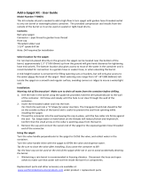
Figure 3-1 Controls
3.1 OPERATOR’S SAFETY PRECAUTIONS
Safe operation is no accident; observe these rules:
A. Know the freezer. Read and understand the
operating instructions.
B. Notice all warning labels on the freezer.
C. Wear proper clothing. Avoid loose fitting garments,
and remove watches, rings or jewelry which
could cause a serious accident.
D. Maintain a clean work area. Avoid accidents by
cleaning up the area and keeping it clean.
E. Stay alert at all times. Know which switch, button
or control you are about to use and what effect it
is going to have.
F. Disconnect electrical cord for maintenance. Never
attempt to repair or perform maintenance on the
freezer until the main electrical power has been
disconnected.
SECTION 3
INITIAL SETUP AND OPERATION
G. Do not operate under unsafe operating conditions.
Never operate the freezer if unusual or excessive
noise or vibration occurs.
3.2 OPERATING CONTROLS AND
INDICATORS
Before operating the freezer, it is required that the operator
know the function of each operating control. Refer to
Figure 3-1 for the location of the operating controls on the
freezer. For the information regarding flashing indicator
lights, refer to Section 4 - Troubleshooting.
WARNING
The Power OFF-ON switch must be placed in the
OFF position when disassembling for cleaning or
servicing. The freezer must be disconnected from
electrical supply before removing any access panel.
Mix Low
Indicator
CLEAN
Switch
PUSH TO FREEZE
Switch
Blender
Power Switch
Hold/Ready
Switch
Consistency/
Temperature
Adjustment
OFF-ON
Power Switch

8
A. SPIGOT SWITCH
The spigot switch will automatically activate the
auger drive and refrigeration systems when the
spigot is opened to dispense product (pulled
straight downwards). When the spigot is closed,
the drive motor and compressor will remain “on”
until the product in the barrel reaches the proper
temperature.
The spigot switch will also activate the blender
when pushed to the right (spring loaded). The
blender will operate when product is being
dispensed or when the spigot is closed.
B. POWER OFF-ON SWITCH
The Power OFF-ON switch is a two position
toggle switch used to supply power to the control
circuit. When the switch is in the OFF position,
nothing will run. When the switch is in the ON
position the freezer will be in the idle mode until a
switch on the control panel is activated.
C. BLENDER OFF-ON SWITCH
The Blender OFF-ON switch is a two position
toggle switch used to supply power to the blender.
When the switch is in the OFF position, there is no
power to the blender. When the switch is in the ON
position the blender will operate any time the
spigot handle is pushed to the right.
D. PUSH TO FREEZE BUTTON
The PUSH TO FREEZE button is used to start the
freezing cycle. During initial freeze down, the
Power OFF-ON switch is placed in the ON position.
Then the PUSH TO FREEZE button is pressed
until the drive motor and compressor are activated.
NOTE
After the drive motor starts, there is a 3 second de-
lay before the compressor starts.
During the normal operation, the red PUSH TO FREEZE
light will illuminate after the freezer has been idle for the
preset cycles. Before drawing product, press the PUSH
TO FREEZE button if it is illuminated. Wait until the green
light illuminates before dispensing.
NOTE
If the freezer shuts off and the PUSH TO FREEZE
light flashes, an error condition has occured. Turn
the Power OFF-ON swtich to the OFF position, cor-
rect the problem and turn the freezer back on. (See
Section 4 - Troubleshooting.)
E. GREEN LIGHT
The green light is used to indicate that the product
has reached the proper temperature and is ready
to be dispensed.
NOTE
If the red light next to the PUSH TO FREEZE but-
ton is illuminated, press the PUSH TO FREEZE but-
ton and wait until the green light illuminates before
dispensing.
F. CLEAN BUTTON
When the CLEAN button is pushed the
refrigeration system will be off and the auger will
rotate for cleaning. When the button is pushed
again, the auger will stop and the clean light will
flash indicating the freezer is in the clean mode.
To exit the clean mode place the Power OFF-ON
switch in the OFF position. If the freezer is left in
clean for more than 30 minutes or the CLEAN
button is pushed three times in ten seconds, an
error will occur. To reset, press the CLEAN switch
and allow the error light to flash a minimum of 10
minutes. Then place the Power OFF-ON switch in
the OFF position, wait 5 seconds and place the
switch in the ON position.
G. DRIVE MOTOR OVERLOAD
The internal drive motor overload will trip if the
drive motor is overloaded. It will reset after
approximately 10-12 minutes. If the drive motor
continues to trip, refer to Section 4 -
Troubleshooting.
H. RED MIX LOW LIGHT
The red mix low light is designed to alert the
operator to a low mix condition. The light will
illuminate with approximately one gallon of mix in
the hopper. When the mix low light is illuminated,
refill hopper immediately.
NOTE
Failure to refill hopper immediately may result in
operational problems.
I. HOLD READY SWITCH
The hold ready switch is a push button switch.
When pushed in and held for 5 seconds, the hold
ready mode will be activated. The product will
remain ready to serve and the freezer will not go
to idle. To return to normal operation push and
hold for 5 seconds.
3.3 SANITIZING
Sanitizing must be done after the freezer is cleaned and
just before the hopper is filled with mix. Sanitizing the night
before is not effective. However, you should always clean
the freezer and parts after using it.
WARNING
The United States Department of Agriculture and
the food and drug administration require that all
cleaning and sanitizing solutions used with food pro-
cessing equipment be certified for this use.

9
When sanitizing the freezer, refer to local sanitary regula-
tions for applicable codes and recommended sanitizing
products and procedures. The frequency of sanitizing
must comply with local health regulations. Mix sanitizer
according to manufacturer’s instructions to provide a 100
parts per million strength solution. Mix sanitizer in quanti-
ties of no less than 2 gallons (7.5 liters) of 120°F water.
Allow sanitizer to contact the surfaces to be sanitized for
5 minutes. Any sanitizer must be used only in accordance
with the manufacturer’s instructions.
NOTE
Stoelting has found that Stera-Sheen Green Label
does an effective job of properly sanitizing a shake
freezer. We therefore include a sample with each
new freezer. Other products may be as effective.
CAUTION
Prolonged contact of sanitizer with freezer may
cause corrosion of stainless steel parts.
In general, sanitizing may be conducted as follows:
A. With the auger in place, install the mix inlet
regulator into hopper with air inlet (long) tube
toward the front of the freezer (Fig. 3-2).
NOTE
It is recommended to sanitize the freezer without
the blender assembly installed. Once the freezer
has been sanitized, install the blender and sanitize
the blender shaft.
B. Prepare 4 gallons (15 liters) of sanitizing solution
following manufacturer’s instructions. Set aside a
large cup of sanitizer solution to sanitize the
blender. Pour the remainder of the solution into
hopper.
C. Place the Power OFF-ON switch in the ON position
and press the CLEAN button. Check for leaks.
D. Clean sides of hopper, mix inlet regulator and
underside of hopper cover using a sanitized soft
bristle brush dipped in the sanitizing solution (Fig.
3-3).
E. After five minutes, place a bucket under the spigot
and open spigot to drain sanitizing solution. When
solution has drained, press the CLEAN button to
stop the auger. Allow the freezer barrel to drain
completely.
F. Install the blender assembly to fhe front door, plug
the blender into the outlet on the freezer, and
place the Blender Power OFF-ON switch in the
ON position.
G. Submerge the blender shaft into the large cup
with sanitizer solution and push the spigot handle
to the right. Allow the blender shaft to be
submerged for at least 30 seconds.
3.4 FREEZE DOWN AND OPERATION
This section covers the recommended operating proce-
dures to be followed for the safe operation of the freezer.
A. Sanitize just prior to use.
B. Place the Power OFF-ON switch in the OFF
position.
NOTE
Make sure the mix inlet regulator and blender as-
sembly are in place before adding mix.
C. With spigot open, pour approximately 1 gallon
(3.8 liters) of fully thawed mix into the hopper.
Allow the mix to flush out about 8 ounces (0.23
liters) of sanitizing solution and liquid mix. Close
the spigot.
Figure 3-2 Mix Inlet Regulator
Figure 3-3 Sanitizing Hopper

10
D. Fill hopper with approximately 5 gallons (19 liters)
of pre-chilled (40°F or 4°C) mix.
CAUTION
Do not overfill the hopper. Mix level must not be
higher than the air inlet tube on the mix inlet regula-
tor.
E. The freezer barrel will automatically fill until it is
about 1/2 full. If freezer barrel does not fill, check
for obstruction in the mix inlet regulator. If freezer
barrel fills over 1/2 full, check for leaks at the mix
inlet regulator o-ring or check if the mix inlet
regulator was installed correctly or that the freezer
is level.
F. Place the Power OFF-ON switch in the ON position.
Place the Blender Power OFF-ON switch in the
ON position and make sure the blender power
plug is connected to the freezer.
WARNING
Hazardous Moving Parts
Blender shaft and agitator can grap and cause in-
jury. Do not operate blender without protective shield
or swing splash shield.
G. Press the PUSH TO FREEZE button until the
freezer starts.
NOTE
After the drive motor starts, there is a 3 second de-
lay before the compressor starts.
H. After about 7 to 10 minutes the freezer will shut off
and the green light will illuminate indicating the
product is ready to serve. Freeze down time may
be longer for some mixes. High ambient
temperatures may extend freeze down time.
I. For normal dispensing, pull the spigot handle
down. (Fig. 3-4). Push the spigot handle to the
right to activate the blender. The blender will
operate during dispensing or when the spigot
handle is closed.
CAUTION
Refrigeration is automatically activated when the
spigot is opened (pulled downwards). Close the
spigot completely after dispensing.
J. The freezer is designed to dispense the product at
a reasonable draw rate. If the freezer is overdrawn,
the result is a very thin product. If this should
occur, allow the freezer to run for approximately
30 seconds before dispensing additional product.
After a while the operator will sense or feel when
the freezer is beginning to fall behind, and will slow
down on the rate of draw so as not to exceed the
capacity.
K. Do not operate the freezer when the mix low light
is on or with less than 1-3/4” (4.4 cm) of mix in the
hopper. Refill the hopper immediately.
3.5 MIX INFORMATION
Mix can vary considerably from one manufacturer to
another. Differences in the amount of butterfat content
and quantity and quality of other ingredients have a direct
bearing on the finished frozen product. A change in freezer
performance that cannot be explained by a technical
problem may be related to the mix.
Proper product serving temperature varies from one
manufacturer’s mix to another. Shake mixes generally
provide satisfactory product from 24° to 28°F (-4° to -2°C).
When checking the temperature, stir the thermometer in
the frozen product to read the true temperature.
Old mix or mix that has been stored at elevated tempera-
tures will produce poor quality product with a bad taste and
unacceptable appearance. To retard bacteria growth in
dairy based mixes, the best storage temperature range is
between 36° to 40°F (2.2° to 4.4°C).
Some products tend to foam more than others. If foam
appears in the hopper, skim off with a sanitized utensil and
discard. Periodically, stir the mix in the hopper with a
sanitized utensil to help prevent excess foam.
3.6 REMOVING MIX FROM FREEZER
To remove the mix from the freezer, refer to the following
steps:
A. Remove the mix inlet regulator from the hopper by
pulling straight up.
Figure 3-4 Dispensing Product

11
B. Place the Power OFF-ON switch in the ON position
and push the CLEAN button to rotate the auger.
Allow the mix to agitate in freezer barrel until the
mix has become a liquid, about 5 minutes.
C. Empty mix from the freezer by opening the spigot
and draining into a tall cup and discarding mix.
Continue drawing mix into the cup until the freezer
is empty.
D. Fill a clean and sanitized tall cup with clean 110°F
(43°C) water and submerge blender agitator shaft
into water. Activate blender by pulling spigot to the
right. Allow blender agitator to run for 10-15
secondes. Repeat using a mild detergent.
E. Push the CLEAN button to stop the auger rotation.
F. Place the Blender Power OFF-ON switch into the
OFF position and unplug the blender from the
freezer.
G. Place the Power OFF-ON switch inthe OFF
position.
H. Remove the knobs on the front door and remove
the blender assembly and set aside (Fig. 3-5).
When the knobs are removed, mix may drip from
the door and barrel into the drip tray.
NOTE
Support the blender with one hand while removing
the knobs on the door to prevent the blender from
dropping.
J. Replace the door knobs on the front door.
K. Remove the clear plastic swing shield from the
blender assembly and clean it (Refer to Section
3.9 - Cleaning the Freezer Parts).
3.7 CLEANING THE FREEZER
NOTE
The frequency of cleaning the freezer and freezer
parts must comply with local health regulations.
After the mix has been removed from the freezer, the
freezer must be cleaned. To clean the freezer, refer to the
following steps:
A. Close the spigot and fill the hopper with 2 gallons
(7.5 liters) of tap water.
B. Place the Power OFF-ON switch in the ON position
and press the CLEAN button. The auger will start
to rotate.
C. Allow the water to agitate for approximately 5
minutes.
NOTE
If freezer is left in CLEAN for more than 20 minutes,
the display will show an error code.
D. Open the spigot to drain the water. Remember to
place a bucket or container under the spigot to
catch the water. When the water has drained, turn
the Power OFF-ON switch to the OFF position.
Allow the freezer barrel to drain completely.
E. Repeat Steps A through D using a mild detergent
solution.
3.8 DISASSEMBLY OF FREEZER PARTS
CAUTION
Hazardous Moving Parts
Revolving auger shaft can grab and cause injury.
Place the Power OFF-ON switch in the OFF posi-
tion before disassembling for cleaning or servicing.
Inspection for worn or broken parts should be made each
time the freezer is disassembled. All worn or broken parts
should be replaced to ensure safety to both the operator
and the customer and to maintain good freezer perfor-
mance and a quality product. Frequency of cleaning must
comply with the local health regulations.
To disassemble the freezer, refer to the following steps:
A. Remove hopper cover and drain tray.
B. Remove the mix inlet regulator from the hopper by
pulling straight up.
C. Remove the front door by turning the circular
knobs and then pulling the front door off the studs.
Figure 3-5 Removing Blender

12
D. Push the spigot body through the bottom of the
front door and remove.
E. Remove the front auger support and bushing (Fig.
3-6).
F. Remove the auger assembly from the freezer.
G. Keep the rear of the auger shaft tipped up once it
is clear of the freezer to avoid dropping rear seal.
H. Remove the scraper blades and the rear seal
assembly.
I. Wipe socket lubricant from the drive end (rear) of
the auger with a cloth or paper towel.
J. Remove all o-rings from parts by first wiping off
the lubricant using a clean paper towel. Then
squeeze the o-ring upward (Fig. 3-7). When a
loop is formed, roll out of the o-ring groove.
CAUTION
Do not use any type of sharp object to remove the
o-rings.
3.9 CLEANING THE FREEZER PARTS
Place all loose parts in a pan or container and take to the
wash sink for cleaning. To clean freezer parts refer to the
following steps:
A. Place all parts in warm mild detergent water and
clean with brushes provided. Rinse all parts with
clean hot water.
NOTE
If a dishwasher is used, product damage is likely to
occur.
B. Wash the hopper and freezer barrel with warm
detergent water and brushes provided. (Fig. 3-8)
C. Clean the rear seal surfaces from the inside of the
freezer barrel with warm detergent water.
D. Clean the drip tray and insert with a soap solution.
Rinse with clean hot water.
3.10 SANITIZE FREEZER AND FREEZER
PARTS
A. Use a sanitizing solution mixed according to
manufacturer's instructions to provide 100 parts
per million strength solution. Mix sanitizer in
quantities of no less than 2 gallons (7.5 liters) of
120°F water. Allow the sanitizer to contact the
surfaces to be sanitized for 5 minutes. Any sanitizer
must be used only in accordance with the
manufacturer's instructions.
B. Place all parts in the sanitizing solution, then
remove and let air dry.
Figure 3-8 Cleaning Freezer Barrel
Figure 3-7 Removing O-Ring

13
C. Using this sanitizing solution and the large barrel
brush provided, sanitize the rear of the barrel by
dipping the brush in the sanitizing solution and
brushing the rear of the barrel.
3.11 ASSEMBLY OF FREEZER
To assemble the freezer parts, refer to the following steps:
NOTE
The United States Department of Agriculture and
the Food and Drug Administration require that lu-
bricants used on food processing equipment be cer-
tified for this use. Use lubricants only in accordance
with the manufacturer’s instructions.
A. Assemble all o-rings onto parts dry, without
lubrication. Then apply a thin film of sanitary
lubrication (Petrol Gel or equivalent) to exposed
surfaces of the o-rings. Apply a thin film of sanitary
lubricant to metal part of rear seal. Also apply a
thin film of sanitary lubricant inside and outside of
the front auger support bushing.
B. Assemble the rear seal onto the auger with the
large end to the rear. Be sure the o-ring is in place
before installing the rear seal.
C. Lubricate the auger drive (rear) with a small
amount of white socket lubricant (spline lubricant).
A small container of socket lubricant is shipped
with the freezer.
D. Install the two plastic scraper blades onto the
auger and insert it into the freezer barrel.
CAUTION
Do not place the mix inlet regulator into the hopper
before installing the auger. Attempting to install the
auger with the mix inlet regulator in place will dam-
age the mix inlet regulator.
E. Rotate the auger until the auger engages the drive
shaft.
F. Install the auger support bushing into the front of
the auger.
G. Install the spigot body with o-ring into the front
door from bottom. Push straight up until the spigot
is in place.
H. Install the front door on the freezer.
I. Install the blender assembly onto the front door
studs and tighten the circular knobs on the freezer
studs.
CAUTION
Overtightening or uneven tensioning of circular
knobs may cause damage to front door and cause
leaking. Hand tighten circular knobs evenly.
J. Look for the proper seal between the freezer
barrel, o-ring, and front door.
K. Install the mix inlet regulator into the freezer with
the air tube to the front of the freezer.
L. Install hopper cover and drain tray.
3.12 ROUTINE CLEANING
To remove spilled or dried mix from the freezer exterior,
simply wash in the direction of the finish with warm soapy
water and wipe dry. Do not use highly abrasive materials
as they will mar the finish.
It is recommended that a maintenance schedule be fol-
lowed to keep the freezer clean and operating properly.
CLEANING AND SANITIZING INFORMATION
Shake freezers require special consideration when it
comes to food safety and proper cleaning and sanitizing.
The following information has been compiled by Purdy
Products Company, makers of Stera-Sheen Green Label
Cleaner/Sanitizer and specifically covers issues for clean-
ing and sanitizing frozen dessert machines. This informa-
tion is meant to supplement a comprehensive food safety
program.
SOIL MATERIALS ASSOCIATED WITH FROZEN
DESSERT MACHINES
MILKFAT/BUTTERFAT – As components of ice cream/
frozen custard mix, these soils will accumulate on the
interior surfaces of the machine and its parts. Fats are
difficult to remove and help attribute to milkstone build-up.
MILKSTONE – Is a white/gray film that forms on equip-
ment and utensils that come in contact with dairy products.
These films will accumulate slowly on surfaces because of
ineffective cleaning, use of hard water, or both. Milkstone
is usually a porous deposit, which will harbor microbial
contaminants and eventually defy sanitizing efforts.
Figure 3-9 Auger and Door Assembly

14
Once milkstone has formed, it is very difficult to remove.
Without using the correct product and procedure, it is
nearly impossible to remove a thick layer of milkstone.
(NOTE: general purpose cleaners DO NOT remove
milkstone.) This can lead to high bacteria counts and a
food safety dilemma.
IT IS BEST TO CONTROL MILKSTONE ON A DAILY
BASIS BEFORE IT CAN BECOME A SIGNIFICANT FOOD
SAFETY PROBLEM.
In addition to food safety, milkstone can cause premature
wear to machine parts which can add to costs for replace-
ment parts or possibly more expensive repairs if worn
machine parts are not replaced once they have become
excessively worn.
IMPORTANT DIFFERENCES BETWEEN CLEANING
AND SANITIZING
CLEANING vs. SANITIZING
It is important to distinguish between cleaning and sanitiz-
ing. Although these terms may sound synonymous, they
are not. BOTH are required for adequate food safety and
proper machine maintenance.
CLEANING
• Is the removal of soil materials from a surface.
• Is a prerequisite for effective sanitizing.
NOTE
An UNCLEAN surface will harbor bacteria that can
defy sanitizing efforts.
Bacteria can develop and resist sanitizing efforts within a
layer of soil material (milkstone). Thorough cleaning pro-
cedures that involve milkstone removal are critical for
operators of frozen dessert machines.
SANITIZING
• Kills bacteria.
• Can be effective on clean surfaces only.
NOTE
Using a SANITIZER on an unclean surface will not
guarantee a clean and safe frozen dessert machine.
PROPER DAILY MAINTENANCE: THE ONLY WAY TO
ASSURE FOOD SAFETY AND PRODUCT QUALITY
Proper daily maintenance can involve a wide variety of
products and procedures. Overall, the products and pro-
cedures fall into three separate categories. (Please note
that this is a brief overview intended for informational
purposes only.)
1. CLEANING – This involves draining mix from the
freezer barrel and rinsing the machine with water.
Next, a cleaner is run through the machine. Then,
the machine is disassembled and removable
parts are taken to the sink for cleaning.
2. MILKSTONE REMOVAL – Since almost all
cleaners do not have the ability to remove
milkstone, the use of a delimer becomes
necessary. Although this procedure may not be
needed on a daily basis, it will usually follow the
cleaning procedure. It requires letting a delimer
solution soak in the machine for an extended
period of time. Individual parts are also soaked in
a deliming solution for an extended period of time
(more about delimers in Additional Information).
3. SANITIZING – After the machine has been cleaned
and contains no milkstone, the machine is
reassembled. Then an FDA approved sanitizing
solution is run through the machine to kill bacteria.
The machine is then ready for food preparation.
As a recommended cleaner and sanitizer for your frozen
dessert machine, Stera-Sheen has proven to be one of the
best daily maintenance products for:
• CLEANING – Thorough removal of all solids
including butterfat and milk fat.
• MILKSTONE REMOVAL – Complete removal of
milkstone.
• SANITIZING – FDA approved no rinse sanitizer
for food contact surfaces.
ADDITIONAL INFORMATION
THE USE OF DELIMERS
A delimer is a strong acid that has the ability to dissolve
milkstone. This type of chemical may become necessary
once high levels of milkstone have developed. While
these products are very effective for removing HIGH
levels of milkstone, they are not ideal for two reasons:
1. PRODUCT SAFETY – Strong acids are dangerous
chemicals and handling them requires safety
2. MACHINE DAMAGE – Strong acids will attack
metal and rubber causing premature wear of
parts. The use of a delimer needs to be closely
monitored to avoid damage to machine surfaces
and parts.
With proper daily use of Stera-Sheen or its equivalent,
there is no need for the use of a DELIMER.
DO NOT USE BLEACH
• BLEACH HAS ABSOLUTELY NO CLEANING
PROPERTIES.
• BLEACH IS CORROSIVE. It can and will damage
components of the machine causing premature
wear and metal corrosion.
GENERAL PURPOSE CLEANERS
General purpose cleaners do not have the ability to re-
move milkstone. Milkstone will become a problem if not
remedied with additional products and procedures.
/