
www.teknikoffice.co.uk
The oriinal desktop.
Compact Desk
Hampstead Park Collection | Model 5420284
NOTE: THIS INSTRUCTION
BOOKLET CONTAINS IMPORTANT
SAFETY INFORMATION.
PLEASE READ AND KEEP FOR
FUTURE REFERENCE.
Teknik

Table of Contents Assembly Tools Required
Part Identifi cation
Hardware Identifi cation
Assembly Steps
Hammer
Not actual size
3
4
5-27
No. 2 Phillips Screwdriver
Tip Shown Actual Size
Skip the power trip.
This time.
Pae 2

Part Identifi cation
å While not all parts are labeled, some of the parts will have a label or an inked letter on the ede
to help distinuish similar parts from each other. Use this part identifi cation to help identify similar parts.
Now you know
our ABCs.
A RIGHT END (1)
B LEFT END (1)
C UPRIGHT (1)
D TOP (1)
E BACK (1)
F LARGE BOTTOM (1)
G SMALL BOTTOM (1)
H TOP BRACE (1)
I LEFT LEG (1)
J STRETCHER (1)
K RIGHT LEG (1)
L LEFT PENCIL DRAWER SIDE (1)
M PENCIL DRAWER BACK (1)
N RIGHT PENCIL DRAWER SIDE (1)
O PENCIL DRAWER BOTTOM (1)
P PENCIL DRAWER BRACE (1)
Q PENCIL DRAWER FRONT (1)
R LEFT FILE DRAWER SIDE (1)
S FILE DRAWER BACK (1)
T RIGHT FILE DRAWER SIDE (1)
U FILE DRAWER BOTTOM (1)
V FILE DRAWER FRONT (1)
A
B
C
D
E
F
G
H
I
J
K
L
M
N
O
P
Q
R
S
T
U
V
Pae 3

Hardware Identifi cation
å Screws are shown actual size. You may receive extra hardware with your unit.
LARGE HIDDEN
CAM - 27
1
ANGLED HEAD
CAM SCREW - 27
3
Anled head
WOOD
DOWEL - 24
5
SMALL HIDDEN
CAM - 10
2
STRAIGHT HEAD
CAM SCREW - 10
4
Straiht head
KNOB - 3
6
AA
EXTENSION RAIL - 2
BB
EXTENSION SLIDE - 2
(EXTENSION SET
SHOWN SEPARATED)
LEFT CABINET
RAIL - 1
DD
RIGHT CABINET RAIL - 1
CC
LEFT DRAWER
SLIDE - 1
FF
RIGHT DRAWER
SLIDE - 1
EE
BLACK 9/16" WAFER HEAD SCREW - 16
14 15
BLACK 12" MACHINE SCREW 4
10
BLACK 2" MACHINE SCREW 2
BLACK 1-1/16" WAFER HEAD SCREW - 4
19
13
BLACK 78" MACHINE SCREW 3
8
FILE
GLIDE - 2
9
FILE
HANGER 2
BLACK 1-1/2" FLAT HEAD SCREW - 10
12
BLACK 1/2" FLAT HEAD SCREW - 12
17
BLACK 1/2" PAN HEAD SCREW - 12
16
CAM COVER
CARD - 1
7
Pae 4
18
ASSEMBLY
TOOL 1

Step 1
å
Assemble your unit on a carpeted fl oor or on the empty
carton to avoid scratchin your unit or the fl oor.
å
Push twenty-seven LARGE HIDDEN CAMS (1) into the
ENDS (A and B), UPRIGHT (C), TOP (D), and
BOTTOMS (F and G).
G
C
A
B
F
D
Arrow
Arrow
1
Arrow
(27 used)
1
Arrow
1
Arrow
1
The arrow in the HIDDEN
CAM must point toward the
hole in the ede of the board.
Hole
Pae 5

Step 2
F
L
I
P
O
V
E
R
C
C
A
B
E
D
Anled head
3
å
Turn twenty-seven ANGLED HEAD CAM SCREWS (3) into
the ENDS (A and B), UPRIGHT (C), TOP (D), and BACK (E).
å
NOTE: Be sure to fl ip over the UPRIGHT (C) to turn two
ANGLE HEAD CAM SCREWS (3) into the opposite surface
as shown in the lower left of this pae.
(27 used)
Pae 6
Remember:
Rihty tihty.
Lefty loosey.

Step 3
C
C
A
B
E
D
å
Insert twenty-four WOOD DOWELS (5) into the
ENDS (A and B), UPRIGHT (C), TOP (D), and BACK (E).
å
NOTE: Be sure to fl ip over the UPRIGHT (C) to insert two
more WOOD DOWELS into the opposite surface as shown
in the lower left of this pae.
5
(24 used)
F
L
I
P
O
V
E
R
Pae 7

Step 4
C
A
å
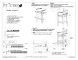
Separate the EXTENSION SLIDES (BB) from the EXTENSION RAILS (AA) as shown in the enlared diaram below. Be
prepared, the parts are reasy.
å
Fasten the EXTENSION RAILS (AA) to the RIGHT END (A) and UPRIGHT (C). Use six BLACK 1/2" PAN HEAD
SCREWS (16).
å
NOTE: For each EXTENSION RAIL, turn a SCREW into the hole shown in the enlared diaram. Then, slide the inner
cartride of the EXTENSION RAIL out to fi nd the other two holes that line up with the holes in the END. Turn a SCREW
into those holes.
å
NOTE: The EXTENSION SLIDES will be used later for the DRAWERS.
Pull up or down on the black lever and pull the SLIDE from the RAIL.
AA
BB
BLACK 1/2" PAN HEAD SCREW
(6 used in this step)
16
Open end
Open end
Rounded corner
Rounded corner
AA
AA
Pae 8 www.sauder.com 420284

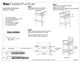
Step 5
C
Roller end
Roller end
Rounded corner
Rounded corner
BLACK 1/2" FLAT HEAD SCREW
(6 used in this step)
17
B
å
Flip the UPRIGHT (C) over.
å
Fasten the CABINET RAILS (CC and DD) to the UPRIGHT (C) and
LEFT END (B). Use six BLACK 1/2" FLAT HEAD SCREWS (17).
CC
DD
Pae 9www.sauder.com420284

å
Fasten the TOP BRACE (H) to the TOP (D). Use four
BLACK 1-1/16" WAFER HEAD SCREWS (19).
Step 6
BLACK 1-1/16" WAFER HEAD SCREW
(4 used in this step)
D
H
Surface with
HIDDEN CAMS
Pae 10 www.sauder.com 420284
19

å
Fasten the LEFT END (B) to the TOP (D). Tihten two
LARGE HIDDEN CAMS.
å
NOTE: Be sure the WOOD DOWELS in the END insert
into the holes in the ede of the TOP.
å
Turn two BLACK 9/16" WAFER HEAD SCREWS (14)
throuh the TOP BRACE (H) and into the LEFT END (B).
Step 7
D
B
BLACK 9/16" WAFER HEAD SCREW
(2 used for the TOP BRACE)
14
H
1
2
Surface with
HIDDEN CAMS
Pae 11

Step 8
1
2
å
Fasten the LARGE BOTTOM (F) to the LEFT END (B).
Tihten two LARGE HIDDEN CAMS.
å
NOTE: Be sure the WOOD DOWELS in the LEFT END
insert into the holes in the LARGE BOTTOM.
Surface with
HIDDEN CAMS
F
Pae 12
B

å
Fasten the UPRIGHT (C) to the TOP (D) and LARGE
BOTTOM (F). Tihten four LARGE HIDDEN CAMS.
å
NOTE: Be sure the WOOD DOWELS in the UPRIGHT
insert into the holes in the LARGE BOTTOM.
å
NOTE: Be sure the WOOD DOWELS in the TOP insert
into the holes in the UPRIGHT.
Step 9
1
2
Surface with
HIDDEN CAMS
C
D
F
Pae 13

å
Fasten the SMALL BOTTOM (G) to the UPRIGHT (C).
Tihten two LARGE HIDDEN CAMS.
å
NOTE: Be sure the WOOD DOWELS in the UPRIGHT
insert into the holes in the SMALL BOTTOM.
Step 10
C
G
Surface with
HIDDEN CAMS
1
2
Pae 14

å
Fasten the RIGHT END (A) to the TOP (D) and SMALL
BOTTOM (G). Tihten four LARGE HIDDEN CAMS.
å
NOTE: Be sure the WOOD DOWELS in the END insert into
the holes in the ede of the TOP and SMALL BOTTOM
å
Turn two BLACK 9/16" WAFER HEAD SCREWS (14)
throuh the TOP BRACE (H) and into the RIGHT END (A).
Step 11
G
A
1
2
BLACK 9/16" WAFER HEAD SCREW
(2 used for the TOP BRACE)
14
Surface without holes
D
Pae 15
H

å
Turn your unit onto the TOP.
å
Fasten the BACK (E) to the ENDS (A and B), UPRIGHT (C),
and BOTTOMS (F and G). Tihten thirteen LARGE HIDDEN
CAMS with the ASSEMBLY TOOL (18).
å
NOTE: Be sure the WOOD DOWELS in the BACK insert
into the holes in the ENDS, UPRIGHTS, and BOTTOMS.
Step 12
A
B
C
F
G
D
Just breathe.
It's oin to be ok.
1
2
Pae 16
E
18

Step 13
Pae 17
BLACK 1/2" MACHINE SCREW
(4 used in the step)
15
å
Fasten the STRETCHER (J) to the LEGS (I and K). Use four
BLACK 1/2" MACHINE SCREWS (15).
å
NOTE: The STRETCHER will fi t over the brackets on the
LEGS.
I
K
J

Step 14
Pae 18
å
Fasten the LEFT LEG (I) to the BACK (E). Use two BLACK 2"
MACHINE SCREWS (10).
å
NOTE: Do not completely tihten the SCREWS at this time.
BLACK 2" MACHINE SCREW
(2 used in this step)
10
I
E

å
Fasten the LEFT and RIGHT LEGS (I and K) to the
BOTTOMS (F and G). Use twelve BLACK 9/16" WAFER
HEAD SCREWS (14).
å
Now, tihten the SCREWS into the BACK (E) completely
at this time.
Step 15
BLACK 9/16" WAFER HEAD SCREW
(12 used for the LEGS)
14
Pae 19
I
K
F
G
E
Tihten these
SCREWS completely.

Step 16
å
Turn ten STRAIGHT HEAD CAM SCREWS (4) into the
DRAWER FRONTS (Q and V).
å
Push twelve SMALL HIDDEN CAMS (2) into the lare
holes in the DRAWER SIDES (L, N, R, and T) and PENCIL
DRAWER BRACE (P).
Straiht head
4
2
Arrow
(10 used)
(10 used)
Arrow
The arrow in the HIDDEN
CAM must point toward the
hole in the ede of the board.
Hole
L
N
R
T
P
V
Q
Pae 20
Page is loading ...
Page is loading ...
Page is loading ...
Page is loading ...
Page is loading ...
Page is loading ...
Page is loading ...
Page is loading ...
-
 1
1
-
 2
2
-
 3
3
-
 4
4
-
 5
5
-
 6
6
-
 7
7
-
 8
8
-
 9
9
-
 10
10
-
 11
11
-
 12
12
-
 13
13
-
 14
14
-
 15
15
-
 16
16
-
 17
17
-
 18
18
-
 19
19
-
 20
20
-
 21
21
-
 22
22
-
 23
23
-
 24
24
-
 25
25
-
 26
26
-
 27
27
-
 28
28


Teknik Hampstead Park Compact Desk 5420284 Instruction Booklet
- Type
- Instruction Booklet
- This manual is also suitable for
Ask a question and I''ll find the answer in the document
Finding information in a document is now easier with AI
Related papers


Other documents
-
POLYWOOD NCRT44GY Operating instructions
-
-
Sauder Costa 421934 User manual
-
 Ivy Terrace IVS110-1-BL Installation guide
-
-
 Bush Furniture BDB145WH-03 Installation guide
-
-
-
-
 Trex Outdoor Furniture TXS120-1-VL Installation guide


