Page is loading ...

InstallatIon GUIDE
725 24 VDC Zone Expansion Module
Description
The 725 24 VDC Zone Expansion Module allows you to increase the number of zones available on DMP panels by
providing four 24 VDC Class B Style A powered zones for the connection of 2-wire smoke detectors. Each zone is
supervised by a 6.8k Ohm End-of-Line resistor. The 725 interfaces to the panel using the 710F Bus Splitter/Repeater,
which allows the connection of a 24 VDC power source to power the smoke detectors and isolates the 24 Volt source
from the panel. Refer to the 710/710F Installation (LT-0310).
The 725 Zone Expansion Module can be installed on individual wire runs up to 2,500 feet, regardless of the gauge of
wire. Up to twenty-ve 725 modules can be installed on the XR100/XR500 Series or XR2500F LX-Bus, and up to eight
725 Zone Expansion Modules can be installed on the Keypad bus. Refer to the panel Installation Guide for additional
information on connecting modules to the panel.
Installing the 725
The 725 easily installs into DMP enclosures using the standard 3-hole conguration. Follow the steps below to
properly mount the 725 in the enclosure:
1. Mount the three plastic standoffs to the enclosure using the three included Phillips head screws.
2. Insert the screws from the outside of the enclosure through the holes and into the plastic standoff which
mounts on the inside of the enclosure and tighten.
3. After securing the standoffs onto the enclosure, snap the 725 onto the standoffs.
If installing on an XR2500F, a 716 Output Expander is needed. If installing on an XR100/XR500 Series, install a Model
305 relay into K6. XR100/XR500 Series panels use a Model 431 6-wire Output Harness on J2. Use Output 1 on the
panel for the sensor reset function or use a 716 Output Expander. See Programming the Panel with a Model 305
Relay Installed.
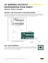
Addressing the 725
The 725 Zone Expansion Module has two rotary switches, labeled S1 (ONES) and S2
(TENS), that allow you to set the module address. To set the module address, use a
small slotted screwdriver and turn the center arrow on each switch to the number
that matches the correct address. See Figure 1.
Keypad Bus Installation
When connecting to the keypad data bus, only the switch labeled S1 (ONES) is used
for addressing. S2 (TENS) must be set to 0 (zero). For XR100/XR500 Series and
XR2500F panels the S2 (TENS) switch can be set to 0 or 1. S1 (ONES) must be set to a
starting address that communicates the four expansion module zone status.
Because the 725 is a four Zone Expansion Module, addressing the 725 to 02, as shown in Figure 1, would make the
zone numbers 21, 22, 23, 24 on any panel. Setting the 725 address to 16 would enable zone numbers 161 to 164
when the 725 is connected to an XR500 Series or XR2500F keypad bus.
LX-Bus Installation
When connecting to an LX-Bus as shown in Figure 2, the two switches are set to match the last two digits of the
starting zone number. For example, setting the module to address 502 (TENS = 0, ONES = 2) makes the module zone
numbers 502, 503, 504, and 505 on an XR500 Series or XR2500F panel.
When using the 716 Output Expander Module to perform a sensor reset, address the 716 following the guidelines in
the 716 Installation Guide (LT-0183).
Zone numbers are determined by the device address. For example, if a 725 on an LX-Bus is addressed to 520, the
four zones are always zone numbers 520, 521, 522, and 523.
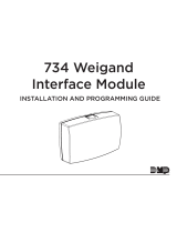
Wiring the 725
The 725 interfaces to the panel using the 710F Bus Splitter Repeater. The XR2500F also requires the use of a 716
Output Expander Module to perform the sensor reset. Refer to the wiring diagrams on the following pages for
illustrations on how to properly wire the 725 Zone Expansion Module.
Note: Use the four included listed 6.8k Ohm EOL resistors when specied.
0
1
2
3
4
5
6
7
8
9
TENS
S2
0
1
2
3
4
5
6
7
8
9
ONES
S1
Example: Rotary
switches set to
address 102 on the
LX-Bus or 2 on the
keypad Bus
Figure 1: Setting the Address

Digital Monitoring Products 725 Installation Guide
2
Programming the XR2500F
After addressing both the 725 Zone Expansion Module and the 716 Output Expander, program the 725 and the 716 in
XR2500F programming accordingly. In panel Programming, scroll to SNSR RST: 0 in OUTPUT OPTIONS. Press any top
row Select key to clear 0. Enter the corresponding 716 output number reset the 725 after a device latches.
If you install the 725 on the keypad bus, scroll to DEVICE SETUP and assign the 725 a device number and select
STD. If you install the 725 on the LX-Bus, no additional programming is necessary. Also program the zones in ZONE
INFORMATION.
S1
S2
ONES
TENS
3 Grn
4 Blk
6 Z1-
7 Z2+
10 Z3-
J16
22
J6
Green
Green
S1 S2
ONES TENS
S
S
S
S
S
S
XR2500F
Fire Alarm Control Panel
Zone Expansion Card:
481, 463G, 462N, 462P, 472
Command
Processor
Reset
Alarm
Circuit
Alarm
Circuit Alarm
Circuit
Alarm
Circuit
6.8k Ohm
EOL Resistor
6.8k Ohm
EOL Resistor
6.8k Ohm
EOL Resistor
6.8k Ohm
EOL Resistor
1 Red
2 Yel
5 Z1+
8 Z2-
9 Z3+
11 Z4+
12 Z4-
Red
Yellow
Black
Green
Yellow
Black
S
S
24 VDC Power Supply
Regulated, Power Limited, and
Listed for Fire Protective Signaling
S
BLK GRN YEL RED
Do NOT connect the RED
terminals to the
24 VDC Power Supply
710F Bus
Splitter / Repeater
BLK GRN YEL RED BLK GRN YEL RED BLK GRN YEL RED
Power Limited
All circuits comply with the requirements for
inherent power limitation and are Class 2.
AC TRBL BATT TRBL
NC C NO NC C NO
725 Zone
Expander
= Supervised Circuit
DC
Red
LED
Green
LED
AC
To 24 VDC
battery
+ BAT -
+ DC DC -
Red
716 Output
Expander
S
SSS
S
S
S
S
Red
Black
Gray (C)
Violet (N/C)
S
S
23 24 25 26 27 28212019181716151413121110987654321
Smoke Detector
Black
Yellow
Red
AC AC BELL+B -B GND REDYEL GRNBLK SMKGND Z1 GND Z2 Z3 GND Z4 Z5 GND Z6 Z7 GND Z8 Z9+Z9- Z10+ Z10-
Black
Note: The LX-Bus and Keypad
Bus circuits are Class B Style 3.5.
Maximum line impedance is 100 Ohms
Z+ Ground fault detected at 650 Ohms or less
Z- Ground fault detected at 390 Ohms or less
Figure 2: Wiring the 725 Zone Expander to the XR2500F Fire Command Center

725 Installation Guide Digital Monitoring Products
3
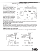
Programming the Panel with a Model 305 Relay Installed
If needed, refer to Figure 4 and Model 305 Relay Installation on the next page. After addressing the 725 and
installing a Model 305 relay into K6 on the panel, program Output 1 for Sensor Reset. In Programming, scroll to
OUTPUT OPTIONS. Then scroll to SNSR RST OUT: 0. Press any top row Select key to clear 0. Press 1 to program
Output 1 to reset the 725 after a device has latched. Program the zones in ZONE INFORMATION.
If the 725 is installed on the keypad bus, scroll to DEVICE SETUP and assign the 725 a device number and select STD.
When installing the 725 on the LX-Bus, no additional programming is necessary.
BLK GRN YEL RED
710F Bus
Splitter / Repeater
BLK GRN YEL RED BLK GRN YEL RED BLK GRN YEL RED
S1
S2
ONES
TENS
3 Grn
4 Blk
6 Z1-
7 Z2+
10 Z3-
1 Red
2 Yel
5 Z1+
8 Z2-
9 Z3+
11 Z4+
12 Z4-
725 Zone
Expander
J4
Command
Processor
Reset
AC
6
AC +B -B BELL GND SMK
GND
REDYELGRN BLKZ1 Z2
GND GND GND GNDZ3 Z4 Z5 Z6 Z7 Z8
Z9+Z9- Z10+ Z10-
J3
J6
J10
K7
To 24 VDC
Battery
AC DC
Green
LED
Red
LED
+ DC DC -
+ BAT -NC C NO NC C NO
Alarm
Circuit
6.8k Ohm EOL
Resistor
Red
Green
Red
Green
Green
S
S
S
S
AC AC
AC TRBL BATT TRBL
Black
Yellow
Red
1
4
32
5
78910 11 12 13 14 15 16 17 18 19 20 21 22 23 24 25 26 27 28
J16
Command Processor™ Panel
6.8k Ohm EOL
Resistor
Alarm
Circuit
Alarm
Circuit
Alarm
Circuit
Yellow
Green
Black
S
S
S
S
S
Power Limited
All circuits comply with the requirements
for inherent power limitation and are Class 2.
Maximum line impedance is 100 Ohms
Z+ Ground fault detected at 650 Ohms or less
Z- Ground fault detected at 390 Ohms or less
725 Zone Expander
= Supervised Circuit
S
Yellow
Black
Black
Yellow
Red
S
S
S
S
S
S
S
S
S
Do NOT connect the RED
terminals to the 24 VDC
Power Supply
Black
Out1 Out2
J2
XR100/XR500 Series
Violet
Gray
K6
Note: The LX-Bus and Keypad
Bus circuits are Class B Style 3.5.
Output 1 Wiring
24 VDC Power Supply
Regulated, Power Limited, and
Listed for Fire Protective Signaling
Figure 3: Wiring the 725 Zone Expander to the XR100/XR500 Series Command Processor Panel

LT-0266 1.01 © 2008 Digital Monitoring Products, Inc.
800-641-4282
www.dmp.com
Made in the USA
INTRUSION • FIRE • ACCESS • NETWORKS
2500 North Partnership Boulevard
Springfield, Missouri 65803-8877
8441
Model 305 Relay Installation
Install the enclosed Model 305 Relay into the K6 relay socket of the panel as
shown in Figure 4. Use the Model 305 relay when using Output 1 located on
Output Header J2.
Be sure that the relay orientation is correct. Notice the small notch at the
bottom of the relay socket. The side of the relay with the two pins should be on
the same side as the notch.
Wiring Specications for Keypad or LX-Bus
Refer to the following LX-Bus and Keypad bus wiring specications.
1. DMP recommends using 18 or 22-gauge unshielded wire for all keypad and LX-Bus circuits. Do not use twisted
pair or shielded wire for LX-Bus and keypad bus data circuits. All 22-gauge wire must be connected to a
power-limited circuit and jacket wrapped.
2. On keypad bus circuits, to maintain auxiliary power integrity when using 22-gauge wire do not exceed 500
feet. When using 18-gauge wire do not exceed 1,000 feet. To increase the wire length or to add devices,
install an additional power supply that is UL listed for Fire Protective Signaling, power limited, and regulated
(12 VDC nominal) with battery backup.
Note: Each panel allows a specic number of supervised keypads. Add additional keypads in the unsupervised
mode. Refer to the panel installation guide for the specic number of supervised keypads allowed.
3. Maximum distance for any one bus circuit (length of wire) is 2,500 feet regardless of the wire gauge. This
distance can be in the form of one long wire run or multiple branches with all wiring totaling no more than
2,500 feet. As wire distance from the panel increases, DC voltage on the wire decreases. Maximum number
of LX-Bus devices per 2,500 feet circuit is 40.
4. Maximum voltage drop between the panel (or auxiliary power supply) and any device is 2.0 VDC. If the
voltage at any device is less than the required level, add an auxiliary power supply at the end of the circuit.
When voltage is too low, the devices cannot operate properly.
For additional information refer to the panel’s Installation Guide, the LX-Bus/Keypad Bus Wiring Application Note
(LT-2031), and/or the 710/710F Installation Sheet (LT-0310).
Compliance Listing Specications
UL Commercial Fire
The 725 Zone Expansion Module operates on 24 VDC power supplied by a 24 VDC Power Supply listed for Fire
Protective Signaling.
Heat detectors, 4-wire smoke detectors, manual pull stations and other re initiating devices that do not require
compatibility listing by UL can be connected to the 725 Zone Expansion Module in most applications.
All re device installations must be in accordance with the manufacturer’s instructions, NFPA standards, and the
requirements of the Authority Having Jurisdiction (AHJ).
See the panel installation guide for details for selecting compatible 2-wire smoke detectors.
The smoke detector compatibility identier is B.
Specications
Current Draw
Operating 8mA
+ 4mA per active zone
Maximum 8mA
+ 4mA per active zone
+ 30mA per smoke in alarm
+ 48mA per shorted device
Operating Voltage 24 VDC
EOL Resistor 6.8k Ohm EOL resistor
Panel Compatibility
XR100/XR500 Series and XR2500F Command Processor™ Panels
Accessories
710F Fire Bus Splitter/Repeater Module
2-wire smoke detectors (24 VDC)
Listings and Approvals
California State Fire Marshal (CSFM)
New York City (FDNY COA #6055)
Underwriters Laboratories (UL) Listed
ANSI/UL 864 Fire Protective Signaling
K6
Observe the
orientation
notch on the
relay socket.
Figure 4: Relay Installation
/