
SG10_12KTL-M-UEN-Ver10-201705 Version: 1.0
User Manual
SG10KTL-M/SG12
KTL-M
PV Grid-connected
Inverter


I
About This Manual
This manual is for the SG10KTL-M/SG12KTL-M, a 3-phase PV grid-connected inverter
without a transformer, (hereinafter referred to as inverter unless otherwise specified).
The inverter is grid-connected, transformer-less, robust and of high conversion
efficiency.
Aim
This manual contains information about the inverter, which will provide guidelines
on connecting the inverter into the PV power system and how to operate the
inverter.
Related Documents
The manual cannot include all information about the PV system. You may get
additional information at www.sungrowpower.com.
Target Group
This manual is for technical personnel who are responsible for inverter installation,
operation and maintenance, and the inverter owner who will perform daily APP
operation.
How to Use This Manual
Read the manual and other related documents before commencing any work on the
inverter. Documents must be stored carefully and available at all times.
All rights reserved including the pictures, markings and symbols used. Any
reproduction or disclosure, even partially, of the contents of this manual is strictly
forbidden without prior written authorization of Sungrow.
The contents of the manual will be periodically updated or revised due to product
development. There may be changes in the manual due to subsequent inverter
editions. The latest manual can be acquired via visiting the web site at
www.sungrowpower.com.
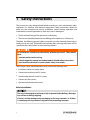
Symbols Explanation
Important instructions contained in this manual should be followed during
installation, operation and maintenance of the inverter. And they will be highlighted

II
by the following symbols.
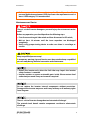
DANGER indicates a hazard with a high level of risk which, if not avoided,
will result in death or serious injury.
WARNING indicates a hazard with a me
dium level of risk which, if not
avoided, could result in death or serious injury.
CAUTION indicates a hazard with a low level of risk which, if not avoided,
could result in minor or moderate injury.
NOTICE indicates a situation
which, if not avoided, could result in
equipment or property damage.
NOTE indicates additional information, emphasized contents or tips to
help you solve problems or save time.
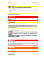
Symbols on the Inverter Body
WARNING
Disconnect the inverter from all the
external power sources before service!
Do not touch live parts until
10 minutes after disconnection
from the sources!
10 min
Hot surface! May exceed 60
℃!
Danger to life due to high voltages!
Only qualified personnel can open
and service the product!
Check user manual before service!

III
Contents
About This Manual .......................................................................... I
1 Safety Instructions ................................................................... 1
2 Product Description ................................................................. 6
2.1 Intended Usage ...................................................................................................... 6
2.2 Product Introduction ............................................................................................ 7
Appearance ................................................................................................................. 7 2.2.1
Dimensions .................................................................................................................. 8 2.2.2
LED Indicator Panel .................................................................................................. 8 2.2.3
DC Switch .................................................................................................................. 10 2.2.4
2.3 Technical Description ........................................................................................ 10
Circuit Diagram ....................................................................................................... 10 2.3.1
Function Description ............................................................................................ 11 2.3.2
Derating ..................................................................................................................... 12 2.3.3
3 Installation Flow..................................................................... 16
4 Unpacking and Storage ......................................................... 18
4.1 Unpacking and Inspection .............................................................................. 18
4.2 Identifying Inverter ............................................................................................ 18
4.3 Scope of Delivery ................................................................................................ 20
4.4 Inverter Storage ................................................................................................... 20
5 Mechanical Installation ......................................................... 22
5.1 Installation Site Selection ................................................................................ 22
5.2 Moving Inverter to Installation Site .............................................................. 24
5.3 Installation Tools.................................................................................................. 25
5.4 Installing the Inverter ........................................................................................ 25
Installing to Metal Frame .................................................................................... 26 5.4.1
Installing to Concrete Wall .................................................................................. 27 5.4.2
6 Electrical Connection ............................................................. 29

IV
6.1 Terminal Description ......................................................................................... 29
6.2 AC Side Cable Connection ............................................................................... 30
AC side requirements ........................................................................................... 30 6.2.1
Grid Connection ..................................................................................................... 31 6.2.2
6.3 Connecting Inverter to PV Arrays .................................................................. 33
PV Input Configuration ........................................................................................ 34 6.3.1
PV Input Connection ............................................................................................. 35 6.3.2
6.4 Grounding the Inverter ..................................................................................... 38
Grounding System Overview............................................................................. 38 6.4.1
Second Protective Earth Terminal .................................................................... 39 6.4.2
6.5 RS485 Communication Connection ............................................................. 40
Communication Overview.................................................................................. 40 6.5.1
RS485 Communication System ......................................................................... 41 6.5.2
PLC Communication Connection ..................................................................... 42 6.5.3
7 Commissioning ...................................................................... 44
7.1 Inspection before Commissioning ............................................................... 44
7.2 Commissioning Procedure .............................................................................. 44
8 Disconnecting, Dismantling and Disposing the Inverter .... 47
8.1 Disconnecting the Inverter ............................................................................. 47
8.2 Dismantling the Inverter .................................................................................. 47
8.3 Disposal of the Inverter .................................................................................... 48
9 Troubleshooting and Maintenance ...................................... 49
9.1 Troubleshooting .................................................................................................. 49
9.2 Maintenance ......................................................................................................... 53
9.3 Contact Sungrow Service ................................................................................. 53
10 Sun Access APP................................................................... 54
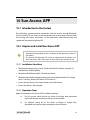
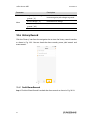
10.1 Introduction to the System ............................................................................. 54
10.2 Acquire and install Sun Access APP.............................................................. 54
Installation Condition ........................................................................................ 54 10.2.1
Operation Steps ................................................................................................... 54 10.2.2
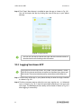
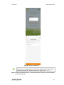
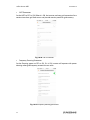
10.3 Logging Sun Access APP .................................................................................. 55

V
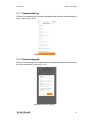
10.4 Homepage ............................................................................................................. 58
10.5 Run Info .................................................................................................................. 59
10.6 History Record ...................................................................................................... 61
Fault Alarm Records ............................................................................................ 61 10.6.1
Power Yields Records .......................................................................................... 63 10.6.2
Event Records ........................................................................................................ 65 10.6.3
10.7 More ......................................................................................................................... 66
Power On/Power Off ........................................................................................... 66 10.7.1
System Parameters .............................................................................................. 67 10.7.2
Operation Parameters ........................................................................................ 68 10.7.3
Protection Parameters ....................................................................................... 74 10.7.4
Communication Parameters ............................................................................ 76 10.7.5
Advanced Settings .............................................................................................. 77 10.7.6
Download the Log ............................................................................................... 78 10.7.7
Firmware Upgrade ............................................................................................... 78 10.7.8
About Sun Access ................................................................................................ 79 10.7.9
11 Appendix ................................................................................ 80
11.1 Technical Data ...................................................................................................... 80
11.2 Exclusion of Liability .......................................................................................... 81
11.3 About Us ................................................................................................................ 82
11.4 Contact Information .......................................................................................... 82

1
1 Safety Instructions
The inverter has been designed and tested according to strict international safety
regulations. As electrical and electronic equipment, safety instructions related to
them must be complied with during installation, commissioning, operation and
maintenance. Incorrect operation or work may result in damage to:
The life and well-being of the operator or a third party
The inverter and other properties that belong to the operator or a third party
Therefore, the following general safety instructions must be read and always kept in
mind prior to any work. All detailed work-related safety warnings and notes will be
specified at the critical points in corresponding chapters.
All installations should be performed by technical personnel. They should
have:
received professional training;
read through this manual and understood all related safety instructions;
been familiar with electric system related safety instructions.
Technical personnel mentioned above may perform the following work:
Install the inverter in a proper place;
Connect the inverter to the PV system;
Connect other devices to the PV system;
Commission the inverter;
Operate and maintain the inverter.
Before Installation
The unit is thoroughly tested and strictly inspected before delivery. Damage
may still occur during shipping.
If there is visible damage to the packaging or the inner contents, or if there
is something missing, contact Sungrow or the forwarding company.

User Manual 1 Safety Instructions
2
There is a risk of injury due to improperly handling the device!
Always follow the instructions in the manual when moving and
positioning the inverter.
Injuries, serious wounds, or bruises may occur if the device is improperly
handled.
During Mechanical Installation
Make sure inverter is n
ot electrically connected before installing the
inverter.
System performance loss due to bad ventilation!
Proper-
ventilation should be maintained during device operation. the fan’s
air inlet and outlet should not be covered to ensure the device interior can
sufficiently cool down.
During Electrical Connection
All electrical connections
must be in accordance with national and local
standards.
The connection to the grid can be done only after receiving approval from
the local utility grid company.
Lethal voltage exists!
PV arrays will produce electrical energy when exposed to sunlight and thus can
create potential electrical shock hazards.
All cables must be firmly attached, undamaged, properly insulated and
adequately dimensioned.

1 Safety Instructions User Manual
3
During Inverter Operation
Do not open inverter enclosure when inverter is under load or operating.
Only an intact and locked inverter cabinet can ensure personal and
property safety.
There is a risk of burn!
Do not touch hot compoenets of the inverter (for example, the heatsink)
during operation. Only the DC switch can be touched during operation.
Operate the inverter by strictly following the descriptions in this manual to avoid
unnecessary injury to persons and damage to the device. Arc flash, fire or explosion
may occur if done otherwise and Sungrow will hold no liability for damages.
The following improper operations can cause an arc flash, fire and explosion
inside the device. Keep in mind that these accidents can only be handled by
qualified personnel. Improper handling of these accidents may lead to a
more serious fault or accident.
Pluging in and unpluging the DC side HV fuse when it is alive;
Touching the end of the cables that has no insulation and may still be
alive;
Touching
the connection copper bus bar, terminal or other spare parts
inside the device that may be alive;
The power cable connection is loose;
Spare parts, such as bolts, are falling inside the inverter;
Incorrect operation by unqualified persons that have not received
training;
Before any operation of the device, a preliminary arc flash assessment in the
operation area is necessary. If there is a possibility of an arc flash,
The operators must receive related safety training;
Use best practices to assess the areas that may be affected by an arc
flash ;

User Manual 1 Safety Instructions
4
Before any operation in the area that may be affected by and arc flash,
personal protective equipment (PPE) that meets the requirement must be
worn. A PPE category 2 is recommended.
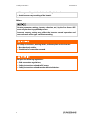
Maintenance and Service
There is a risk of inverter damage or personal injury due to incorrect service
work!
Before any operation, you should perform the following steps:
First disconnect the grid side switch and then disconnect he DC switch;
Wait at least 10 minutes until the inner capacitors are discharged
completely;
V
erify, using proper testing device to make sure there is no voltage or
current.
Keep unqualified persons away!
A temporary warning sign and barrier must be posted to keep unqualified
persons away during electrical connection and maintenance.
Restart the inverter only when the fault that may impair the inverter
safety functions is removed.
Inverter contains no owner serviceable parts inside. Please contact local
authorized personnel if any service work is required.
D
o not replace the inverter internal components without permission.
Damage to the inverter may occur and it may void any or all warranty rights
from Sungrow.
There is a risk of inverter damage due to electrostatic discharge!
T
he printed circuit boards contain components sensitive to electrostatic
discharge.

1 Safety Instructions User Manual
5
Wear a grounding wrist band when handling the boards.
Avoid unnecessary touching of the boards.
Others
Certain parameter settings (country selection, etc.) by the Sun Access APP
must only be done by qualified persons.
I
ncorrect country setting may affect the inverter normal operation and
cause a breach of the type-certificate marking.
All safety instructions, warning labels, and nameplate on the inverter:
Must be clearly visible;
Should not be removed or covered.
Respect the following regulations:
Grid-connection regulations;
Safety instructions related to PV arrays;
Safety instructions related to other electrical devices.

6
2 Product Description
2.1 Intended Usage
SG10KTL-M/SG12KTL-M; a transformerless 3-phase PV grid-connected inverter , is an
integral component in the PV power system.
The inverter is designed to convert the direct current power generated from the PV
modules into grid-compatible AC current and feeds the AC current to the utility grid.
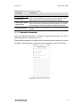
The intended usage of the inverter is illustrated in Fig. 2-1.
Inverter cannot connect the PV strings whose positive and negative
terminals need to be grounded.
D
o not connect any local load between the inverter and the AC circuit
breaker.
Inverter is applicable only to the grid-connected PV system. Any other
usage is strictly forbidden.
A B C D
Fig. 2-1 Inverter application in PV power system
Item
Description
Note
A PV strings Monocrystalline silicon; polycrystalline silicon and
thin-film without grounding
B
Inverter
SG10KTL-M/SG12KTL-M
C
Metering
device
meter cupboard with power distribution system
D Utility grid TN-C,TN-C-S,IT
The following figure shows the common grid configurations.

2 Product Description User Manual
7
L2
L1
L3
PE
IT
Transformer
L2
PEN
L1
L3
PE
TN-C
Transformer Transformer
L2
N
PE
L1
L3
PE
TN-C-S
SG10KTL-M/
SG12KTL-M SG10KTL-M/
SG12KTL-M SG10KTL-M/
SG12KTL-M
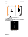
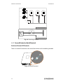
2.2 Product Introduction
Appearance 2.2.1
2
1
3
4
5
2
Fig. 2-2 Appearance
* Pictures are indicative only. Product in kind prevail.
No.
Name
Description
1 LED indicator panel
HMI interface to indicate the present working state
of the inverter.
2 DC switch
Protective components to safely disconnect DC side
current.
3
Electrical connection
area
Includes DC terminal, AC terminal and RS485
communication terminal.
4
PE second terminal
User can connect this terminal as per requirements.
5
Hanger
Hang the inverter on the backplate.

User Manual 2 Product Description
8
Dimensions 2.2.2
160
485
370
Fig. 2-3 Dimensions of the inverter (in mm)
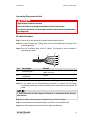
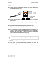
LED Indicator Panel 2.2.3
As a HMI interface, the LED indicator panel on the inverter front panel indicates the
present working state of the inverter.
Fig. 2-4 LED indicator panel

2 Product Description User Manual
9
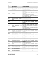
Tab. 2-1 State description of the LED indicator panel
LED indicator
LED color
LED state
Definition
Bluetooth Blue
ON
The Bluetooth
communication is
connected and there is not
data communication
OFF
No device connected to the
inverter through the
Bluetooth.
Periodical flash
The Bluetooth
communication is
connected and there is data
communication
Communication Blue
OFF
The RS485 communication
cable is not connected or
the communication channel
has no data interaction
Periodical flash
The RS485 communication
cable is connected and the
communication channel has
data interaction
Fault/alarm
Red
Off No fault has occurred
ON A fault occurs, not including
the communication falult.
Yellow
Off No alarm has occurred
ON
An alarm occures. The alarm
type can be: communication
fault (between the ARM and
the DSP or PLC), fan fault, AC
side SPD alarm, DC side SPD
alarm, insufficient sunlight,
PV overload, PV anomaly
alarm, AFD module anomaly
alarm and AFD off alarm.

User Manual 2 Product Description
10
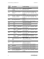
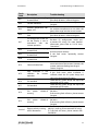
LED indicator
LED color
LED state
Definition
Earth
impedance
abnormal
Red
OFF
No fault occured
ON
An earth impedance
short-circuit fault occured
(the device cannot connect
to the grid)
Normal
operation Green
OFF
Both the AC and DC is
powered down
Periodical flash
The DC or AC is powered on
and the device is in standby
or startup state (not connect
to the grid)
ON
The device is connected to
the grid and operating
normally
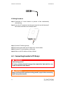
DC Switch 2.2.4
The DC switch is used to disconnect the DC current safely whenever necessary.
The inverter operates automatically when input and output requirements are met.
Turn the DC switch to the OFF position to stop the inverter when a fault occurs or
when you need to stop the inverter.
Turn the DC switch to the ON position before restarting the inverter.
2.3 Technical Description
Circuit Diagram 2.3.1
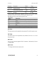
Fig. 2-5 shows the main circuit of the inverter.
The MPPT is utilized for DC input to ensure the maximum power from the PV array at
different PV input conditions.
The inversion circuit converts the DC power into AC power and feeds the AC power
to the utility grid through the AC terminal. The protection circuit is equipped to
ensure the safe operation of the device and personal safety.
The DC switch is used to disconnect the DC current safely. The inverter provides
standard RS485 ports for communication. Users can check running data and set
related parameters through the Sun Access APP.

2 Product Description User Manual
11
AC
EMI
Filter
AC
Filter
MPPT1
(Boost 1)
Inverter Circuit
(DC/AC)
MPPT2
(Boost 2)
DC1
DC EMI
Filter
DC2
DC Switch
L1
L2
L3
PE
DC SPD
DC Bus
N
AC
Relays
AC SPD
Fig. 2-5 Circuit diagram of SG10KTL-M/SG12KTL-M
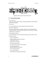
Function Description
2.3.2
Inversion function
The inverter converts the DC current into grid-compatible AC current and feeds
the AC current into grid.
Data storage
The inverter achieves the running information, fault records and etc.
Parameter Configuration
The inverter provides various parameter settings. You can set the parameters
through the phone’s APP to change the requirements of the device or optimize
the performance of the device.
Communication Interface
Standard RS485 port, can be connected to monitoring a device and PV system
Protection Function
− Short-circuit protection
− Ground insulation resistance monitoring
− Grid voltage monitoring
− Grid frequency monitoring
− Residual current protection
− DC injection of AC output current monitoring
− Anti-islanding protection
− Ambient temperature monitoring
− DC over-voltage protection
− Over-current protection
− Power module over-temperature protection

User Manual 2 Product Description
12
Derating
2.3.3
Output derating is a way to protect the inverter form overload or potential faults.
Situations requiring inverter power derating are:
Ambient temperature is too high
Gird voltage is too low
Fluctuations of external power level
Input voltage is too high
Altitude is too high
Power Limit Setting
Inverter output power can be adjusted via the APP interface or remote grid dispatch
from the grid company. The corresponding operating state will display on the LED
Indicator Panel.
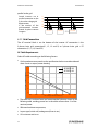
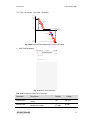
Over-temperature Derating
High ambient temperature, a broken fan or poor ventilation will lead to inverter
power derating.
When the module temperature exceeds the upper limit, the inverter will derate
power output until the temperature drops within the permissible range.
When the inverter internal temperature exceeds the upper limit, the inverter will
derate power output until the temperature drops within the permissible range.
45 60
Output Power
(kVA)
10
Over-temperature derating curve of SG10KTL-M
(Vac=400V)
3.0
Temperature(℃)
Vmmp=470V
30
Vmmp=600V
Vmmp=850V
2.0
0

2 Product Description User Manual
13
45 60
Output Power
(kVA)
12
Over-temperature derating curve of SG12KTL-M
(Vac=400V)
3.6
Temperature(℃)
Vmmp=550V
30
Vmmp=590V
Vmmp=850V
2.4
0
Lower limit of the over-temperature derating: 20% of the nominal power.
When both the module temperature and the internal temperature meet
the derating condition, inverter limits its power according to the lower
power limitation value of the two.
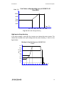
Grid Under-voltage Derating
When the grid voltage is low, the inverter will derate the output power to make sure
the output current is within the permissible range. Once the grid voltage is within
Vmin…600V, the inverter will derate the output power.
300270240210180150120
10000
8000
5000
3000
Pout
(W)
Vac(V)
Grid Under-voltage derating curve of SG10KTL-M
(Vdc=600V)
0
6000
Page is loading ...
Page is loading ...
Page is loading ...
Page is loading ...
Page is loading ...
Page is loading ...
Page is loading ...
Page is loading ...
Page is loading ...
Page is loading ...
Page is loading ...
Page is loading ...
Page is loading ...
Page is loading ...
Page is loading ...
Page is loading ...
Page is loading ...
Page is loading ...
Page is loading ...
Page is loading ...
Page is loading ...
Page is loading ...
Page is loading ...
Page is loading ...
Page is loading ...
Page is loading ...
Page is loading ...
Page is loading ...
Page is loading ...
Page is loading ...
Page is loading ...
Page is loading ...
Page is loading ...
Page is loading ...
Page is loading ...
Page is loading ...
Page is loading ...
Page is loading ...
Page is loading ...
Page is loading ...
Page is loading ...
Page is loading ...
Page is loading ...
Page is loading ...
Page is loading ...
Page is loading ...
Page is loading ...
Page is loading ...
Page is loading ...
Page is loading ...
Page is loading ...
Page is loading ...
Page is loading ...
Page is loading ...
Page is loading ...
Page is loading ...
Page is loading ...
Page is loading ...
Page is loading ...
Page is loading ...
Page is loading ...
Page is loading ...
Page is loading ...
Page is loading ...
Page is loading ...
Page is loading ...
Page is loading ...
Page is loading ...
Page is loading ...
Page is loading ...
-
 1
1
-
 2
2
-
 3
3
-
 4
4
-
 5
5
-
 6
6
-
 7
7
-
 8
8
-
 9
9
-
 10
10
-
 11
11
-
 12
12
-
 13
13
-
 14
14
-
 15
15
-
 16
16
-
 17
17
-
 18
18
-
 19
19
-
 20
20
-
 21
21
-
 22
22
-
 23
23
-
 24
24
-
 25
25
-
 26
26
-
 27
27
-
 28
28
-
 29
29
-
 30
30
-
 31
31
-
 32
32
-
 33
33
-
 34
34
-
 35
35
-
 36
36
-
 37
37
-
 38
38
-
 39
39
-
 40
40
-
 41
41
-
 42
42
-
 43
43
-
 44
44
-
 45
45
-
 46
46
-
 47
47
-
 48
48
-
 49
49
-
 50
50
-
 51
51
-
 52
52
-
 53
53
-
 54
54
-
 55
55
-
 56
56
-
 57
57
-
 58
58
-
 59
59
-
 60
60
-
 61
61
-
 62
62
-
 63
63
-
 64
64
-
 65
65
-
 66
66
-
 67
67
-
 68
68
-
 69
69
-
 70
70
-
 71
71
-
 72
72
-
 73
73
-
 74
74
-
 75
75
-
 76
76
-
 77
77
-
 78
78
-
 79
79
-
 80
80
-
 81
81
-
 82
82
-
 83
83
-
 84
84
-
 85
85
-
 86
86
-
 87
87
-
 88
88
-
 89
89
-
 90
90


Sungrow SG10KTL-M User manual
- Type
- User manual
- This manual is also suitable for
Ask a question and I''ll find the answer in the document
Finding information in a document is now easier with AI
Related papers
Other documents
-
 Renovo Digiwatts RN5000US Installation guide
-
Delta M100_210 User manual
-
CPS SCA25KTL-DO-R User manual
-
-
 Phocos Any-Grid Battery Inverter Charger PSW-B User manual
-
Delta PMC-24V600W1RW User manual
-
 Siliken SE4i User manual
-
APPS Wi-Fi Module and WatchPower Apps User manual
-
BYD Battery-Box L Series Installation Guidance
-


