Page is loading ...

www.ismacontrolli.com
The performances stated in this sheet can be modifi ed without any prior notice.
pag. 1DIM233en | 1st Issue rev. 2 | 07/2022
MVT5xx
Modulating Actuator
YES
NO
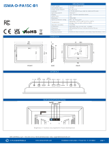
MOUNTING INSTRUCTIONS
Do not use the actuator if not coupled with the valve.
INSTALLATION
Use manual override to set the spindle in the installation position.
Set the actuator spindle in the retract position.
MVTxxxS
Align actuator spindle slot with the hole in locknut (A),
secure with bolt (B) through non threaded hole in lock-
nut (A).
MVTxxx
YES

www.ismacontrolli.com
iSMA CONTROLLI S.p.A. - Via Carlo Levi 52, 16010 Sant’Olcese (GE) - Italy | [email protected]
pag. 2DIM233en | 1st Issue rev. 2 | 07/2022
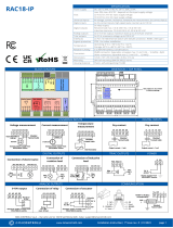
WIRING DIAGRAMS
REPLACEMENT OF THE OLD PROPORTIONAL MVT
Connect together the white and the green cable; then connect the white cable of the new actuator in place of the white cable of
MVT56/57, the new blue cable in place of the old green cable and the new red cable in place of the old brown cable.
If you need you can make use of the feedback signal, not available on the old models of actuator. Do not make electrical connection
or changing operation in case actuators are powered.
DIP SWITCHES SELECTION
DIP OFF (DEFAULT) ON
1 Direct Action Reverse Action
2 Range 0-10V / 0-5V Range 2-10 / 6-10
3 No sequence Sequence
4Auto Stroke Fixed Stroke
5Voltage range 4-20mA range
6Normal running Learning
Fixed stroke actuators DIP selection
DIP 1 DIP 6 FIXED STROKE
[mm]
OFF OFF 5
OFF ON 5,5
ON OFF 2,5
ON ON 3,5
VALID ONLY IF DIP 4 IN ON
LEDs DESCRIPTION
LEDs
CALIBRATION PHASE
INITIAL POSITIONING
UP POSITIONING
END STROKE UP
DOWN POSITIONING
END STROLE DOWN
ACTUATOR STOP
UNEXPECTED STALL
LOW SUPPLY VOLTAGE
ACTUATOR OFF OR UNDER
RESET (SUPPLY VOLTAGE
LOW)
MAX STROKE
LIMIT PHASE
YELLOW ON ON ON ON ON ON ON ON BLINKING
1Hz OFF ON
RED ALTERNA-
TING 5Hz
ALTERNA-
TING 1Hz
OFF OFF BLINKING
1Hz ON OFF SIMULTANE-
OUS 5Hz
OFF OFF ON
GREEN BLINKING
1Hz ON OFF OFF OFF OFF OFF ON
/