iSMACONTROLLI iSMA-B-AAC20-LCD User manual
- Type
- User manual

iSMA CONTROLLI S.p.A. – Via Carlo Levi 52, 16010 Sant’Olcese (GE) - Italy |
support@ismacontrolli.com
www.ismacontrolli.com Installation Instruction| 2nd Issue rev. 6 | 01/2022 page 1
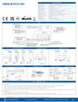
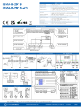
TOP PANEL
UNIVERSAL INPUTS
DIGITAL INPUTS
Voltage measurement
Current measurement
Temperature
measurement
Dry contact input
Dry contact input
DIGITAL OUTPUTS
COMMUNICATION
POWER SUPPLY
Connection of electrovalve
Connection of resistive
load
Connection of inductive
load
ANALOG OUTPUTS
DALI
M-Bus
0-10 V output
Connection of relay
Connection of actuator
iSMA-B-AAC20-LCD
iSMA-B-AAC20-LCD-D
iSMA-B-AAC20-LCD-M
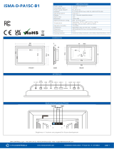
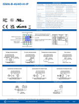
SPECIFICATION
Power supply
DC: 24 V ± 20%, 5 W/*7 W; AC: 24 V ± 20%, 7.5 VA/*10,5 VA
(*with extension)
Universal inputs
8 - voltage, current, resistance and temperature measurement, dry
contact
Digital inputs
4 - dry contact input, high-speed pulse counter up to 100 Hz
Digital outputs
4 - relay output;
Resistive load max. 3 A @ 230 V AC, 3 A @ 30 V DC
Inductive load max. 75 VA @ 230 V AC, 30 W @ 30 V DC
Analog outputs
6 - 0-10 V DC output, maximum load up to 20 mA (A6 up to 5 mA)
Processor
Cortex M4 + M0 (204 MHz), Sedona Virtual Machine 1.2.28
Interface
Standard
2x Ethernet, RS485, Host USB, 1-Wire, RJ12 connector
Extensions
DALI (opto-isolated, power supply for 130 mA max.)
M-Bus (opto-isolated, power supply for 20 devices max.)
Ingress protection
IP40 - for indoor installation
Temperature
Operating: -10°C to +50°C (14°F to 122°F)
Storage -40°C to +85°C (-40°F to +185°F)
Relative humidity
5 to 95% RH (without condensation)
Connectors
Separable max 2.5 mm2 (18 … 12 AWG)
Dimensions
106 x 110 x 62 mm (4.17 x 4.33 x 2.44 in)
Mounting
DIN rail mounting (DIN EN 50022 norm)
Housing material
Plastic, self-extinguishing PC/ABS

iSMA CONTROLLI S.p.A. – Via Carlo Levi 52, 16010 Sant’Olcese (GE) - Italy |
support@ismacontrolli.com
www.ismacontrolli.com Installation Instruction| 2nd Issue rev. 6 | 01/2022 page 2
WARNING
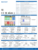
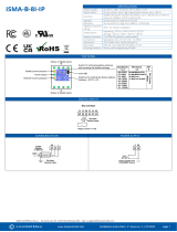
BLOCK DIAGRAM
1-WIRE
• Note, an incorrect wiring of this product can damage it and
lead to other hazards. Make sure the product has been
correctly wired before turning the power ON.
• Before wiring, or removing/mounting the product, be sure
to turn the power OFF. Failure to do so might cause electric
shock.
• Do not touch electrically charged parts such as the power
terminals. Doing so might cause electric shock.
• Do not disassemble the product. Doing so might cause
electric shock or faulty operation.
• Use the product within the operating ranges
recommended in the specification (temperature, humidity,
voltage, shock, mounting direction, atmosphere, etc.).
Failure to do so might cause fire or faulty operation.
• Firmly tighten the wires to the terminal. Insufficient
tightening of the wires to the terminal might cause fire.
RS485 CONFIGURATION
In the iSMA-B-AAC20 device there is a built-in 3 position switch, which is dedicated to connect 120 Ω termination resistor and/or biasing resistors. It
can be accessed by removing the bottom part of enclosure.
Switch Position
Biasing
Termination 120 Ω
1 (END)
ON
ON
2 (BIA) - default
ON
OFF
3 (NONE)
OFF
OFF
FCC COMPLIANCE NOTE
Note: This equipment has been tested and found to comply with the limits for a Class A digital device, pursuant to part 15 of the FCC Rules. These
limits are designed to provide reasonable protection against harmful interference when the equipment is operated in a commercial environment.
This equipment generates, uses, and can radiate radio frequency energy and, if not installed and used in accordance with the instruction manual,
may cause harmful interference to radio communications. Operation of this equipment in a residential area is likely to cause harmful interference in
which case the user will be required to correct the interference at his own expense.
WIRING
• Line power cables must be routed with spatial separation from signal and data transmission cables.
• Analog and digital signal cables should also be separated.
• It is recommended to use shielded cables for analog signals, cable shields should not be interrupted by intermediate terminals.
• The shielding should be earthed directly after the cable enters the cabinet.
• It is recommended to install interference suppressors when switching inductive loads (e.g., coils of contactors, relays, solenoid valves). RC
snubbers or varistors are suitable for AC voltage and freewheeling diodes for DC voltage loads. The suppressing elements must be
connected as close to the coil as possible.
Bottom view of the board

iSMA CONTROLLI S.p.A. – Via Carlo Levi 52, 16010 Sant’Olcese (GE) - Italy |
support@ismacontrolli.com
www.ismacontrolli.com Installation Guideline| 1st Issue rev. 1 | 05/2022
INSTALLATION GUIDELINE
Please read the instruction before use or operating the device. In case of any questions after
reading this document, please contact the iSMA CONTROLLI Support Team
(support@ismacontrolli.com).
• Before wiring or removing/mounting the product, make sure to turn the power off. Failure to do so
might cause an electric shock.
• Improper wiring of the product can damage it and lead to other hazards. Make sure that the product
has been correctly wired before turning the power on.
• Do not touch electrically charged parts such as power terminals. Doing so might cause an electric shock.
• Do not disassemble the product. Doing so might cause an electric shock or faulty operation.
• Use the product only within the operating ranges recommended in the specification (temperature,
humidity, voltage, shock, mounting direction, atmosphere, etc.). Failure to do so might cause a fire or
faulty operation.
• Firmly tighten the wires to the terminal. Failure to do so might cause a fire.
• Avoid installing the product in close proximity to high-power electrical devices and cables, inductive loads, and switching devices.
Proximity of such objects may cause an uncontrolled interference, resulting in an instable operation of the product.
• Proper arrangement of the power and signal cabling affects the operation of the entire control system. Avoid laying the power and
signal wiring in parallel cable trays. It can cause interferences in monitored and control signals.
• It is recommended to power controllers/modules with AC/DC power suppliers. They provide better and more stable insulation for
devices compared to AC/AC transformer systems, which transmit disturbances and transient phenomena like surges and bursts to
devices. They also isolate products from inductive phenomena from other transformers and loads.
• Power supply systems for the product should be protected by external devices limiting overvoltage and effects of lightning
discharges.
• Avoid powering the product and its controlled/monitored devices, especially high power and inductive loads, from a single power
source. Powering devices from a single power source causes a risk of introducing disturbances from the loads to the control devices.
• If an AC/AC transformer is used to supply control devices, it is strongly recommended to use a maximum 100 VA Class 2
transformer to avoid unwanted inductive effects, which are dangerous for devices.
• Long monitoring and control lines may cause loops in connection with the shared power supply, causing disturbances in the
operation of devices, including external communication. It is recommended to use galvanic separators.
• To protect signal and communication lines against external electromagnetic interferences, use properly grounded shielded cables
and ferrite beads.
• Switching the digital output relays of large (exceeding specification) inductive loads can cause interference pulses to the electronics
installed inside the product. Therefore, it is recommended to use external relays/contactors, etc. to switch such loads. The use of
controllers with triac outputs also limits similar overvoltage phenomena.
• Many cases of disturbances and overvoltage in control systems are generated by switched, inductive loads supplied by alternating
mains voltage (AC 120/230 V). If they do not have appropriate built-in noise reduction circuits, it is recommended to use external
circuits such as snubbers, varistors, or protection diodes to limit these effects.
Electrical installation of this product must be done in accordance with national wiring codes and conform to
local regulations.
-
 1
1
-
 2
2
-
 3
3


iSMACONTROLLI iSMA-B-AAC20-LCD User manual
- Type
- User manual
Ask a question and I''ll find the answer in the document
Finding information in a document is now easier with AI
Related papers
-
 iSMACONTROLLI iSMA-B-FCU-HH IBC Intelligent Building Controls User manual
-
iSMACONTROLLI TP User manual
-
iSMACONTROLLI SFAR-S-6TI User manual
-
iSMACONTROLLI SFAR-1M-4DI Operating instructions
-
iSMACONTROLLI iSMA-B-AAC20 User manual
-
-
 iSMACONTROLLI SfAR-1M-2DI2DO Expansion Module 2 Digital Inputs 2 Digital Outputs User manual
-
iSMACONTROLLI SFAR-S-8DI8DO User manual


Other documents
-
 iSMA CONTROLLI iSMA-D-PA15C-B1 User manual
-
iSMA CONTROLLI iSMA-B-MIX38-IP Installation guide
-
 iSMA CONTROLLI iSMA-B-2D Installation guide
-
 iSMA CONTROLLI RAC18-IP Installation guide
-
 iSMA CONTROLLI iSMA-B-4U4A-H-IP Installation guide
-
 iSMA CONTROLLI iSMA-B-2D1B Installation guide
-
 iSMA CONTROLLI iSMA-B-4U4O-H Installation guide
-
 iSMA CONTROLLI iSMA-B-8I-IP Installation guide
-
 iSMA CONTROLLI iSMA-B-4TO-H Installation guide
-
iSMA CONTROLLI iSMA-B-24I User manual


