Page is loading ...

CDPS-44SM
HDMI 4×4 Seamless Quad Matrix
Operation Manual
Operation Manual


DISCLAIMERS
The information in this manual has been carefully checked and
is believed to be accurate. Cypress Technology assumes no
responsibility for any infringements of patents or other rights of third
parties which may result from its use.
Cypress Technology assumes no responsibility for any inaccuracies
that may be contained in this document. Cypress also makes no
commitment to update or to keep current the information contained
in this document.
Cypress Technology reserves the right to make improvements to this
document and/or product at any time and without notice.
COPYRIGHT NOTICE
No part of this document may be reproduced, transmitted,
transcribed, stored in a retrieval system, or any of its part translated
into any language or computer le, in any form or by any means—
electronic, mechanical, magnetic, optical, chemical, manual, or
otherwise—without express written permission and consent from
Cypress Technology.
© Copyright 2011 by Cypress Technology.
All Rights Reserved.
Version 1.1 August 2011
TRADEMARK ACKNOWLEDGMENTS
All products or service names mentioned in this document may be
trademarks of the companies with which they are associated.

SAFETY PRECAUTIONS
Please read all instructions before attempting to unpack, install or
operate this equipment and before connecting the power supply.
Please keep the following in mind as you unpack and install this
equipment:
• Always follow basic safety precautions to reduce the risk of re,
electrical shock and injury to persons.
• To prevent re or shock hazard, do not expose the unit to rain,
moisture or install this product near water.
• Never spill liquid of any kind on or into this product.
• Never push an object of any kind into this product through any
openings or empty slots in the unit, as you may damage parts
inside the unit.
• Do not attach the power supply cabling to building surfaces.
• Use only the supplied power supply unit (PSU). Do not use the PSU
if it is damaged.
• Do not allow anything to rest on the power cabling or allow any
weight to be placed upon it or any person to walk on it.
• To protect the unit from overheating, do not block any vents or
openings in the unit housing that provide ventilation and allow for
sufcient space for air to circulate around the unit.
REVISION HISTORY
VERSION NO. DATE DD/MM/YY SUMMARY OF CHANGE
RDV1 19/03/13 Preliminary Release
RDV2 17/04/13
VS1 23/05/13 Updated format/diagrams

CONTENTS
1. Introduction ............................................ 1
2. Applications ........................................... 1
3. Package Contents ................................ 1
4. System Requirements ............................ 1
5. Features .................................................. 2
6. Operation Controls and Functions ....... 3
6.1 Front Panel ......................................... 3
6.2 Rear Panel .........................................5
6.3 Remote Control .................................6
6.4 Remote Control Dip Switch .............7
6.5 RS-232 Protocols ................................7
6.6 RS-232 and Telnet Control ................8
6.7 RS-232 and Telnet Commands ........9
6.8 OSD Menu ........................................13
6.9 Resolution Supports .........................18
7. Connection Diagram .......................... 19
8. Specications ...................................... 20
9. Acronyms ............................................. 20

1
1. INTRODUCTION
This 4 by 4 HDMI Seamless Matrix is an advanced 4 Way HDMI switch
with integrated Multi-view POP (Picture -out-of Picture) technology.
This plug and play solution offers advanced control and display
options for the integration of 4 sources onto 4 displays. It provides
3 output modes, Matrix, Dual and TV Wall. Matrix mode can route
and switch just like a normal matrix, the Dual mode allows 2 sets
of 2 selected sources to be displayed in a Picture-out-of-Picture
conguration and the TV Wall mode displays a selected source over 4
displays as if it were a single video image.
The device supports resolutions up to WUXGA@60 (RB) and
1080p@60 Hz, audio formats up to 7.1CH LPCM at 192 kHz sampling
rate based on the source EDID. It has the added benet of control
through IR, remote control, Telnet/IP, RS-232 or front panel buttons.
2. APPLICATIONS
• Broadcasting control room
• Surveillance control room
• Public advertisement displays
• HDMI Input extending
• Video Wall Systems
3. PACKAGE CONTENTS
• 1× 4 by 4 HDMI Seamless Matrix
• 1× Remote Control (CR-125)
• Software CD Driver (Optional)
• 1×12 V/3 A DC Power Adaptor
• Operation Manual
4. SYSTEM REQUIREMENTS
Input source equipment such as DVD/Blu-ray players or any video
signal and PC/Notebook devices and output HD TV/monitor.

2
5. FEATURES
• HDMI, HDCP1.1 and DVI compliant
• Supports Deep Color 8/10/12 bit
• Seamless switching of HDMI sources
• Supports three different display modes: Matrix, Dual, Video Wall
-Matrix mode: Can seamlessly switch between and output from
any 4 sources to any 4 displays, as per a normal matrix switch
-Dual mode: Can display a POP (Picture-out-of-Picture) image
combined from 2 sources to be presented on the HDMI output
ports (Dual A and Dual B)
-Video Wall mode: Can split a single source to 4 displays e.g a 2 by
2 Video wall as a full image with adjustable Bezel Correction
• Supports control via On-screen Display (OSD), RS232, Telnet (IP), IR
Remote control and on-panel controls
• Supports Input resolutions of VGA~WUXGA and 480i~1080p
• Supports Output resolutions of 480p~1080p
• Supports different input resolution and output resolution selectable
from the OSD menu. The default setting for the output resolution is
720p@60 Hz/2CH LPCM
• Supports High denition Audio formats: LPCM 2CH/6CH/8CH, Dolby
Digital, DTS, Dolby Digital Plus, Dolby TruHD and DTS-HD Master
Audio

3
6. OPERATION CONTROLS AND FUNCTIONS
6.1 Front Panel
POWER
-
+
1
INPUT 234SAVE RECALL
A
OUTPUT BCD
4X4 SEAMLESS MATRIX CDPS-44SM
LOCK
MATRIX/
DUAL/WALL
XGA
720P
MENU
21 3 4 5 9 10
87
1 IR Window: Accepts the IR signal from the supplied remote control.
2 POWER: Press to turn the unit ON or to put it into standby mode.
Note: Press and hold the POWER while connecting the power
supply to reset the system to the default settings.
3 MENU: Press this button to bring up the On-screen Display (OSD)
menu on screen.
Note:PresstheMENUbuttonsimultaneouslywiththe'−'(MINUS)
button to immediately switch the output resolution to 720p@60 Hz.
PresstheMENUbuttonwithsimultaneously'+'(PLUS)buttonto
immediatelyswitchtheoutputresolutiontoXGA(1024×768@60Hz).
4 Plus or Minus (−/+) Buttons: Press these buttons to navigate down/
up the OSD then press the MENU' button to conrm.
5 CHANNEL INPUT 1/2/3/4 and CHANNEL OUTPUT A/B/C/D:
Matrix mode:
1) Press the 'MATRIX/DUAL/WALL' button to switch to Matrix mode.
The LED will stay lit when in this mode.
2) Press an output from A/B/C/D and then press the
corresponding input (from 1/2/3/4).
For example, press output A then press input 1, output A will
switch to input 1 and display the signal. The setting for each
output must be set individually.
Dual mode: Combines 2 sources to be presented on each of the
HDMI outputs (Dual A and Dual B). Dual Group A are outputs A
and B combined, Dual group B are outputs C and D combined.
Each group will output the same image simultaneously.
1) Press 'MATRIX/DUAL/WALL' button to switch to Dual mode. The
LED will turn off when in this mode.
2) Press the 'A' or 'B' output buttons and then press the required

4
input (1 or 2).
For example, press the output 'A' button then press the input 1
button, output A will display the video from input 1 on the left side
of the screen, then press the output 'B' button and then press the
button for input 2, output 'A' will display the video from input 2 on
the right side of the screen. The video image will be identical for
both output A and B.
3) Press button A or B for 3 seconds to switch the audio for
Dual Group A between output A or B. Press button C or D for 3
seconds to switch the audio for Dual Group B between output C
or D.
TV Wall mode:
1) Press the 'MATRIX/DUAL/WALL' button to switch to the TV Wall
mode. The LED will blink constantly while in this mode.
2) Press input 1/2/3/4 to select a source to output to 4 displays
(e.g. a 2 by 2 Video Wall).
3) The audio will be on output A only.
6 MATRIX/DUAL/WALL: Press to switch between Matrix mode, Dual
mode and TV Wall mode. When in Matrix mode the LED will be lit
constantly, when in DUAL mode the LED will not be lit and when in
TV Wall mode the LED will blink.
7 LOCK: Press once to lock the keypad and remote control, press
and hold for 3 seconds to release the lock function.
8 SAVE: Save the customized input and output settings.
1) Press 'Matrix/Dual/Wall' button to select the desired mode.
2) Press each output channel A/B/C/D and then press
corresponding input channel 1/2/3/4 as required.
3) Press 'SAVE', the input 1/2/3/4 LEDs will light at the same time,
then press one of the input 1, 2, 3 or 4 buttons to save the settings
to the system memory.
For example, select Matrix mode, press output A then press input
4, then press 'SAVE'. This will correspond to the remote control
FAV.1 to FAV.4 buttons.
9 RECALL: When in Matrix, Dual or Wall mode, press the 'RECALL'
button, the input channel 1/2/3/4 LEDs will light at the same time.
Select by pressing input channel 1, 2, 3 or 4 (or FAV1 to FAV4 on
the remote control) to recall the customized screen settings.

5
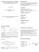
6.2 Rear Panel
4321 DCBACONTROL
RS232 DC 12V
USB
SERVICE
ONLY
HDMI IN HDMI OUT
1 2 3 4 5 6
1 HDMI IN 1/2/3/4: Connect to HDMI source devices such as DVD/
Blu-ray players or PCs/Laptops.
2 HDMI OUT A/B/C/D: Connect with HDMI equipped displays such as
HDTVs/Monitors.
3 CONTROL: Connect to an active network for telnet control (Please
refer to Section 6.6 for RS-232/Telnet).
4 USB SERVICE ONLY: Reserved for manufacturer use only.
5 RS-232: Connect to a PC/Laptop or RS-232 control system with a
D-Sub 15pin cable to control the device with RS-232 commands
(Please refer to Section 6.6 for RS-232/Telnet).
6 DC 12V: Connect the 12V DC power supply to the unit and plug
the adaptor into an AC outlet.

6
6.3 Remote Control
1 Power: Press to turn the unit ON or to put it into
standby mode.
2 Info: Press this button to show the device’s
rmware version.
3 Out A/B/C/D and In 1/2/3/4: Press output A~D
and then press input 1~4 to assign the display
input. For example: press Out A then press In 1,
output A will display the video from input 1.
4 Matrix/Dual/TV Wall: Press to switch between
Matrix mode, Dual mode and TV Wall mode.
5 Lock: Press once to lock the keypad and remote
control, press again and hold for 3 seconds to
release the lock function.
6 Mute: Press this button to mute the audio from the HDMI output.
7 ▲/▼/◄/►/OK: Press these buttons to navigate the OSD menu
and press OK to enter or conrm the settings.
8 Exit: Press this button to exit the OSD menu or the OSD settings.
9 Menu: Press this button to enter into the OSD menu.
10 1024x768/720p/1080p: Press the required button to switch to that
resolution.
11 Dual Audio AL/AR/BL/BR: When in Dual mode, press these hot keys
to switch the audio channel to the Left or Right side for Dual A and
Dual B groups.
12 Save: To save the customized input and output settings.
1) Press “Matrix/Dual/Wall” button to select the desired mode.
2) Press each output channel A~D and then press corresponding
input channel 1~4 as required.
3) Press “SAVE”, the input 1~4 LEDs will light at the same time,
then press one of the input 1,2,3 or 4 buttons to save the settings
to the system memory.
For example: Select Matrix mode, press output A then press
input 4, then press “SAVE”.
13 FAV.1/2/3/4: Press favorite key (1/2/3/4) to bring up the customized
saved screen settings.
CR-125
OK
Out A In 1Matrix
Info Power
Dual
TV Wall
Lock
Out B In 2
Out C In 3
Out D In 4
Mute
ExitMenu
Save1024x768 FAV.1
720p 1080pFAV.2
AL AR FAV.3
BL
Dual Audio
BR FAV.4
1
5
4
9
7
13
2
6
3
8
10
11
12

7
6.4 Remote Control Dip Switch
Open the Remote control back cover to adjust the dip-switch settings
(ON/OFF) to match the IR address setting in the OSD menu. Default
setting is 0.
1 2
ON
0
1 2
ON
1
1 2
ON
2
1 2
ON
3
6.5 RS-232 Protocols
HDMI SEAMLESS MATRIX
►
◄
REMOTE CONTROL
PIN Assignment PIN Assignment
1 NC 1 NC
2TxD 2RxD
3RxD 3TxD
4 NC 4 NC
5GND 5GND
6 NC 6 NC
7 NC 7 NC
8 NC 8 NC
9 NC 9 NC
Baud Rate: 115200bps
Data Bit: 8 bits
Parity: None
Flow Control: None
Stop Bit: 1

8
6.6 RS-232 and Telnet Control
Using PC software or Hyper terminal to congure the setting. This
software application can be downloaded from the product website.
Simple-function Control Panel:
Full-function Control Panel:
Telnet Setting:
The device can be controlled through Telnet over TCP/IP. Use Port
23 for Telnet communication. The Telnet connection settings can be
checked via the OSD menu or via RS-232 commands.

9
6.7 RS-232 and Telnet Commands
COM-
MAND
DESCRIPTION RESPONSE
AUA001 Dual A Audio channel in Left side AUA001
AUA002 Dual A Audio channel in Right side AUA002
AUA999 Check Dual A Audio channel status AUA???
AUB001 Dual B Audio channel in Left side AUB001
AUB002 Dual B Audio channel in Right side AUB002
AUB999 Check Dual B Audio channel status AUB???
AUD000 Audio output Off AUD000
AUD001 Audio output On AUD001
AUD999 Check Audio on/off status AUD???
AUE000 Audio EDID is LPCM 2CH AUE000
AUE001 Audio EDID is LPCM 6CH AUE001
AUE002 Audio EDID is LPCM 8CH AUE002
AUE003 Audio EDID is BITSTREAM AUE003
AUE004 Audio EDID is HD AUE004
AUE999 Check audio EDID setting AUE???
BEZ000 BEZEL CORRECTION Off BEZ000
BEZ001 BEZEL CORRECTION On BEZ001
BEZ999 Check BEZEL CORRECTION on/off status BEZ???
BEH??? Horizontal (H) Bezel Correction
???=000~Maximum
BEH???
BEH998 Check current Horizontal (H) Bezel
Correction maximum value
BEH???
BEH999 Check current Horizontal (H) Bezel
Correction setting value
BEH???

10
COM-
MAND
DESCRIPTION RESPONSE
BEV??? Vertical (V) Bezel Correction
???=000~Maximum
BEV???
BEV998 Check current Vertical (V) Bezel Correction
maximum value
BEV???
BEV999 Check current Vertical (V) Bezel Correction
setting value
BEV???
BRI??? BRIGHTNESS setting
- Matrix mode:
???=000~100
- Dual/TV Wall mode:
???=(000~100)+200×(OUT No.-1 e.g.
To set OUT B brightness value to 57, it is
(57)+200×(2-1)=257
No response
BRI99? Check current BRIGHTNESS value
99?=999 (Matrix mode)
99?=991~994=OUT1~4 (Dual/TV Wall mode)
BRI???
CAL??? Recall customized screen settings
???=001~004=FAV.1~4
CAL???
CON??? CONTRAST setting No response
CON999 Command setting as BRI??? CON???
EGW999 Check current Ethernet GATEWAY address
(RS-232 command only)
aaa.bbb.
ccc.ddd
EIP999 Check current Ethernet IP address (RS-232
command only)
aaa.bbb.
ccc.ddd
EMK999 Check current Ethernet SUBNET MASK
address (RS-232 command only)
aaa.bbb.
ccc.ddd
HUE??? HUE setting No response
HUE999 Command setting as BRI??? HUE???

11
COM-
MAND
DESCRIPTION RESPONSE
INP??? INPUT selection???=001~004=IN 1~4 INP???
Execute OUT???
INP999 Check current INPUT INP???
LCK000 Un-lock the keypad LCK000
LCK001 Lock the keypad LCK001
LCK999 Check current LOCK/UN-LOCK status LCK???
MNE001 OSD Menu EXIT No response
MND001 OSD Menu DOWN No response
MNL001 OSD Menu LEFT (-) No response
MNO001 OSD Menu OK No response
MNR001 OSD Menu RIGHT (+) No response
MNU001 OSD Menu UP No response
MNX001 OSD Menu No response
MOD001 Matrix mode MOD001
MOD002 Dual mode MOD002
MOD003 TV Wall mode MOD003
MOD999 Check current output mode status MOD???
OUT??? OUTPUT selection
???=001~004=OUT A~D
OUT???
OUT999 Check current OUTPUT OUT???
PWR000 Power off (Standby) PWR000
PWR001 Power on PWR001
PWR999 Check current POWER status PWR???
RES??? OUTPUT RESOLUTION setting
???=001~... corresponding to OSD menu
RES???
RES999 Check current OUTPUT RESOLUTION RES???
RST001 FACTORY reset RST001

12
COM-
MAND
DESCRIPTION RESPONSE
RST002 PICTURE reset RST002
SAT??? SATURATION setting No response
SAT999 Command setting as BRI??? SAT???
SAV??? Save customized screen settings
???=001~004=FAV.1~4
SAV???
VER999 Check FIRMWARE version e.g. VER110=V1.1 VER???
Note: Commands will be not executed unless followed with a carriage
return(0x0D).Commandsarecase-sensitive.

13
6.8 OSD Menu
MAIN MENU SUB MENU ADJUSTMENTS DEFAULT
PICTURE1
All
CONTRAST 0 ~ 100 50
BRIGHTNESS 0 ~ 100 50
SATURATION 0 ~ 100 50
HUE 0 ~ 100 50
Dual (D)
DUAL AL
DUAL AR
DUAL BL
DUAL BR
TV Wall (T)
OUT A
OUT B
OUT C
OUT D
D/T RESET
All
RESET ALL
EXIT
OUTPUT
RESOLUTION
480p 1024×768 720p60
576p 1280×800
720p50 1280×1024
720p60 1366×768
1080i5021440×900
1080i6021600×900
1080p24 1600×1200
1080p50 1680×1050
1080p60 1920×1200
EXIT

14
MAIN MENU SUB MENU ADJUSTMENTS DEFAULT
AUDIO EDID3LPCM 2CH LPCM
2CH
LPCM 6CH
LPCM 8CH
BITSTREAM
HD
EXIT
OSD SETTINGS POSITION LEFT T LEFT T
RIGHT T
LEFT B
RIGHT B
H OFFSET 0 ~ 20 10
V OFFSET 0 ~ 20 10
TRANSPARENCY 0 ~ 9 4
MENU TIMEOUT 5 ~ 50 8
OFF4
INFO. TIMEOUT 5 ~ 50 8
OFF
INFO. DISPLAY ON ON
OFF
BRIEF INFO ON OFF
OFF
EXIT
HDCP INPUT5ACCEPT ACCEPT
NOT ACCEPT
OUTPUT6FOLLOW INPUT FOLLOW
INPUTALWAYS ON
EXIT

15
MAIN MENU SUB MENU ADJUSTMENTS DEFAULT
BEZEL
CORRECTION7
CORRECTION ON OFF
OFF
H CORRECTION 0 ~ By Output
Resolution
0
V CORRECTION 0 ~ By Output
Resolution
0
EXIT
RECALL/SAVE8RECALL CANCEL CANCEL
FAV.1 ~ 4
SAVE CANCEL CANCEL
FAV.1 ~ 4
EXIT
ETHERNET IP MODE DHCP DHCP
STATIC
STATIC SET IP IP
MASK
GATE
BYTE1 192
BYTE2 168
BYTE3 5
BYTE4 155
RE-LINK9
TIMEOUT10 (Min.) 5~60 10
OFF
EXIT
OTHERS IR ADDRESS11 0 ~ 3 0
EXIT
/