Page is loading ...

DS-VWC2-4K22
4K Dual Input HDMI Video Wall Processor
with Warping and Rotation
OPERATION MANUAL


DISCLAIMERS
The information in this manual has been carefully checked and is
believed to be accurate. CYP (UK) Ltd assumes no responsibility for any
infringements of patents or other rights of third parties which may result
from its use.
CYP (UK) Ltd assumes no responsibility for any inaccuracies that may be
contained in this document. CYP (UK) Ltd also makes no commitment to
update or to keep current the information contained in this document.
CYP (UK) Ltd reserves the right to make improvements to this document
and/or product at any time and without notice.
COPYRIGHT NOTICE
No part of this document may be reproduced, transmitted, transcribed,
stored in a retrieval system, or any of its part translated into any language
or computer le, in any form or by any means—electronic, mechanical,
magnetic, optical, chemical, manual, or otherwise—without express
written permission and consent from CYP (UK) Ltd.
© Copyright 2021 by CYP (UK) Ltd.
All Rights Reserved.
Version 1.1
TRADEMARK ACKNOWLEDGMENTS
All products or service names mentioned in this document may be
trademarks of the companies with which they are associated.

SAFETY PRECAUTIONS
Please read all instructions before attempting to unpack, install or operate
this equipment and before connecting the power supply.
Please keep the following in mind as you unpack and install this
equipment:
• Always follow basic safety precautions to reduce the risk of re,
electrical shock and injury to persons.
• To prevent re or shock hazard, do not expose the unit to rain,
moisture or install this product near water.
• Never spill liquid of any kind on or into this product.
• Never push an object of any kind into this product through any
openings or empty slots in the unit, as you may damage parts inside
the unit.
• Do not attach the power supply cabling to building surfaces.
• Use only the supplied power supply unit (PSU). Do not use the PSU if
it is damaged.
• Do not allow anything to rest on the power cabling or allow any
weight to be placed upon it or any person walk on it.
• To protect the unit from overheating, do not block any vents or
openings in the unit housing that provide ventilation and allow for
sucient space for air to circulate around the unit.
REVISION HISTORY
REV. DATE SUMMARY OF CHANGE
RDV1 2020/09/04 Preliminary release
RDV2 2020/12/14 Add Phase 2 features: Chroma key, Cropping
RDV3 2020/12/28 Added Default and Preset Update to software

CONTENTS
1. Introduction ............................................................. 1
2. Applications ............................................................. 1
3. Package Contents .................................................... 1
4. System Requirements ............................................. 2
5. Features .................................................................... 2
6. Operation Controls And Functions......................... 3
6.1 Front Panel ........................................................................... 3
6.2 Rear Panel .............................................................................4
6.3 RS-232 Pinout and Defaults ........................................... 4
6.4 OSD Menu ............................................................................ 5
6.5 Video Wall Control Software ........................................26
6.5.1 Software Operation .............................................26
6.5.2 Video Wall Unit Search ........................................27
6.5.3 Basic Unit Settings & Conguration ...............29
6.5.4 I/O Conguration ..................................................30
6.5.5 Warping Mode Image Conguration ............32
6.5.6 Scaling Mode Image Conguration ...............33
6.5.7 Scaling Mode Layouts .........................................34
6.5.7.1 Window Tab ..................................................34
6.5.7.2 Cropping Tab ...............................................38
6.5.8 Warping Mode Layouts ......................................40
6.5.8.1 Pre-Dened Video Wall Layouts ............41
6.5.8.2 Customised Video Wall Layouts ............42

6.5.8.3 Multi-Zone Video Wall Layouts ..............45
6.5.9 Conguration Export/Import ...........................47
6.6 Telnet Control ....................................................................49
6.7 Serial and Telnet Commands .......................................49
7. Connection Diagram ............................................. 86
8. Specications ......................................................... 87
8.1 Technical Specications ................................................87
8.2 Video Specications........................................................88
8.3 Audio Specications .......................................................90
8.3.1 Digital Audio ..........................................................90
8.4 Cable Specications .......................................................90
9. Acronyms ................................................................ 91

1
1. INTRODUCTION
This UHD
+
2×1 HDMI Video Wall Rotation processor is capable of scaling
and rotating the selected input source to nearly any angle and size
desired. It’s the ideal solution for presenting sources across the unique
video display arrangements often found in commercial displays, control
rooms, or classrooms. HDMI input and output resolutions up to 4K@60Hz
with 2 channel LPCM audio is supported. In Warping mode the output
is locked to 4K, but video latency is only 1 to 2 frames and the unit is
capable of scaling and rotating the source, with an accuracy of 1°, as
required. In Scaling mode, the unit can scale to a wide selection of output
resolutions, up to 4K@60Hz, with independent PiP windows, outlines and
video mirror eects.
By combining multiple units with an HDMI splitter or matrix it is possible
to create fantastically varied arrangements of rotated displays for large
video wall applications. This is perfect for creating distinct and eye-
catching advertising or promotional displays limited only by your
imagination. Conguring these large video walls is made simple by use
of our Video Wall PC application, allowing the user to visually lay out
and congure the entire video wall at one time in a graphical WYSIWYG
user interface. A number of common video wall arrangement presets are
included with the software by default to make it possible to get started
quickly. Control of the unit is accomplished via front panel controls with
an OSD menu, Telnet, RS-232 or the Video Wall PC software.
2. APPLICATIONS
Public Commercial Displays
Demo Room Displays
Hotel Lobby Information Displays
Live Public Events
3. PACKAGE CONTENTS
1× UHD
+
2×1 HDMI Video Wall Rotation
1× 24V/2.7A DC Power Adapter
1× Shockproof Feet (Set of 4)
1× Operation Manual

2
4. SYSTEM REQUIREMENTS
HDMI source equipment such as media players, video game consoles
or set-top boxes.
HDMI receiving equipment such as an HDTV, monitor or audio
amplier.
5. FEATURES
HDMI 2.0 and DVI 1.0 compliant (with the use of an HDMI-DVI adapter)
HDCP 1.x and 2.2 compliant
2 HDMI inputs and 1 HDMI output
Supports up to 4K UHD
+
(18Gbps, 4K@50/60Hz 4:4:4, 8-bit) video input
and output
Only 1 to 2 frames of video latency
Supports horizontal/vertical video warping with zooming in/out and
360 degree display rotation in 1° increments (Warping mode)
Supports up to two simultaneous, freely scalable, PiP windows in multi-
windowing modes (Scaling mode)
Seamless switching (no loss of sync to display) when switching sources
with optional crossfade transition (Scaling mode)
Each window can have a border with a selectable colour (Scaling
mode)
Per-input video cropping and chroma key overlay (Scaling mode)
Wide variety of video adjustments, including: contrast, brightness, hue,
sharpness, aspect ratio
Supports the ability to store a multi-window or warping arrangement
as a preset that can be recalled later
Independent audio source selection and routing in all modes
Uploadable and freely positionable graphic logo support
Per-input EDID management with internal or external EDID options
Control of the unit is accomplished by use of front panel buttons with
OSD menu, Telnet, RS-232 or dedicated Video Wall PC software

3
6. OPERATION CONTROLS AND FUNCTIONS
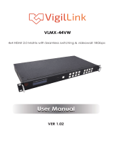
6.1 Front Panel
SERVICE POWER
1080P
SCALE MODE
ROTATE
OSD
SCALE
ROTATE
INFO.
XGA
-
+
MENU
ENTER
WIN 1/IN 1 WIN 2/IN 2 OSD INFO.
WARPING
ON/OFF
SOURCE
SELECT
1 2
3 4
5
6 7
8 9
DS-VWC2-4K22
1
SERVICE Port: This port is reserved for rmware update and user
EDID/logo upload use only.
2
POWER LED: This LED will illuminate green to indicate the unit is on
and receiving power. When the unit is in stand-by mode the LED will
illuminate red.
3
POWER Button: Press this button to power the unit on or place it into
stand-by mode.
Note: Ethernet and RS-232 remain active when the unit is in stand-by
mode.
4
SCALE & ROTATE LEDs: One of these LEDs will illuminate to indicate
the unit’s current operational mode.
5
MODE Button: Press this button to toggle between Scaling mode
(Scale) and Warping mode (Rotate).
6
MENU Button: Press to enter the OSD menu, or to back out from
menu items.
Note: When in Scaling mode, pressing “MENU” and “+” together will reset
the output resolution to XGA (1024×768@60Hz). Pressing “MENU” and “-”
together will reset the output resolution to 1080p@60Hz.
7
WIN 1/IN 1 & − (MINUS) & WARPING ON/OFF Button:
Menu Operation: When in a menu, press to move down or adjust
selections within OSD menus.
Scaling Mode: Press to switch window 1’s source in multi-
windowing modes or to select input 1 in Switcher mode.
Warping Mode: Press to enable or disable warping functionality.
8
WIN 2/IN 2 & − (PLUS) & SOURCE SELECT Button:
Menu Operation: When in a menu, press to move up or adjust
selections within OSD menus.
Scaling Mode: Press to switch window 2’s source in multi-
windowing modes or to select input 2 in Switcher mode.
Warping Mode: Press to select the input source.

4
9
OSD INFO & ENTER Button:
Menu Operation: When in a menu, press to conrm a selection
within the OSD or to go deeper into a menu item.
Scaling/Warping Mode: Press to display information about the
unit on the OSD including details about video, audio and Ethernet.
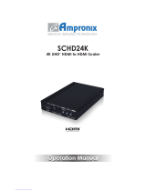
6.2 Rear Panel
12
HDMI OUTHDMI IN
CONTROLRS-232 DC 24V
1 2
3 4
5
1
HDMI IN 1~2 Ports: Connect to HDMI source equipment such as
media players, game consoles, or set-top boxes.
2
HDMI OUT Port: Connect to an HDMI TV, monitor, or amplier for
digital video and audio output.
3
CONTROL Port: Connect directly, or through a network switch, to
your PC/laptop to control the unit via the control software or Telnet.
4
RS-232 Port: Connect directly to a PC, laptop, or other serial control
device with a 3.5mm adapter cable to send RS-232 commands to
control the unit or control it via the control software.
5
DC 24V Port: Plug the 24V DC power adapter into this port and
connect it to an AC wall outlet for power.
6.3 RS-232 Pinout and Defaults
Serial Port Default Settings
Baud Rate 19200
Data Bits 8
Parity Bits None
Stop Bits 1
Flow Control None
3.5mm to DE-9
Adapter Cable
RxD
TxD
GND
1
2
3

5
6.4 OSD Menu
All functions of this unit can be controlled by using the OSD (On Screen
Display) which is activated by pressing the MENU button on the front of
the unit. Use the + (PLUS), − (MINUS), and ENTER buttons to navigate the
OSD menu. Press the MENU button to back out from any menu item and
then press it again to close the menu.
MAIN MENU
Video Mode
Window/Warping Lay-
out
Chroma Key
Window Cropping
Picture
Audio
Input EDID
HDCP Mode
Output Resolution
OSD Settings
Logo Settings
Ethernet
Preset
Setup
Information
The individual functions of the OSD will be introduced in the following
section. Items marked in BOLD are the factory default settings.

6
VIDEO MODE
2ND LEVEL 3RD LEVEL
Display Func SCALING
Warping
Scaling Mode
Video Mode Switcher
PIP
PoP
Preset 1
Preset 2
Preset 3
Preset 4
Transition
(Switcher Only)
OFF
Cross Fade
Out Source
(Switcher Only)
IN 1
In 2
Win 1 Source
(Pip/PoP/Preset)
IN 1
In 2
Win 2 Source
(Pip/PoP/Preset)
In 1
IN 2
Warping Mode
Warping Preset WARPING
Preset 1
Preset 2
Preset 3
Preset 4

7
VIDEO MODE
2ND LEVEL 3RD LEVEL
Output Source IN 1
In 2
Warping On/O On
OFF
Fixed Angle 0~359 (0)
1) Display Func: Set the unit’s overall operation mode to either Scaling
mode or Warping mode.
Note: Each mode’s video settings are independent of each other and some
functions are only available in a single mode.
2) Video Mode: Select the preferred operation mode of the unit while in
Scaling mode.
Note: Selecting Switcher mode will restrict the output to a single full
screen window. All other modes may have up to 2 windows. All changes
made to the video/audio output conguration are automatically saved to
the currently selected preset.
3) Transition: Enable or disable the use of a cross fade transition when
changing sources in Scaling mode’s Switcher mode.
4) Out Source: Select the source for the HDMI output while in Scaling
mode’s Switcher mode.
5) WIN 1/2 Source: Select the source for the specied window when in
multi-windowing modes (PiP, PoP, Preset 1~4).
6) Warping Preset: Select the warping preset to congure.
Note: All changes made to the video/audio output conguration are
automatically saved to the currently selected preset.
7) Output Source: Select the source for the HDMI output while in
Warping mode.
8) Warping On/O: Enable or disable warping functionality for the
video output. Enabling warping allows for the creation of video walls.
Note: Certain features, such as Fixed angle are only available when
warping is disabled.

8
9) Fixed Angle: Allows for the full screen source to be rotated to the
specied angle.
Note: Changing this setting will automatically disable warping mode.
WINDOW LAYOUT (Scaling Mode Only)
2ND LEVEL 3RD LEVEL
Input Select
(Switcher Only)
IN 1
In 2
Window Select
(Pip/PoP/Preset)
WIN 1
Win 2
Window On/O ON
O
Position X 0~Max H Resolution
Position Y 0~Max V Resolution
Size Width 0~Max H Resolution
Size Height 0~Max V Resolution
Priority 1~2 (2)
Aspect Ratio FULL
16:9
16:10
4:3
Best Fit
User
(Pip/PoP/Preset only)
Center
(Rotation only)
Mirror On
OFF

9
WINDOW LAYOUT (Scaling Mode Only)
2ND LEVEL 3RD LEVEL
Rotation (Switcher
Only)
On
OFF
Border On/O On
OFF
Border Color Black
Red
GREEN
Blue
Yellow
Magenta
Cyan
White
Dark Red
Dark Green
Dark Blue
Dark Yellow
Dark Magenta
Dark Cyan
Gray
Window Reset NO
Yes
1) Input Select: Select the input to modify.
Note: Only available in Switcher mode. All settings are individually saved,
per-input.
2) Window Select: Select the window to modify.

10
Note: Only available in multi-windowing modes. All settings are
individually saved, per-window/per-mode.
3) Window On/O: Enable or disable the currently selected window.
Note: Only available in multi-windowing modes.
4) Position X/Y: Set the X and Y coordinate position of the upper left
corner of the currently selected window.
Note: Only available in multi-windowing modes.
5) Size Width/Height: Set the horizontal and vertical size of the currently
selected window.
Note: Only available in multi-windowing modes.
6) Priority: Select the layer priority of the currently selected window.
Priority 1 is at the front and priority 2 is at the back.
Note: Only available in multi-windowing modes.
7) Aspect Ratio: Select a xed aspect ratio for the currently selected
window. The aspect ratio will be based on the window’s current
height. Selecting the “Full” aspect ratio will return the window to the
current mode’s default size and shape for that window. Selecting
“Best Fit” will automatically set the ratio based on the window’s
current source resolution. Selecting “Center” will t the rotated source
completely within the display while maintaining the original aspect
ratio.
Note: The “Custom” aspect ratio is not available in the Switch preset. The
“Center” aspect ratio is only available when rotation is active and the
input/output resolutions are not both 4K.
8) Mirror: Selecting “On” will ip the currently selected window
horizontally.
Note: Only available in the Switch preset when rotation is disabled.
9) Rotation: Selecting “On” will rotate the output 90 degrees
counterclockwise and stretch it to ll the display.
Note: Only available in the Switch preset. Rotation is not available if
cropping is enabled.
10) Border On/O: Enables or disable the colour border around the
currently selected window.
11) Border Color: Select the colour to use for the border of the currently
selected window.
12) Window Reset: Reset the current window to its default settings based
on the currently selected mode.

11
WARPING LAYOUT (Warping Mode Only)
2ND LEVEL 3RD LEVEL
Warping Select [Currently selected preset]
Keep Aspect Ratio ON
O
Warping Left -1767~3687 (960)
Warping Top -972~2007 (540)
Warping Width 1536~3840 (1920)
Warping Height 864~2160 (1080)
Warping Angle 0~359 (45)
Warping Bezel L 0~255 (0)
Warping Bezel R 0~255 (0)
Warping Bezel T 0~255 (0)
Warping Bezel B 0~255 (0)
4C Top Left
[Current X/Y coordinates
of each corner of the
warped crop within the
selected source]
4C Top Right
4C Bom Left
4C Bom Right
Warping Reset NO
Yes
1) Warping Select: Displays which warping preset is currently active.
2) Keep Aspect Ratio: Enables or disables forcing the current aspect
ratio to be maintained when the display is resized by changing the
warping width or height.
3) Warping Left/Top: Sets the pixel position of the top/left corner of the
pre-rotated display within the currently selected source.
Note: If the Warping Angle value is changed, this value will not change
and will continue to match the location of the display prior to rotation

12
in order to simplify manual positioning. Due to the complexities of
rotational warping, the unit performs the additional calculations to
generate the true locations of each corner of the display, as shown by the
“4C” values, so that unintended distortion can be avoided.
4) Warping Width/Height: Sets the horizontal and vertical size of the
display, within the currently selected source, in pixels.
5) Warping Angle: Sets the rotation angle of the display in degrees.
6) Warping Bezel L/R/T/B: Sets the left, right, top, and bottom bezel
measurements of the display in units relative to the size of the display.
7) 4C Top Left/Top Right/Bom Left/Bom Right: Displays the computed
X/Y pixel coordinates for each of the 4 corners of the display, within
the current source.
8) Warping Reset: Reset all warping output settings to their defaults.
CHROMA KEY (Scaling Mode Only)
2ND LEVEL 3RD LEVEL
Chroma Key On
OFF
User Select USER 1
User 2
User 3
User 4
White
Yellow
Cyan
Green
Magenta
Red
Blue
Black

13
CHROMA KEY (Scaling Mode Only)
2ND LEVEL 3RD LEVEL
Red Max 0~255 (255)
Red Min 0~255 (0)
Green Max 0~255 (255)
Green Min 0~255 (0)
Blue Max 0~255 (255)
Blue Min 0~255 (0)
1) Chroma Key: Enable or disable the chroma key function. When
enabled, input 1 becomes the top layer which has the keying values
applied to it while input 2 is the bottom layer.
Note: Only available when in Scaling mode with Switcher mode active.
2) User Select: Select the keying preset to apply when the chroma key
function is enabled.
Note: Only presets User 1~4 can be manually adjusted. All other presets
are xed value combinations.
3) Red Max/Min: Set the maximum and minimum values for the chroma
key’s red component.
4) Green Max/Min: Set the maximum and minimum values for the
chroma key’s green component.
5) Blue Max/Min: Set the maximum and minimum values for the
chroma key’s blue component.
WINDOW CROPPING (Scaling Mode Only)
2ND LEVEL 3RD LEVEL
In1/Win1 Cropping Enable On
OFF
In1/Win1 Cropping H-Start 0~3840 (320)
In1/Win1 Cropping H-Width 0~3840 (1280)
In1/Win1 Cropping V-Start 0~2160 (180)

14
WINDOW CROPPING (Scaling Mode Only)
2ND LEVEL 3RD LEVEL
In1/Win1 Cropping V-Height 0~2160 (720)
In1/Win1 Cropping Reset NO
Yes
In2/Win2 Cropping Enable On
OFF
In2/Win2 Cropping H-Start 0~3840 (320)
In2/Win2 Cropping H-Width 0~3840 (1280)
In2/Win2 Cropping V-Start 0~2160 (180)
In2/Win2 Cropping V-Height 0~2160 (720)
In2/Win2 Cropping Reset NO
Yes
1) In1/Win1 Cropping Enable: Enable or disable cropping for input 1
(Switcher mode) or window 1 (PiP/PoP/Preset modes).
Note: Cropping settings are stored independently for every mode/preset.
2) In1/Win1 Cropping H-Start/H-Width: Set the horizontal starting
pixel and relative horizontal width for the video content to display.
Note: Values are applied to the native resolution of the incoming source
being cropped, not the scaled output resolution or window size.
3) In1/Win1 Cropping V-Start/V-Height: Set the vertical starting pixel
and relative vertical height for the video content to display.
Note: Values are applied to the native resolution of the incoming source
being cropped, not the scaled output resolution or window size.
4) In1/Win1 Cropping Reset: Reset all cropping settings for the current
mode/input/window to their factory defaults.
5) In2/Win2 Cropping Enable: Enable or disable cropping for input 2
(Switcher mode) or window 2 (PiP/PoP/Preset modes).
Note: Cropping settings are stored independently for every mode/preset.
/