Moxa TCC-100 Series User’s Guide
Rx+
CTS+
CTS
-
RTS+
RTS
-
SGND
Rx
-
Tx+
Tx
-
Tx+(B)
RTS+(B)
RTS
-(A)
CTS+(B)
CTS
-(A)
SGND
Tx
-(A)
Rx+(B)(Data+)
Rx
-(A)(Data-)
Optiona
RS-422
When using the RS-422 wiring option, first
follow the 4-wire RS-485 wiring instructions
given above.
Optional RTS/CTS Handshaking Signals
If your software is set up to send and receive
RTS/CTS signals over separate wires, you
should also connect from RTS+(B) to CTS+,
from RTS-(A) to CTS-, from CTS+(B) to
RTS+, and from CTS-(A) to RTS-.
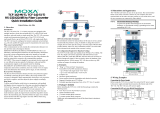
STEP 4: Attach the RS-232
Connector
Depending on your application,
use the appropriate serial cable to
connect from CC-100/100I’s
RS-232 Female DB9 port to your
RS-232 device, or to your
computer’s COM port.
5 4 3 2 1
9 8 7 6
Female DB9
PIN RS-232
1 ---
2 TxD
3 RxD
4 ---
5 GND
6 ---
7 CTS
8 RTS
9 ---
RS-232 Pin Assignment Diagram
STEP 5: Test the Connection
After setting the DIP Switches, connecting the power, wiring the terminal block,
and attaching the RS-232 connector, we suggest using a Console Terminal
program, such as HyperTerminal or Moxa Terminal Emulator, to test the
connection. If you have an RS-422/485 serial board (such as Moxa CP-132, a
2-port RS-422/485 board) installed in your PC, you can connect your PC’s COM
port to TCC-100 Series’s RS-232 port, and then connect TCC-100 Series’s
RS-422/485 terminal block to one of the RS-422/485 serial board’s ports.
Alternatively, if you have already set up an RS-422 or RS-485 network, you can
also connect TCC-100 Series’s RS-422/485 terminal block directly to that
network. Next, start HyperTerminal or Moxa Terminal Emulator, and then open a
connection to both the COM port, and the port associated with TCC-100 Series’s
RS-422/485 port. Simply type a few characters on your PC’s keyboard. The
characters you type should show up in the HyperTerminal window that is
currently inactive, indicating that the typed characters were transmitted between
TCC-100 Series’s RS-232 port and RS-422/485 terminal block connector.
2-6