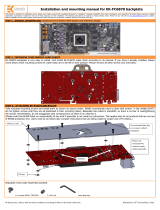
All disclosures, notices and warranty conditions are being written on the back of the box. Released on 18
h
of May, 2011.
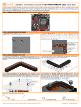
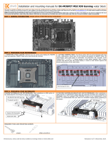
STEP 3: PREPARING YOUR WATER BLOCK
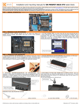
1. ATTACHING STANDOFFS. Apply small amount of thermal grease around mounting
holes and place acetal standoffs on NB & MOSFET part of the waterblock (thickness 2,1
mm) so the holes are concentric. Use two 3,3mm acetal standoffs on the SB part of the
waterblock to make one 6,6mm standoff. Thermal paste provides enough adhesive force
for standoffs to stay in a place for easier installation. This is a crucial step!
2. PLACING BLOCK OVER MB. Place the motherboard on the inverted water blocks
or vice versa and attach them with enclosed screws as shown. Make sure that
mounting holes are aligned.
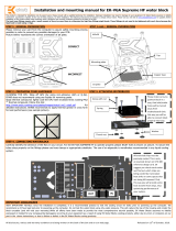
STEP 4: ATTACHING BLOCK TO MOTHERBOARD
MOUNTING THE BLOCK.
For
perfect thermal contact, the block does not use a spring mounting system; therefore when attaching be very careful to tighten all screws equally.
Tightening the screws beginning in the center of the block near the northbridge, and continue evenly outwards. Do not use too much pressure
on
screws, because motherboard might
bend and either cause bad contact with water block, or break a connection on the circuit board.
Use the enclosed screws and washers as shown in diagram below:
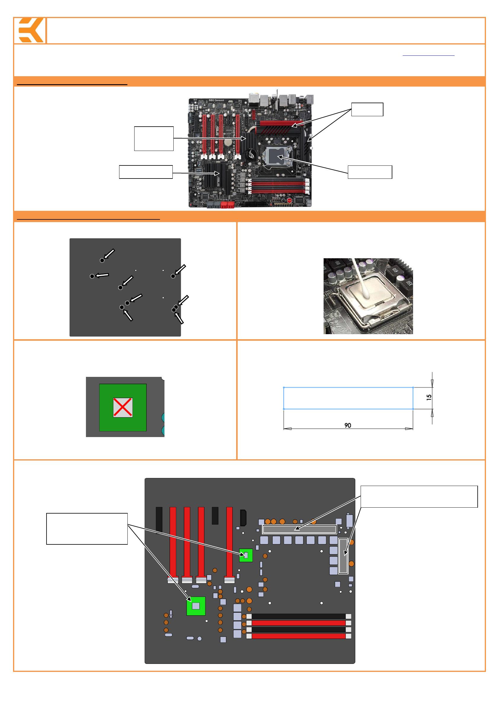
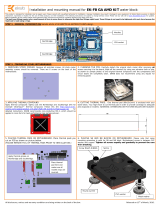
STEP 5: CHECKING FOR CONTACTS
Temporarily r
emove the water block to check for uniform surface contact between the block and the components. Note the pattern of contact on a piece of paper. Then repeat
steps 3 and 4 to reattach the block. Block was tested on physical hardware. Due to height variations of chipset some differences may occur. In case you have problem with block
contacts please write to our support mail.
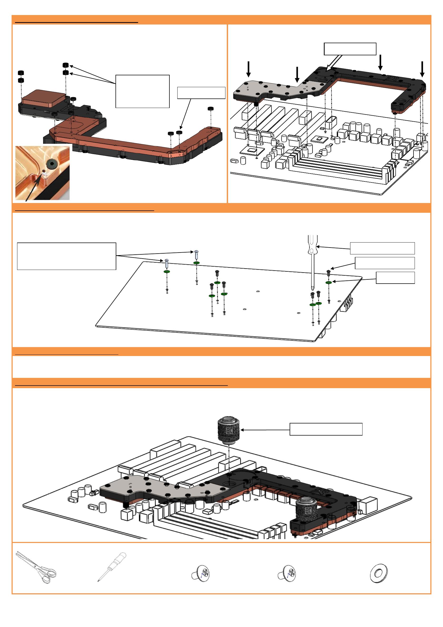
STEP 6: POSITIONING FITTINGS AND CONNECTING TO WATER CIRCUIT
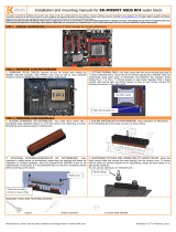
Screw in fittings as shown in picture, attach the liquid cooling tubes and connect the water-block(s) into the cooling circuit. Please use spacer if you use fitting with G1/4 thread
longer than 5mm. Attach the liquid cooling tubes and connect the water-block(s) into the cooling circuit. EKWB recommends using EK-PSC compression fittings with the EK-FB
Max4 Extreme series water blocks. The use of an market proved algaecide is always recommended for any liquid cooling system. You can use any opening as an inlet/outlet
port.
REQUIRED TOOLS AND MOUNTING SCREWS:
scissors philips screwdriver 6 screws M2.5x6 DIN7985 2 screws M3x12 DIN7985 8 PVC washers
EK-PSC compression fitting
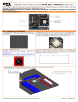
Two 3,3mm
standoffs combined
on the SB part of
the waterblock
Use two (2) enclosed M3x12 DIN7985
screws on the southbridge part of the
waterblock!