Page is loading ...

This product is intended for installation only by expert users. Please consult with a qualified technician for installation. Improper installation may result in damage to your equipment. EK Water Blocks assumes no liability
whatsoever, expressed or implied, for the use of these products, nor their installation. The following instructions are subject to change without notice. Please visit our web site at www.ekwaterblocks.com for updates.
Before installation of this product please read important notice, disclosure and warranty conditions printed on the back of the box.
The barb hose fittings require only a small amount of force to screw them in; otherwise the high flow fittings might break. These fittings do not need to be tightened with much force because the
liquid seal is made using o-rings.
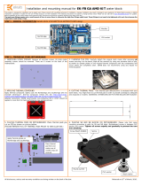
STEP 1: GENERAL INFORMATION Sam
p
le
p
hoto of ASUS CROSSHAIR III FORMULA PCB desi
g
n
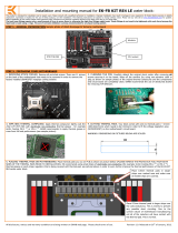
STEP 2: PREPARING YOUR MOTHERBOARD
1. REMOVING STOCK COOLER. Remove all encircled screws. All stock
cooler assembly screws should be removed. There are 6 screws on the back of
the motherboard.
2. CLEANING THE PCB. Carefully detach the original stock cooler after removing all screws
securing it to the board. Wipe off the remains (by using non–abrasive cloth or qtip, as shown
on sample photo) of the original thermal compound until the components and circuit board are
completely clean. EKWB does not recommend using any liquids for removing paste.
3. APPLYING THERMAL COMPOUND
Apply thermal compound: lightly coat the Northbridge and Southbridge with
for example Céramique™ thermal compound. Follow this link
http://www.arctic-
cooling.com/catalog/product_info.php?cPath=39_&mID=127&language=en for
detailed instructions. EKWB recommends non-conductive MX-2, which should
be applied in cross form for best performance (see sample picture).
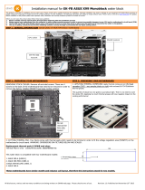
4. CUTTING THERMAL PADS. One thermal pad (90x15x1 mm) and one thermal pad
(90x7,5x1 mm) are enclosed with your water block. You will have to cut out parts from smaller
thermal pad in order to cover all the surfaces that are left exposed on mosfets. (WARNING:
DIMENSIONS ON PICTURES BELLOW ARE SCALED!)
5. PLACING THERMAL PADS ON MOTHERBOARD. Place thermal pads you cut on PCB as shown on picture bellow.
(PLEASE REMOVE FOIL OF THERMAL PADS PRIOR TO INSTALLATION.)
Installation and mounting manual for EK-FB ASUS CROSSHAIR 3 water block:
Alldisclosures,noticesandwarrantyconditionsarebeingwrittenonthebackofthebox. Releasedon7thofAugust,2009.
Southbridge
Northbridge
Mosfets
CPUsocket
Apply thermal grease on
Northbridge and Southbridge. Place thermal pads here and make sure
all mosfet chips are covered.

STEP 3: PREPARING YOUR WATER BLOCK
1. ATTACHING STANDOFFS. Apply small amount of thermal grease around mounting holes
and place acetal standoffs (thickness 2,5 mm) so the holes are concentric. Thermal paste
provides enough adhesive force for standoffs to stay in a place.
2. PLACING BLOCK OVER GPU. Place the motherboard on the inverted water
block or vice versa and attach it with enclosed screws as shown. Make sure that
mounting holes are aligned.
STEP 4: ATTACHING BLOCK TO MOTHERBOARD
1. MOUNTING THE BLOCK.
For
perfect thermal contact, the block does not use a spring mounting system; therefore when attaching be very careful to tighten all screws equally.
Tightening the screws beginning in the center of the block near the northbridge, and continue evenly outwards. Do not use too much pressure
on
screws, because motherboard might
bend and either cause bad contact with water block, or break a connection on the board.
Use the enclosed screws and washers as shown in diagram below:
STEP 5: CHECKING FOR CONTACTS
Temporarily r
emove the water block to check for uniform surface contact between the block and the components. Note the pattern of contact on a piece of paper. Then repeat
steps 3 and 4 to reattach the block applying more or less pressure to the areas where you have found it necessary.
STEP 6: POSITIONING FITTINGS AND CONNECTING TO WATER CIRCUIT
1.Screw in fittings as shown in photo, attach the liquid cooling tubes and connect the water-block(s) into the cooling circuit. The EK-FB ASUS CROSSHAIR III FORMULA series
are usually sold with high flow fittings. To ensure that the tubes are securely attached to the barb fittings, please use hose clamps or an appropriate substitute. The use of an
algaecide is always recommended for any liquid cooling system.
You can use any hole as an inlet/outlet hole. Please make sure spacer in installed in hole as shown bellow.
REQUIRED TOOLS AND MOUNTING SCREWS:
scissors philips screwdriver 6 screws M3x6 DIN7985
Alldisclosures,noticesandwarrantyconditionsarebeingwrittenonthebackofthebox. Releasedon7thofAugust,2009.
Fitting/barb
Spacer
Washer
M3x6 screw
washer
Please use the enclosed insulating
washers on all M3x6mm screws.
/