Page is loading ...

OPERATION MANUAL
P/N: 49103
Revision #1 (08/15/08)
NIGHTHAWK SERIES
MODELS LT-12D, LT-12P
DEDICATED LIGHT TOWER
(DEUTZ/LOMBARDINI DIESEL ENGINE)
(PERKINS DIESEL ENGINE)
THIS MANUAL MUST ACCOMPANY THE EQUIPMENT AT ALL TIMES.
To find the latest revision of this
publication, visit our website at:
www.multiquip.com

PAGE 2 — LT-12 SERIES LIGHT TOWER — OPERATION MANUAL — REV. #1 (08/15/08)
Diesel engine exhaust and some of
PROPOSITION 65 WARNING / REPORTING SAFETY DEFECTS
REPORTING SAFETY DEFECTS
If you believe that your vehicle has a defect that could cause a crash or could cause injury or
death, you should immediately inform the National Highway Traffic Safety Administration
(NHTSA) in addition to notifying Multiquip at 1-800-421-1244.
If NHTSA receives similar complaints, it may open an investigation, and if it finds that a safety
defect exists in a group of vehicles, it may order a recall and remedy campaign. However,
NHTSA cannot become involved in individual problems between you, your dealer, or
Multiquip.
To contact NHTSA, you may either call the Vehicle Safety Hotline toll-free at 1-888-327-4236
(TTY: 1-800-424-9153), go to http://www.nhtsa.dot.gov; or write to:
Administrator
NHTSA
1200 New Jersey Avenue S.E.
Washington, DC 20590
You can also obtain information about motor vehicle safety from http://www.safecar.gov.

LT-12 SERIES LIGHT TOWER — OPERATION MANUAL — REV. #1 (08/15/08) — PAGE 3
TABLE OF CONTENTS
STOW NIGHTHASTOW NIGHTHA
STOW NIGHTHASTOW NIGHTHA
STOW NIGHTHA
WKWK
WKWK
WK
LL
LL
L
TT
TT
T
-12 SERIES LIGHT TOWER-12 SERIES LIGHT TOWER
-12 SERIES LIGHT TOWER-12 SERIES LIGHT TOWER
-12 SERIES LIGHT TOWER
Proposition 65 ................................................................. 2
Reporting Safety Defects ................................................ 3
Table of Contents............................................................. 3
Safety Message Alert Symbols ................................... 4-5
Rules For Safe Operation ............................................. 6-7
Operation and Safety Decals ........................................ 8-9
Specifications (Light Tower) ........................................... 10
Specifications (Engines) ................................................ 11
Dimensions .................................................................... 12
General Information ....................................................... 13
Components .............................................................. 14-15
Control Panel ............................................................. 16-17
Floodlight Footcandle Plots ........................................... 18
Towing Guidelines ...................................................... 19-20
Trailer Safety Guidelines ............................................ 21-22
Trailer Wiring Diagram .................................................... 23
Inspection ..................................................................24-27
Startup Procedure ......................................................... 28
Shutdown Procedure ..................................................... 29
Mast Operation .............................................................. 30
Operation ....................................................................... 31
Maintenance .............................................................. 32-36
Troubleshooting (Generator) ........................................... 37
Troubleshooting (Engine) ...........................................38-39
Troubleshooting (Lamps) ............................................ 40-42
Schematic Diagram ....................................................... 43
Deutz Engine Wiring ...................................................... 44
Perkins Engine Wiring .................................................... 45
For Deutz/Lombardini Parts
information, please see our LT-12
Deutz F3M1008F Diesel Engine
Parts Manual.
NOTE

PAGE 4 — LT-12 SERIES LIGHT TOWER — OPERATION MANUAL — REV. #1 (08/15/08)
Safety precautions should be followed
at all times when operating this
equipment. Failure to read and
understand the Safety Messages and
Operating Instructions could result in
injury to yourself and others.
FOR YOUR SAFETY AND THE SAFETY OF OTHERS!
This Owner's Manual has been
developed to provide complete
instructions for the safe and
efficient operation of the
LT-12 Series Light Tower.
Before using this Light Tower, ensure that the operating
individual has read and understands all instructions in this
manual.
SAFETY MESSAGE ALERT SYMBOLS
The three (3) Safety Messages shown below will inform you
about potential hazards that could injure you or others. The
Safety Messages specifically address the level of exposure
to the operator, and are preceded by one of three words:
DANGER, WARNING, or CAUTION.
HAZARD SYMBOLS
Potential hazards associated with the
LT-12 Series Light
Tower
operation will be referenced with Hazard Symbols
which appear throughout this manual, and will be referenced
in conjunction with Safety Message Alert Symbols.
NOTE
LT-12 SERIES LIGHT TOWER — SAFETY MESSAGE ALERT SYMBOLS
Engine exhaust gases contain
poisonous carbon monoxide. This gas
is colorless and odorless, and can
cause death if inhaled. NEVER operate
this equipment in a confined area or
enclosed structure that does not provide
ample free flow air.
Diesel fuel is extremely flammable, and
its vapors can cause an explosion if ignited.
DO NOT start the engine near spilled fuel
or combustible fluids.
DO NOT fill the fuel tank while the engine is running or
hot. DO NOT overfill tank, since spilled fuel could ignite if
it comes into contact with hot engine parts or sparks from
the ignition system. Store fuel in approved containers, in
well-ventilated areas and away from sparks and flames.
Engine components can generate extreme
heat. To prevent burns, DO NOT touch
these areas while the engine is running or
immediately after operations. Never
operate the engine with heat shields or heat
guards removed.
WARNING - Lethan Exhaust Gasses
You WILL be
KILLED
or
SERIOUSLY
injured if you DO
NOT follow directions.
You CAN be
KILLED
or
SERIOUSLY
injured if you DO
NOT follow directions.
You CAN be
INJURED
if you DO NOT follow directions.
DANGER
WARNING
CAUTION
WARNING - Explosive Fuel
WARNING - Burn Hazards
ALWAYS wear approved
respiratory
protection when required.
CAUTION - Respiratory Hazard

LT-12 SERIES LIGHT TOWER — OPERATION MANUAL — REV. #1 (08/15/08) — PAGE 5
Other important messages are provided throughout this
manual to help prevent damage to your light tower, other
property, or the surrounding environment.
NOTE
ALWAYS place the power source, circuit
breakers or ON/OFF switch in the OFF
position, when the generator is not in use,
unless connected to transfer switch.
NEVER tamper with the factory settings of
the engine governor settings. Personal injury
and damage to the engine or equipment can
result if operating speed ranges above
maximum allowable.
ALWAYS wear approved eye and
hearing protection.
LT-12 SERIES LIGHT TOWER — SAFETY MESSAGE ALERT SYMBOLS
This light tower, other
property, or the surrounding
environment could be
damaged if you
do not
follow
instructions.
NEVER operate equipment with covers,
or guards removed. Keep fingers, hands,
hair and clothing away from all moving
parts to prevent injury.
CAUTION - Rotating Parts
CAUTION - Accidental Starting
CAUTION - Sight and Hearing Hazards
CAUTION - Over-Speed Conditions
CAUTION - Equipment Damage Messages

PAGE 6 — LT-12 SERIES LIGHT TOWER — OPERATION MANUAL — REV. #1 (08/15/08)
LT-12 SERIES LIGHT TOWER — RULES FOR SAFE OPERATION
■
ALWAYS refuel in a well-ventilated area, away from sparks
and open flames.
■
ALWAYS use extreme caution when
working with flammable liquids. When
refueling, stop the engine and allow it to
cool. DO NOT
smoke around or near the
machine. Fire or explosion could result from
fuel vapors, or if fuel is spilled on a hot engine.
■
NEVER operate the light tower/generator in an explosive
atmosphere or near combustible materials. An explosion or
fire could result causing severe
bodily harm or even death.
■
Topping-off to filler port is dangerous, as it tends to spill fuel.
■
ALWAYS make sure that the light tower/generator is secure
on level ground so that it cannot slide or shift around,
endangering workers. Also keep the immediate area free of
bystanders.
■
ALWAYS use a
trained technician
to install and remove a
floodlight, or replace any damaged fixture wiring.
■
NEVER leave any grease or oil residue on glass surface
when replacing or removing bulbs. This can create hot spots,
reducing the service life of the bulb or causing outer jacket
to burst.
■
ALWAYS make sure trailer is leveled with all outriggers
extended before raising tower. Outriggers must remain
extended while tower is up.
■
ALWAYS keep area behind trailer clear of people while
raising and lowering mast.
■
NEVER remove safety pin or pull mast locking pin while
tower is in an raised position!
■
CHECK the mast and winch cables for wear. If any problem
occurs when lower or raising the tower STOP immediately!
Contact a trained technician for assistance.
■
NEVER pivot or retract mast while unit is operating.
■
The engine of this light tower/generator requires an adequate
free flow of cooling air. NEVER operate the generator in any
enclosed or narrow area where free
flow of the air is restricted. If the air
flow is restricted it will cause serious
damage to the generator engine
and may cause injury to people.
Remember the engine of the light
tower/generator gives off DEADLY
carbon monoxide gas.
WARNING - READ THIS MANUAL
Failure to follow instructions in this manual may lead to
Serious Injury
or even
Death
. This equipment is to be
operated by trained and qualified personnel only! This
equipment is for industrial use only.
The following safety guidelines should always be used
when operating the LT-12 Lighttower.
Safety
■
DO NOT operate or service this equipment
before reading this entire manual.
■
This equipment should not be operated
by persons under 18 years of age.
■
NEVER operate this equipment without
proper protective clothing, shatterproof glasses,
steel-toed boots and other protective devices
required by the job.
■
NEVER operate this equipment when not
feeling well due to fatigue, illness or taking
medicine.
■
NEVER operate the saw under the
influence or drugs or alcohol.
■
NEVER use accessories or attachments, which are not
recommended by Stow for this equipment. Damage to the
equipment and/or injury to user may result.
■
Manufacturer does not assume responsibility for any accident
due to equipment modifications. Unauthorized equipment
modification will void all warranties.
■
Whenever necessary, replace nameplate, operation and
safety decals when they become difficult read.
■
ALWAYS check all the bolts on the light tower for tightness.
■
NEVER touch the hot exhaust manifold,
muffler or cylinder. Allow these parts to
cool before servicing engine or
generator.
■
High Temperatures – Allow the engine
to cool before adding fuel or performing service and
maintenance functions. Contact with
hot
components can
cause serious burns.

LT-12 SERIES LIGHT TOWER — OPERATION MANUAL — REV. #1 (08/15/08) — PAGE 7
LT-12 SERIES LIGHT TOWER — RULES FOR SAFE OPERATION
The
5 DANGER
items listed below are considered
High DANGER
areas and should be adhered to. Failing to
understand these areas could result in
Bodily Harm,
Electrical
Shock
,
Electrocution
, and even
Death! Please
pay close attention when operating the light tower.
The LT-12 Light tower is equipped with
a
ground terminal
for your protection.
ALWAYS complete the
grounding
path
from the light tower to an external
grounding source.
ALWAYS make certain the light tower is well grounded and
securely fastened to a good earth ground (ground rod). The
possibility exists of
Electrical Shock, Electrocution, and
even Death
if the light tower is not grounded.
NEVER operate the LT-12 Light tower
or handle any electrical equipment
while standing in water, while bare
foot, while hands are wet, or in the
rain. A dangerous
electrical shock
could occur causing
Severe Bodily Harm or even Death.
ALWAYS keep electrical cords in good condition. Worn,
bare or frayed wiring can cause electrical shock, thus
causing
Bodily Harm or even Death
.
NEVER grab or touch a live power
cord with wet hands, the possibility
exists of
Electrical Shock,
Electrocution, and even Death!
POWER
CORD
(POWER ON)
WET
HANDS
ALWAYS make sure the area
above Light tower is open
and clear of overhead power
lines and other obstructions.
The tower extends in excess
of 30 ft. (9 meters). Contact
with overhead powerlines or
other obstructions could result
in equipment damage,
Serious Injury or Death
!
■
NEVER touch bulbs while in use. Bulbs become extremely
hot when in use! Allow bulbs and fixture to cool at least 10-
15 minutes before handling.
■
ALWAYS retract the mast before lowering the tower to
transport position.
Maintenance Safety
■
NEVER lubricate components or attempt service on a running
light tower/generator.
■
ALWAYS allow the light tower/generator a proper amount of
time to cool before servicing.
■
Keep the light tower/generator in proper running condition.
■
Fix damage to the light tower/generator immediately and
always replace broken parts.
Emergencies
■
ALWAYS know the location of the
nearest
fire extinguisher
.
■
ALWAYS know the location of the nearest
first aid kit
.
■
In emergencies
always
know the location of the nearest phone
or
keep a phone on the job site
. Also know the phone
numbers of the nearest
ambulance
,
doctor
and
fire
department
. This information will be invaluable in the case
of an emergency.
■
NEVER use the light tower mast as a crane. DO NOT lift
anything with the mast.
■
NEVER attach anything to the light tower mast.
■
ALWAYS keep the immediate area surrounding the light
tower clean, neat, and free of debris.
■
ALWAYS lower the tower when not in use, or if high winds or
electrical storms are expected in the area.
■
NEVER pivot or retract mast while unit is operating.
DANGER - High Danger Areas
DANGER - Grounding the LT-12 for Operation
DANGER - Electric Shock Hazards
DANGER - Overhead Obstruction Danger

PAGE 8 — LT-12 SERIES LIGHT TOWER — OPERATION MANUAL — REV. #1 (08/15/08)
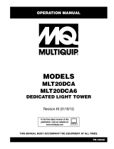
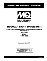
Machine Safety Decals
This dedicated light tower is equipped with a number of safety decals. These decals are provided for operator safety and maintenance
information. The illustration below and on the next page shows these decals as they appear on the machine. Should any of these
decals become unreadable, replacements can be obtained from your dealer.
LT-12 SERIES LIGHT TOWER — OPERATION AND SAFETY DECALS
Figure 1. Operation and Safety Decals

LT-12 SERIES LIGHT TOWER — OPERATION MANUAL — REV. #1 (08/15/08) — PAGE 9
LT-12 SERIES LIGHT TOWER — OPERATION AND SAFETY DECALS
Figure 1. Operation and Safety Decals (Continued)

PAGE 10 — LT-12 SERIES LIGHT TOWER — OPERATION MANUAL — REV. #1 (08/15/08)
LT-12 SERIES LIGHT TOWER — SPECIFICATIONS (LIGHT TOWER)
SNOITACIFICEPS.1ELBAT
ledoMrewoTthgiL
D21-TLP21-TL
ledoMenignE
/F8001m3FztueD
3001WDLinidrabmoL
enignEleseiD
01-301snikreP
enignEle
seiD
)yrD(thgieW ).gk007(.sbl055,1
snoisnemiD3elbaTeeS
stnioPtroppuS5
.tesneGhtiwytilibatSdniW )hpk64.08(hpm5
6
sthgildoolF edilaHlateMttaW000,1-4
snemuL000,044
egarevoCthgiL serca7ot5
noitanimreTthgiL gulpDQnip-3x4
snoi
tacificepSrotareneG
tuptuOelcatpeceRICFG )ylnoSU(A51@CAV021
tuptuOelcatpeceRkcoL-tsiwT )ylnoSU(A52@CAV042
)spmA(rekaerBtiucriCICFGA51
)spmA(rekaerBtiucriCkcoL-tsiwTA52
)sttaW(tuptuOsuounitnoCW000,6
)m7(.tf32@leveL
esioN.bd37
noitacificepSreliarT
yticapaCdnatskcaJ ).gk709(.sbl000,2
epyThctiH )elbiliavatiKeltniPlanoitpO(l
laB.ni2
eziSeriT ).mm033(.ni31
eziSmiReriT )mm411x033(.ni5.4x31
yticapaCelxA ).gk709(.sbl000,2
epyTbuHguL-5
ep
yTnoisnepsuSfaeL-3
rotcennoCthgil-liaTlacirtcelEeriW-4
yticapaChcniW ).gk086(.sbl005,1
eriWepoRhcniW.ni61/3

LT-12 SERIES LIGHT TOWER — OPERATION MANUAL — REV. #1 (08/15/08) — PAGE 11
LT-12 SERIES LIGHT TOWER — SPECIFICATIONS (ENGINES)
snoitacificepSenignE.2elbaT
ledoMsnikreP
leseiD01-301
enignE
epyTenignE enignEleseiDretil1,rednilyc-3,ekorts-4detaripsA
ekortSXeroB )mm
27xmm57(.ni38.2X.ni59.2
tnemecalpsiD )cc459(.ni.uc12.85
ybdnatStuptuOxaM .M.P.R008,1ta.P.H21
emirPtuptuOxa
M .M.P.R008,1ta.P.H5.01
yticapaCknaTleuF )sretiL311(snollaG.S.U03.xorppA
sthgiL4htiWemiTnuRsruoH46
deepSeld
IdradnatS.M.P.R008,1
epyTleuFleuFleseiD2.0N
yticapaCliOebuL )sretiL5.3(stniP.S.U4.7
metsySgnilooCdelooc-reta
W
yticapaCtnalooC )sretiL8.3(stniP.S.U0.8
dohteMgnitratStratScirtcelE
epyTyrettaB21puorG
)yrD(thgieWlatoT).gK
721(.sbl082
)teW(thgieWlatoT).gK031(.sbl782
inidrabmoL
WDLledoM
leseiD/3001
enignE
ro
ledoMztueD
F800M3F
enignE
leseiD
epyTenignE enignEleseiD,rednilyc-3
tnemecalpsiD )cc8201(.ni.uc37.26
ybdnatStuptuOxaM .M.P.R008,1ta.P
.H21
yticapaCknaTleuF )sretiL311(snollaG.S.U03.xorppA
sthgiL4htiWemiTnuRsruoH46
deepSeldIdradnatS.M.P.R008,
1
epyTleuFleuFleseiD2.0N
yticapaCpmuSliO )sretiL63.2(strauQ.S.U5.2
metsySgnilooCdelooc-diuqiL
dohteMgnitratSt
ratScirtcelE
epyTyrettaB42puorG
)yrD(thgieWlatoT).gK58(.sbl3.781

PAGE 12 — LT-12 SERIES LIGHT TOWER — OPERATION MANUAL — REV. #1 (08/15/08)
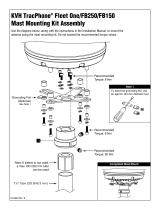
LT-12 SERIES LIGHT TOWER — DIMENSIONS
Figure 2. Dimensions
SNOISNEMID.3ELBAT
retteLecnerefeRnoitpircseD).mm(.ninoisnemiD
A)noitisoPdewotStsaM(htgneL).mc134(.ni071
B)noitisoPdeyolpeDtsaM
(htgneL).mc652(.ni101
C)noitisoPdeyolpeDtsaM(thgieH.xaM)m6.9(.tf5.13
D)noitisoPdewotStsaM(thgieH).mc781(.ni4
7
E)elxAmorF(ecnaraelCdnuorG).mc02(.ni8
F)ydaeRwoT(htdiW).mc921(.ni15
G)deyolpeDsreggirtuO(htdiW).mc672(.ni901

LT-12 SERIES LIGHT TOWER — OPERATION MANUAL — REV. #1 (08/15/08) — PAGE 13
LT-12 SERIES LIGHT TOWER — GENERAL INFORMATION
The Stow LT-12 Series Light Tower is a dedicated general
purpose floodlight tower intended for emergency and remote
lighting conditions.
The light tower can be raised vertically in excess of 31.5 feet
(9.6 meters) by means of a manual winch. The tower tensioning
system is designed to provide the necessary tension to safely
control the pivot of the tower. Outriggers and rear support stand
must be deployed prior to raising the mast.
The lighting system of Stow's LT-12 Series Light Tower is
comprised of 4 "Metal Halide" 1000 watt lamps. Each lamp has
an output of 110,000 lumens yielding a total of 440,000 lumens
for all four floodlights. Typical lighting coverage is between 5 to 7
acres.
Each floodlight requires a ballast for starting. Located on the
control panel of the generator is a weather resistant ballast box
that the contains the ballast for each floodlight. The control panel
contains four ON/OFF circuit breakers for each floodlight.
For ease of service or transport, each floodlight is equipped
with a quick-disconnect connector that allows the lamp fixture to
be removed quickly. This feature is extremely useful during
transport of the light tower over rough terrain. It is always best to
remove the floodlights and pack them safely so they will not get
damaged.
As an added feature, the LT-12 is available with two auxiliary
output receptacles. The upper most receptacle(twist-lock),
located at the front of the light tower, can provide 240 VAC at 25
amps. The bottom receptacle is a GFCI receptacle which can
supply 120 VAC at 15 amps. These receptacles that can be used
for light power tools or other similar applications.
NOTE
Some LT-12 Light towers are
equipped with a Lombardini
Diesel Engine. All procedures &
references to Deutz engines in
this manual may be applied to
Lombardini engines unless
specifically noted otherwise.
ALWAYS make sure the area
above Light tower is open and
clear of overhead power lines
and other obstructions. The
tower extends in excess of 30
ft. (9 meters). Contact with
overhead powerlines or other
obstructions could result in
equipment damage,
Serious
Injury or Death
!
DANGER - Overhead Obstruction Danger

PAGE 14 — LT-12 SERIES LIGHT TOWER — OPERATION MANUAL — REV. #1 (08/15/08)
LT-12 SERIES LIGHT TOWER — COMPONENTS
Figure 3 and 4 shows the location of the controls and components
for the LT-12 Series Light Tower. The functions of each control is
described below:
1. Mast Rotation Locking Knob – Unscrew this knob to
release mast for rotation.
2. Vertical Mast Extension Winch – Use this winch to extend
the mast to the desire height. Maximum height is approxi-
mately 31.5 feet (9.6 meters).
3. Mast Rotation Handle – Grip this handle to rotate mast to
desired position. To lock mast tighten mast rotation locking
knob.
4. Lifting Bail – When lifting of the light tower by crane is
required, use this lifting bail. Note: this lifting bail is balanced
for a
fully configured
light tower; removal of any light tower
components will un-balance the lifting bail.
5. Forklift Pockets – When lifting of the light tower is required,
use these fork lift pockets to lift the light tower. Remember to
insert the forks of the fork lift a minimum of 24 inches into the
mast fork lift pockets.
6. Mast Cradle Support – When towing of the light tower is
required, place the tower mast into the cradle support. Make
sure tower release pin has been inserted and mast is locked.
7. T-Bar – Allows the floodlights to be mounted vertically or
horizontally.
8. Flood Light – 1000 watt "Metal Halide" type bulb with a
110,000 lumens capacity. Light coverage is typically be-
tween 5 to 7 acres.
Figure 3. Major Components (Control Panel Side)
9. Tower Lock/Release Pin – Pull this pin to release tower
mast from cradle support.
10. Jack Stands – There are two trailer jack stands, which are
located at the front and rear of the trailer. Use these 2 jack
stands to level and support the light tower.
11. Chock Blocks – Place these blocks (not included as part of
the light tower package) under each trailer wheel to prevent
rolling.
12. Outrigger Jacks – Use these 2 outrigger jacks to level and
support the light tower.
13. Control Panel/ Ballast Compartment – This panel con-
tains the ON/OFF circuit breakers for each flood light. In
addition, located behind the control panel are the ballasts
and electrical components for each floodlight.
14. Safety Chain – Always attach safety chain to the towing
vehicle. Never tow the light tower with the safety chain
unattached.
15. Ball Hitch Coupler – Attach this coupler to the towing
vehicle. Use only the specified ball diameter as indicated on
your coupler. Use of any other ball diameter will create an
extremely dangerous condition which can result in separa-
tion of the coupler and ball or ball failure.
16. Vertical Mast Winch – Use this winch to raise the mast the
to the vertical position. Once mast is in the full vertical position
the locking pin engages automatically.
17. Mast Locking/Release Pin – Pull this pin to start placing the
tower mast in the vertical position.
Locking pin automatically
engages when tower mast has reached full vertical position.

LT-12 SERIES LIGHT TOWER — OPERATION MANUAL — REV. #1 (08/15/08) — PAGE 15
LT-12 SERIES LIGHT TOWER — COMPONENTS
18. Engine Exhaust Pipe – Directs engine exhaust to the rear
of the light tower. NEVER block this exhaust pipe with obstruc-
tions. ALWAYS place the generator in an area free of
obstructions.
Figure 4. Major Components (Front/Rear)
19. License Light – This light illuminates the license plate.
Whenever towing of the light tower is required, make sure this
light is operational.
20. Brake Lights – Before towing the light tower, make sure that
these lights are operational and are working correctly. NEVER
tow the light tower if these lights are inoperative.
The exhaust pipe will become extremely hot
when the engine is in use. NEVER touch the
exhaust pipe when the engine is running. The
possibility exists of severe burns to the skin.
Allow the exhaust pipe to
cool
before
touching.
21. Tires – This light tower uses a ST175-13C size tire. Replace
with only recommended tire size. NEVER tow light tower with
bad or worn tires.
22. Documentation Box – Contains information regarding the
light tower.
23. 240 VAC Twist-Lock Receptacle – This twist-lock recep-
tacle provides 240 VAC, 25 amps.
24. 120 VAC GFCI Receptacle – This GFCI receptacle provides
120 VAC, 15 amps.
CAUTION - Burn Hazard

PAGE 16 — LT-12 SERIES LIGHT TOWER — OPERATION MANUAL — REV. #1 (08/15/08)
LT-12 SERIES LIGHT TOWER — CONTROL PANEL
Figure 5. Control Panel Components and Indicators

LT-12 SERIES LIGHT TOWER — OPERATION MANUAL — REV. #1 (08/15/08) — PAGE 17
1. Internal Cabinet Light Switch – This switch controls the
internal cabinet light for the light tower control panel. When
the cabinet door is raised, the light will automatically come
on. When the cabinet door closes, the switch is depressed
and the light turns off.
2. Internal Cabinet Light – Provides illumination for the LT-
12 control panel during nighttime operation. The light is
activated when the cabinet door is raised.
3. Hour Meter – This digital hour meter indicates the number
of hours machine has been in use.
4. Main Circuit Breaker – A double-pole 25 amp, ON/OFF
circuit breaker which protects the 240 VAC twist-lock
receptacle from overload. In addition it allows voltage to be
supplied to the GFCI receptacle and 15 amp breakers (4).
5. GFCI Receptacle Circuit Breaker – A single-pole, 15
amp, ON/OFF circuit breaker which protects the GFCI
receptacle from overload.
6. Flood Light Circuit Breakers – A single-pole, 15 amp,
ON/OFF circuit breaker for each floodlight (4).
Figure 5 shows the location of the basic control panel components
for the LT-12 Light Tower. Listed below is a brief explanation of
each control or component.
Items 7 - 11 refer to the
Perkins Engine Control
Panel only. See Figure 5.
7. Air Filter Indicator Alarm Light – This alarm light flashes
when a problem with the air filter is detected. Service as
required.
8. Water Temperature Alarm Light – This alarm light flashes
when the water temperature becomes to hot for normal
engine operation. Service as required.
9. Oil Pressure Alarm Light – This alarm light flashes when
the oil pressure has fallen to low for normal engine
operation. Service as needed.
LT-12 SERIES LIGHT TOWER — CONTROL PANEL
10. Pre-Heat Indicator Light/Battery Charge Light –
Indicates when the glow plugs have been heated up for
starting the engine. If the light is flashing, a low battery
charge is detected.
11. Ignition Key Switch – Insert key into ignition switch and
turn clockwise to the ON position to warm the glow plugs.
When glow plug indicator light goes OFF, turn the key to
the START position. Release key when engine starts.
Items 12 - 18 refer to the
Lombardini Engine
Control Panel only. See
Figure 5.
12. Normal Operation Indicator Light – This
indicator light is illuminated when the engine is
functioning normally.
13. Low Oil Shutdown Indicator Light – This
indicator light is illuminated when the engine
has shut down due to low oil pressure. Service
as needed.
14. High Temperature Indicator Light – This
indicator light is illuminated when the engine has
shut down due to high water temperature. Service
as needed.
15. Alternator Indicator Light – This indicator light
is illuminated when the engine has shut down
due to high water temperature. Service as
needed.
16. Glow Plug Indicator Light – This indicator light
is illuminated when the glow plugs have been
heated for starting the engine.
17. Air Filter Restriction Indicator Light – This
indicator light is illuminated when the engine
has shut down due to blockage in the air filter.
Service as needed.
18. Ignition Key Switch – Insert key into ignition
switch and turn clockwise to the ON position to
warm the glow plugs. When glow plug indicator
light goes OFF, turn the key to the START position.
Release key when engine starts.
OK

PAGE 18 — LT-12 SERIES LIGHT TOWER — OPERATION MANUAL — REV. #1 (08/15/08)
LT-12 SERIES LIGHT TOWER — FLOOD LIGHT FOOTCANDLE PLOT
Figure 6. Floodlight Footcandle Plot (Area Coverage)

LT-12 SERIES LIGHT TOWER — OPERATION MANUAL — REV. #1 (08/15/08) — PAGE 19
LT-12 SERIES LIGHT TOWER — TOWING GUIDELINES
To reduce the possibility of an accident while transporting the
light tower on public roads, always make sure that the trailer and
the towing vehicle are in good operating condition and both
units are mechanically sound.
The following list of suggestions should be used when towing
the light tower:
Towing Safety Precautions
Check with your county or state safety towing regulations
department before towing your
light tower
.
■
Make sure that the hitch and coupling of the towing vehicle
are rated equal to, or greater than the trailer "gross vehicle
weight rating" (GVWR). See Table 1 for light tower weight.
■
ALWAYS inspect the hitch and coupling for wear. NEVER
tow the light tower's trailer with defective hitches, couplings,
chains etc.
■
CHECK the tire air pressure on both the towing vehicle and
the trailer. Also check the tire tread wear on both vehicles.
■
ALWAYS make sure the trailer section of the light tower is
equipped with a "Safety Chain".
■
ALWAYS attach trailer's safety chain to frame of towing
vehicle.
■
ALWAYS make sure that the vehicle and trailer directional,
backup, brake, and trailer lights are connected properly and
are working properly.
■
Remember in most cases the maximum speed unless
otherwise posted for highway towing is 55 MPH, however
before towing your light tower, check your local state, and
county vehicle towing requirements. Recommended off-road
towing is not to exceed 15 MPH or less depending on type of
terrain.
■
Place
chocked blocks
underneath wheel to prevent
rolling,
while parked.
■
Depending on soil conditions and location it may be
necessary to place
support blocks
underneath the trailer's
bumper to prevent
tipping
, while parked.
Light Tower Trailer Vehicle Connection
1. Check the vehicle hitch ball, and trailer coupler for signs of
wear or damage. Replace any parts that are worn or
damaged before towing.
2. Use only the 2-inch ball diameter as indicated on the trailer's
coupler. Use of any other ball diameter will create an
extremely dangerous condition which can result in
separation of the coupler and ball or ball failure.
3. Be sure the coupler is secured to the hitch ball and the lock
lever is down (locked).
4. Attach safety chains as shown in Figure 7. Remember to
cross
the safety chains.
5. After towing for about 50 miles recheck the entire towing
system for tightness.
Recommended Maintenance
1. Smear ball socket and clamp face with chassis grease.
Periodically oil pivot points and wear surfaces of the coupler
with SAE 30 W motor oil.
2. When parking or storing the light tower, keep the coupler off
the ground so dirt and other debris will not build up in the
ball socket.
If the trailer coupler is deformed replace entire coupler. NEVER
tow the light tower with a defective trailer coupler. There exist
the possibility of the trailer separating from the towing vehicle.
■
Check wheel mounting lug nuts with a torque wrench.
Torque wheel lug nuts as described in the "
Lug Nut Torque
Requirements
", Table 5.
■
Check tightness of hanger bolt, shackle bolt, and U-blots
nuts, torque suspension hardware per Table 4.
■
Avoid sudden stops and starts. This can cause skidding, or
jackknifing. Smooth, gradual starts and stops will improve
gas milage.
■
Avoid sharp turns to prevent rolling.
■
Swivle all jackstands parallel to the ground before
transporting.
■
DO NOT transport light tower with fuel in the generator fuel
tank.
Remember, when transporting of the
light tower is required,
always
remove the floodlights
and pack
them safely so they will not get
damaged.
NOTE
■
Inflate tires to correct pressure, inspect tires for cuts, and
excessive wear. See Table 3 (Tire Wear Troubleshooting).
CAUTION - Local Towing Regulations
CAUTION - Defective/Damaged Trailer Couplings

PAGE 20 — LT-12 SERIES LIGHT TOWER — OPERATION MANUAL — REV. #1 (08/15/08)
Figure 7. Safety Chains/ Trailer Coupler Hook-up
LT-12 SERIES LIGHT TOWER — TOWING GUIDELINES
/