Page is loading ...

OPERATION MANUAL
THIS MANUAL MUST ACCOMPANY THE EQUIPMENT AT ALL TIMES.
To find the latest revision of this
publication, visit our website at:
www.multiquip.com
MODEL LT6K5 50 HZ
LIGHT TOWER/GENERATOR
(KOHLER KDW 1003 DIESEL ENGINE)
Revision #0 (06/02/15)
PN 34910

PAGE 2 — LT6K5 50 HZ LIGHT TOWER • OPERATION MANUAL — REV. #0 (06/02/15)
FUEL CHEMICAL WARNING
Diesel engine exhaust and some of
its constituents are know to cause
cancer, birth defects and other
reproductive harm.

LT6K5 50 HZ LIGHT TOWER • OPERATION MANUAL — REV. #0 (06/02/15) — PAGE 3
TABLE OF CONTENTS
LT6K5 50 Hz Light Tower
Fuel Chemical Warning ........................................... 2
Table Of Contents .................................................... 3
Safety Information .............................................. 4-13
Lamp Footcandle Plot ............................................ 14
Specifications ................................................... 15-16
Dimensions ............................................................ 17
General Information ............................................... 18
Components ..................................................... 20-22
Control Panel .................................................... 23-24
Engine Components .............................................. 25
Inspection ......................................................... 26-28
Setup ................................................................ 29-32
Operation .......................................................... 33-35
Maintenance ..................................................... 36-42
Maintenance — Trailers .................................... 43-44
Safety Guidelines — Trailers ............................ 45-58
Troubleshooting (Generator) .................................. 59
Troubleshooting (Engine) .................................. 60-61
Troubleshooting (Lamps) .................................. 62-64
Panel Light/Hour Meter Wiring Diagram ................ 66
Electronic Components Locator ............................ 67
Wiring Diagram (Generator/Lights) .................. 68-69
Lights Locator Diagram ......................................... 70
Lights Wiring Diagram ........................................... 71

PAGE 4 — LT6K5 50 HZ LIGHT TOWER • OPERATION MANUAL — REV. #0 (06/02/15)
SAFETY INFORMATION
Do not operate or service the equipment before reading the
entire manual. Safety precautions should be followed at all
times when operating this equipment. Failure to read and
understand the safety messages and operating instructions
could result in injury to yourself and others.
SAFETY MESSAGES
The four safety messages shown below will inform you
about potential hazards that could injure you or others. The
safety messages specifi cally address the level of exposure
to the operator and are preceded by one of four words:
DANGER, WARNING, CAUTION
or NOTICE.
SAFETY SYMBOLS
DANGER
Indicates a hazardous situation which, if not avoided,
WILL result in DEATH or SERIOUS INJURY.
WARNING
Indicates a hazardous situation which, if not avoided,
COULD result in DEATH or SERIOUS INJURY.
CAUTION
Indicates a hazardous situation which, if not avoided,
COULD result in MINOR or MODERATE INJURY.
NOTICE
Addresses practices not related to personal injury.
SAFETY SYMBOLS
Potential hazards associated with the operation of this
equipment will be referenced with hazard symbols which
may appear throughout this manual in conjunction with
safety messages.
Lethal exhaust gas hazards
Explosive fuel hazards
Burn hazards
Overspeed hazards
Rotating parts hazards
Symbol Safety Hazard
Pressurized fluid hazards
Electric shock hazards

LT6K5 50 HZ LIGHT TOWER • OPERATION MANUAL — REV. #0 (06/02/15) — PAGE 5
SAFETY INFORMATION
DECALS
Decals associated with the operation of this equipment are
defi ned below.
can burn skin.
touch . Allow machine a
sufficient amount time to cool before performing
maintenance.
HOT PARTS
DO NOT hot parts
CAUTION
Burn Hazard
To avoid injury you must read and understand
operator’s manual before using this machine.
Hot steam or coolant may escape when radiator
cap is removed, causing severe burns.
Allow radiator to cool before removing cap.
WARNING
WARNING
Read Manual
Explosion Hazard
DECAL
Forklift point right.
NOTICE
Forklift point left.
NOTICE
P/N 23808
Lift Point. Attach lifting strap to this point
NOTICE
DEFIINITION
DO NOT remove panel when machine is on.
Possibility of electrocution exists causing
severe bodily harm even death!
DANGER
Electrocution Hazard
P/N 34620
Maintenance service to be performed by a
trained qualified electrician. Possibility of
electrocution exists causing severe bodily harm
even death!
DANGER
Electrocution Hazard
P/N 34621
DO NOT remove panel when machine is on.
Possibility of electrocution exists causing
severe bodily harm even death!
Maintenance service to be performed by a
trained qualified electrician. Possibility of
electrocution exists causing severe bodily harm
even death!
DANGER
High Voltage Hazard
Keep hands clear. Moving parts can crush
and pinch.
WARNING
Crush/Pinch Hazard
P/N 34622
DECAL
P/N 34629
P/N 34628
WARNING
Shear Hazard
Keep hands and fingers clear from engine
fan blades. Moving parts can cut.
remove guards.DO NOT
WARNING
Crush Hazard
Keep hands and fingers clear from engine
V-belt/pulley. Moving parts can cut.
remove guards.DO NOT
DO NOT light matches around or near this
equipment. This equipment contains highly
flammable fuel. If ignited, could start a
causing equipment damage and severe
bodily harm even death!
fire
DANGER
Fire Hazard
DO NOT smoke around or near this
equipment. This equipment contains highly
flammable fuel. If ignited, could start a
causing equipment damage and severe
bodily harm even death!
fire
DANGER
Fire Hazard
DEFIINITION
DO NOT use this equipment in an .
The engine used with this equipment emits
harmful levels of carbon monoxide which can
cause severe bodily harm even death!
enclosed area
DANGER
Inhalation Hazard
WARNING
Guard Hazard
operate equipment with guards
removed. Serious bodily injury could result.
DO NOT
Earth ground connection point. Connect a ground
rod or building ground to this connection point.
GROUNDING
P/N 34632
P/N 23813
The engine used in this equipment requires
or equivalent.No.2 diesel fuel
FUEL TYPE

PAGE 6 — LT6K5 50 HZ LIGHT TOWER • OPERATION MANUAL — REV. #0 (06/02/15)
SAFETY INFORMATION
GENERAL SAFETY
CAUTION
NEVER operate this equipment without proper protective
clothing, shatterproof glasses, respiratory protection,
hearing protection, steel-toed boots and other protective
devices required by the job or city and state regulations.
NEVER operate this equipment when not
feeling well due to fatigue, illness or when
under medication.
NEVER operate this equipment under the infl uence of
drugs or alcohol.
ALWAYS check the equipment for loosened threads or
bolts before starting.
DO NOT use the equipment for any purpose other than
its intended purposes or applications.
DECAL
DEFIINITION
Turn mast locking knob counterclockwise
to release mast. Grab hold of forklift pocket
and rotate mast to desired position. Tighten
mast locking knob.
MAST ROTATION
P/N 34631
JACK STANDS
Before towing,
rotate jack stands to the
stow position ().
ALWAYS
UP
NOTICE
This equipment should only be operated by trained and
qualifi ed personnel 18 years of age and older.
Whenever necessary, replace nameplate, operation and
safety decals when they become diffi cult read.
Manufacturer does not assume responsibility for any
accident due to equipment modifi cations. Unauthorized
equipment modifi cation will void all warranties.
NEVER
use accessories or attachments that are not
recommended by Multiquip for this equipment. Damage
to the equipment and/or injury to user may result.
ALWAYS know the location of the nearest
fi re extinguisher.
ALWAYS know the location of the nearest
fi rst aid kit.
ALWAYS
know the location of the nearest phone or
keep a phone on the job site.
Also, know the phone
numbers of the nearest ambulance, doctor and
fi re
department.
This information will be invaluable in the
case of an emergency.
LIGHT TOWER SAFETY
DANGER
NEVER
operate the equipment in an explosive atmosphere
or near combustible materials. An explosion or fi re could
result causing severe bodily harm or even death.
WARNING
NEVER disconnect any
emergency or safety devices.
These devices are intended for operator safety.
Disconnection of these devices can cause severe injury,
bodily harm or even death. Disconnection of any of these
devices will void all warranties.

LT6K5 50 HZ LIGHT TOWER • OPERATION MANUAL — REV. #0 (06/02/15) — PAGE 7
SAFETY INFORMATION
CAUTION
NEVER lubricate components or attempt service on a
running machine.
ALWAYS ensure light tower is on level ground before use
so that it cannot slide or shift around, endangering workers.
Always keep immediate area free of bystanders.
ALWAYS make sure trailer is leveled with all outriggers
extended before raising tower. Outriggers must remain
extended while tower is up.///////
ALWAYS keep area behind trailer clear of people while
raising and lowering mast.
NEVER remove safety latch or pull mast locking latch
while tower is in a raised position!
CHECK the mast and winch cables for wear. If any
problem occurs when lowering or raising the tower, STOP
immediately! Contact a trained technician for assistance.
NEVER pivot or retract mast while unit is operating.
NEVER use the light tower mast as a crane. DO NOT
lift anything with the mast.
NEVER attach anything to the light tower mast.
ALWAYS lower the light tower when not in use, or if high
winds or electrical storms are expected.
NOTICE
ALWAYS keep the immediate area surrounding the light
tower clean, neat, and free of debris.
ALWAYS keep the machine in proper running condition.
Fix damage to machine and replace any broken parts
immediately.
ALWAYS store equipment properly when it is not being
used. Equipment should be stored in a clean, dry location
out of the reach of children and unauthorized personnel.
To prevent the light tower from overturning, NEVER use
in winds that exceed 65 mph (105 kph).
LAMP SAFETY
WARNING
NEVER
attempt to replace lamp with the power on.
Always shut down the engine and turn off circuit breakers
when changing the lamp.
ALWAYS
allow a suffi cient amount of time for the lamp to
cool
before touching or changing. The possibility exists of
severe burns.
CAUTION
NEVER
use force when installing the lamp. Excessive
force could cause the lamp to break, causing bodily harm.
NOTICE
NEVER
leave any grease or oil residue on lamp surface
when replacing or removing lamp. This can create hot
spots, reducing the service life of the lamp.
ALWAYS make sure lamp surface is clean and dry.
ALWAYS replace with MQ recommended type lamp.
ALWAYS have a trained technician
install and remove
a fl oodlight, or replace any damaged fi xture wiring.
ENGINE SAFETY
DANGER
The engine fuel exhaust gases contain poisonous carbon
monoxide. This gas is colorless and odorless, and can
cause death if inhaled.
The engine of this equipment
requires an adequate free
fl ow of cooling air. NEVER
operate this equipment in
any enclosed or narrow area
where free fl ow of the air is
restricted. If the air fl ow is
restricted it will cause injury to people and property and
serious damage to the equipment or engine.
DANGEROUS
GASFUMES

PAGE 8 — LT6K5 50 HZ LIGHT TOWER • OPERATION MANUAL — REV. #0 (06/02/15)
SAFETY INFORMATION
WARNING
DO NOT place hands or fingers inside engine
compartment when engine is running.
NEVER operate the engine with heat shields or
guards removed.
Keep fi ngers, hands hair and clothing away
from all moving parts to prevent injury.
DO NOT remove the radiator cap while the engine is hot.
High pressure boiling water will gush out of the radiator
and severely scald any persons in the general area of
the generator.
DO NOT remove the coolant drain plug
while the engine is hot. Hot coolant will
gush out of the coolant tank and severely
scald any persons in the general area of
the generator.
DO NOT remove the engine oil drain plug while the
engine is hot. Hot oil will gush out of the oil tank and
severely scald any persons in the general area of the
generator.
CAUTION
NEVER touch the hot exhaust manifold,
muffl er or cylinder. Allow these parts to cool
before servicing equipment.
NOTICE
NEVER run engine without an air fi lter or with a dirty air
fi lter. Severe engine damage may occur. Service air fi lter
frequently to prevent engine malfunction.
NEVER tamper with the factory settings
of the engine or engine governor. Damage
to the engine or equipment can result
if operating in speed ranges above the
maximum allowable.
NEVER tip the engine to extreme angles during lifting as
it may cause oil to gravitate into the cylinder head, making
the engine start diffi cult.
Wet stacking is a common problem with diesel engines
which are operated for extended periods with light or
no load applied. When a diesel engine operates without
suffi cient load (less than 40% of the rated output), it will
not operate at its optimum temperature. This will allow
unburned fuel to accumulate in the exhaust system,
which can foul the fuel injectors, engine valves and
exhaust system, including turbochargers, and reduce
the operating performance.
In order for a diesel engine to operate at peak effi ciency,
it must be able to provide fuel and air in the proper ratio
and at a high enough engine temperature for the engine
to completely burn all of the fuel.
Wet stacking does not usually cause any permanent
damage and can be alleviated if additional load is
applied to relieve the condition. It can reduce the system
performance and increase maintenance. Applying an
increasing load over a period of time until the excess
fuel is burned off and the system capacity is reached
usually can repair the condition. This can take several
hours to burn off the accumulated unburned fuel.
State Health Safety Codes and Public Resources
Codes specify that in certain locations, spark arresters
must be used on internal combustion engines that use
hydrocarbon fuels. A spark arrester is a device designed
to prevent accidental discharge of sparks or fl ames
from the engine exhaust. Spark arresters are qualifi ed
and rated by the United States Forest Service for this
purpose. In order to comply with local laws regarding
spark arresters, consult the engine distributor or the
local Health and Safety Administrator.

LT6K5 50 HZ LIGHT TOWER • OPERATION MANUAL — REV. #0 (06/02/15) — PAGE 9
SAFETY INFORMATION
FUEL SAFETY
DANGER
DO NOT start the engine near spilled fuel or combustible
fl uids. Diesel fuel is extremely fl ammable and its vapors
can cause an explosion if ignited.
ALWAYS refuel in a well-ventilated area, away from
sparks and open fl ames.
ALWAYS use extreme caution when working with
fl ammable liquids.
DO NOT fi ll the fuel tank while the engine is running
or hot.
DO NOT overfi ll tank, since spilled fuel could ignite if it
comes into contact with hot engine parts or sparks from
the ignition system.
Store fuel in appropriate containers, in well-ventilated
areas and away from sparks and fl ames.
NEVER use fuel as a cleaning agent.
DO NOT smoke around or near the
equipment. Fire or explosion could result
from fuel vapors or if fuel is spilled on a
hot engine.
TOWING SAFETY
CAUTION
Check with your local county or state safety
towing regulations, in addition to meeting
Department of Transportation (DOT)
Safety Towing Regulations, before towing
your light tower.
In order to reduce the possibility of an accident while
transporting the light tower on public roads, ALWAYS
make sure the trailer that supports the light tower and
the towing vehicle are mechanically sound and in good
operating condition.
ALWAYS shutdown engine before transporting.
Make sure the hitch and coupling of the towing vehicle
are rated equal to, or greater than the trailer “gross
vehicle weight rating.”
ALWAYS inspect the hitch and coupling for wear. NEVER
tow a trailer with defective hitches, couplings, chains, etc.
Check the tire air pressure on both towing vehicle and
trailer.
Trailer tires should be infl ated to 50 psi cold.
Also check the tire tread wear on both vehicles.
ALWAYS
make sure the trailer is equipped with
appropriate safety chains.
ALWAYS properly
attach trailer’s safety chains to towing
vehicle.
ALWAYS
make sure the vehicle and trailer directional,
backup, brake and trailer lights are connected and
working properly.
The maximum speed for highway towing is 55 MPH
unless
posted otherwise. Recommended off-road towing is not
to exceed 15 MPH or less depending on type of terrain.
Avoid sudden stops and starts. This can cause skidding,
or jack-knifi ng. Smooth, gradual starts and stops will
improve towing.
Avoid sharp turns to prevent rolling.
Trailer should be adjusted to a level position at all times
when towing.
Raise and lock trailer wheel stand in up position when
towing.
Place chock blocks underneath wheel to prevent
rolling
while parked.
Place support blocks
underneath the trailer’s bumper
to prevent tipping while parked.
Use the trailer’s swivel jack to adjust the trailer height to
a level position while parked.

PAGE 10 — LT6K5 50 HZ LIGHT TOWER • OPERATION MANUAL — REV. #0 (06/02/15)
SAFETY INFORMATION
TRANSPORTING SAFETY
CAUTION
Before lifting, make sure that light tower parts are not
damaged and screws are not loosened or lost.
ALWAYS make sure crane or lifting device has been
properly secured to lifting hook of the equipment.
NEVER lift the equipment while engine is running.
Make sure the tower is in the stowed position before
lifting.
ALWAYS Make sure rear mast lock is secure before
lifting.
Use adequate lifting cable (wire or rope) of suffi cient
strength.
Use one point suspension hook and lift straight upwards.
STOWED
POSITION
LIFTING BALE
LIGHT TOWER
FORKLIFT
POCKETS
(2)
If lifting through pockets, make sure forks of forklift are
inserted in pockets as far as possible before lifting.
NEVER
allow any person or animal to stand underneath
the equipment while lifting.
DO NOT lift equipment to unnecessary heights.
Loading and Tie-Down on Flatbed Truck
NOTICE
Before loading light tower to fl atbed truck, disconnect all
four fl oodlight connectors and tie-wrap the cables against
the T-bar to prevent damage to the cables and connectors.
When loading onto fl atbed truck, make sure that front
jackstand of light tower is retracted and in the horizontal
position so that the foot does not make contact with the
deck fl oor.
Make sure that the two side (left and right) and two rear
jackstands are in the vertical postion, slightly extended,
so that each foot makes contact with the deck fl oor.
Straps and chains should be routed through the transport
tie-down points located beneath each corner of the
cabinet to allow even application of force to the front
and rear of the machine.
DO NOT
secure the unit by running a strap or chain over
the tongue of the light tower. This may cause severe
damage to the unit.
CABLE
TIE
CABLE (X4)
CONNECTORS
DISCONNECTED
TONGUE
FRONT
JACKSTAND
RETRACTED
TRANSPORT TIE-DOWN
POINT (4)
SIDE
JACK
STAND
(2)
REAR JACK
STAND (2)

LT6K5 50 HZ LIGHT TOWER • OPERATION MANUAL — REV. #0 (06/02/15) — PAGE 11
SAFETY INFORMATION
ELECTRICAL SAFETY
DANGER
The electrical voltage required to operate the generator
can cause severe injury or even death through physical
contact with live circuits. Turn generator and all circuit
breakers OFF before performing maintenance on the
generator.
NEVER insert any objects into the output
receptacles during operation. This is
extremely dangerous. The possibility exists
of electrical shock, electrocution or
death.
NEVER operate light tower
or handle any electrical
equipment while standing in
water, while barefoot, while
hands are wet or in the rain.
A dangerous electrical
shock could occur, causing
severe bodily harm or
even death.
ALWAYS make sure the
area above the light tower is
open and clear of overhead
power lines and other
obstructions. The tower
extends in excess of 30
feet (9 meters). Contact
with overhead power
lines or other obstructions
could result in equipment
damage, electrical shock,
electrocution and even
death.
Similar to boom equipment, light tower may become
energized with high voltage. DO NOT operate the light
tower within a radial distance of 17 feet (5 meters)
from high voltage power lines. If light tower becomes
energized with high voltage, contact with the equipment
could result in equipment damage, electrical shock,
electrocution and even death.
Backfeed to a utility system can cause electrocution
and/or property damage. NEVER
connect the generator
to a building’s electrical system without a transfer switch
or other approved device. All installations should be
performed by a licensed electrician in
accordance with all applicable laws and
electrical codes. Failure to do so could
result in electrical shock or burn,
causing serious injury or even death.
Power Cord/Cable Safety
DANGER
NEVER let power cords or cables lay in water.
NEVER use damaged or worn
cables or cords when
connecting equipment to generator. Inspect for cuts in
the insulation.
NEVER grab or touch a live power
cord or cable with wet hands. The
possibility exists of electrical shock,
electrocution or death.
Make sure power cables are securely
connected. Incorrect connections may cause electrical
shock and damage to the light tower.
NOTICE
ALWAYS
make certain that proper power or extension
cord has been selected for the job.
Grounding Safety
DANGER
This light tower is equipped with a grounding terminal
at the base and right side of the Main Mast assembly.
Electrical grounding requirements can differ by State,
Province, District, Municipality, and unique application
settings.
For portable and vehicle-mounted generators, Multiquip
recognizes the guidance provided in NEC Handbook
Article 250.34 Parts A and B, and 29 CFR 1926.404
(f) (3) (i). If a more defi nitive earth-to-ground safeguard
is required, please consult a qualifi ed electrician and
reference appropriate National Electrical Code (NEC)
guidelines in establishing an exterior grounding point
NOTICE
There is a permanent conductor between generator
(stator winding) and the frame.

PAGE 12 — LT6K5 50 HZ LIGHT TOWER • OPERATION MANUAL — REV. #0 (06/02/15)
SAFETY INFORMATION
BATTERY SAFETY
DANGER
DO NOT drop the battery. There is a possibility that the
battery will explode.
DO NOT expose the battery to open fl ames,
sparks, cigarettes, etc. The battery contains
combustible gases and liquids. If these
gases and liquids come into contact with a
fl ame or spark, an explosion could occur.
WARNING
ALWAYS wear safety glasses when handling
the battery to avoid eye irritation. The battery
contains acids that can cause injury to the
eyes and skin.
Use well-insulated gloves when picking up the battery.
ALWAYS keep the battery charged. If the battery is not
charged, combustible gas will build up.
ALWAYS recharge the battery in a well-ventilated
environment to avoid the risk of a dangerous concentration
of combustible gasses.
If the battery liquid (dilute sulfuric acid) comes into
contact with clothing or skin, rinse skin or clothing
immediately with plenty of water.
If the battery liquid (dilute sulfuric acid) comes into
contact with eyes, rinse eyes immediately with plenty
of water and contact the nearest doctor or hospital to
seek medical attention.
CAUTION
ALWAYS disconnect the NEGATIVE battery terminal
before performing service on the generator.
ALWAYS keep battery cables in good working condition.
Repair or replace all worn cables.
ENVIRONMENTAL SAFETY/DECOMMISSIONING
NOTICE
Decommissioning is a controlled process used to safely
retire a piece of equipment that is no longer serviceable.
If the equipment poses an unacceptable and unrepairable
safety risk due to wear or damage or is no longer cost
effective to maintain (beyond life-cycle reliability) and is to
be decommissioned (demolition and dismantlement),be
sure to follow rules below:
DO NOT
pour waste or oil directly onto the ground, down
a drain or into any water source.
Contact your country's Department of
Public Works or recycling agency in your
area and arrange for proper disposal of
any electrical components, waste or oil
associated with this equipment.
When the life cycle of this equipment is over, remove
battery and bring to appropriate facility for lead
reclamation. Use safety precautions when handling
batteries that contain sulfuric acid.
When the life cycle of this equipment is over, it is
recommended that the trowel frame and all other metal
parts be sent to a recycling center.
Metal recycling involves the collection of metal from
discarded products and its transformation into raw
materials to use in manufacturing a new product.
Recyclers and manufacturers alike promote the process
of recycling metal. Using a metal recycling center
promotes energy cost savings.

LT6K5 50 HZ LIGHT TOWER • OPERATION MANUAL — REV. #0 (06/02/15) — PAGE 13
SAFETY INFORMATION
EMISSIONS INFORMATION
NOTICE
The diesel engine used in this equipment has been
designed to reduce harmful levels of carbon monoxide
(CO), hydrocarbons (HC) and nitrogen oxides (NOx)
contained in diesel exhaust emissions.
This engine has been certifi ed to meet US EPA Evaporative
emissions requirements in the installed confi guration.
Attempting to modify or make adjustments to the engine
emission system by unauthorized personnel without proper
training could damage the equipment or create an unsafe
condition.
Additionally, modifying the fuel system may adversely affect
evaporative emissions, resulting in fi nes or other penalties.
Emission Control Label
The emission control label is an integral part of the emission
system and is strictly controlled by regulations.
The label must remain with the engine for its entire life.
If a replacement emission label is needed, please contact
your authorized Kohler Engine Distributor.

PAGE 14 — LT6K5 50 HZ LIGHT TOWER • OPERATION MANUAL — REV. #0 (06/02/15)
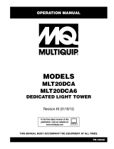
LAMP FOOTCANDLE PLOT
Figure 1. Lamp Footcandle Plot

LT6K5 50 HZ LIGHT TOWER • OPERATION MANUAL — REV. #0 (06/02/15) — PAGE 15
SPECIFICATIONS
Table 1. LT6K5 Specifications
Light Tower Model
LT6K5
Weight (Dry) 1,492 lbs. (671 kg.)
Support Points 4
Wind Stability 65 mph (80.46 kph)
Lights(4) 1,000-Watt Metal Halide
Lumens 440,000
Light Coverage 5 to 7 acres
Light Termination 4 x 3-pin QD plug
Winch Capacity (2) 1,500 lbs. (680 kg.)
Winch Rope Wire 3/16 in.
Generator Specifications
GFCI Receptacle Output 230 VAC @ 15 Amps
GFCI Circuit Breaker (CB4, Single Pole) 15 Amps
Main Breaker (CB1, 2-Pole) 30 Amps
Light Circuit Breakers (CB2/CB3 Single Pole) 20 Amps
Continuous Output 6,000 Watts
Noise Level @ 23 ft. (7 m) 68 dB
Trailer Specifications
Jackstand Capacity 2,000 lbs. (907 kg.)
Coupler Types
Fixed 2 in. Ball Coupler (Standard)
Adjustable 2 in. Ball Coupler (Option)
Fixed Pintle Eye-Ring Coupler (Option)
Adjustable Pintle Eye-Ring Coupler (Option)
Tire Size 13 in. (330 mm.)
Tire Rim Size 13 x 4.5 in. (330 x 114 mm)
Axle Capacity 2,000 lbs. (907 kg.)
Hub Type 5-Lug
Suspension Type 4-Leaf
Electrical Tail-Light Connector 4-Wire Flat

PAGE 16 — LT6K5 50 HZ LIGHT TOWER • OPERATION MANUAL — REV. #0 (06/02/15)
SPECIFICATIONS
Table 2. Engine Specifications
Kohler KDW 1003
Diesel Engine
TIER 4F
Engine Type 3-Cylinder, Diesel Engine
Displacement 62.73 cu. in. (1028 cc)
Max Output Standby 12 H.P. at 1,800 R.P.M.
Fuel Tank Capacity Approx. 34 U.S. Gallons (103.6 Liters)
Run Time With 4 Lights 64 Hours
Standard Idle Speed 1,800 R.P.M.
Fuel Type Low Sulfur No. 2 Diesel Fuel
Oil Sump Capacity 2.64 U.S. Quarts (2.5 Liters)
Cooling System Liquid-cooled
Coolant Capacity 1.25 U.S. Quarts (4.75 Liters)
Starting Method Electric Start
Battery Type Group 24
Total Weight (Dry) 187.3 lbs. (85 Kg.)

LT6K5 50 HZ LIGHT TOWER • OPERATION MANUAL — REV. #0 (06/02/15) — PAGE 17
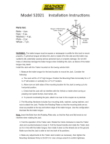
DIMENSIONS
Figure 2. Dimensions
Table 3. Dimensions
Reference Letter Description Dimension
A Length (Mast Stowed Position) 128.3 in. (326 cm.)
B Length (Hitch To Rear Ext. Outrigger) 106 in. (269 cm.)
C Max. Height (Mast Deployed Position) 31.5 ft. (960 cm)
D Height (Mast Stowed Position) 73.7 in. (187 cm.)
E Ground Clearance (From Axle) 18.6 in. (47.2 cm.)
F Width (Tow Ready) 42.4 in. (108 cm.)
G Width (Outriggers Deployed) 79 in. (201 cm.)
F
G
STOWED
POSITION
DEPLOYED
POSITION
A
B
E
C
D

PAGE 18 — LT6K5 50 HZ LIGHT TOWER • OPERATION MANUAL — REV. #0 (06/02/15)
GENERAL INFORMATION
The Multiquip LT6K5 Light Tower is a dedicated general
purpose light tower engineered to provide dependable
lighting for a wide range of applications. This includes
lighting for construction sites, industrial locations, special
events, and emergency conditions.
METAL HALIDE LAMPS
The lighting system of the LT6K5 is comprised of 4 metal
halide, 1000-watt lamps. These lights provide maximum
illumination with typical lighting coverage of 5 to 7 acres.
The lights are controlled by two 20 amp circuit breakers.
Each breaker will turn on a pair of lights (top/bottom).
ENGINE
The LT6K5 is powered by a Tier (4) Kohler, 3-cylinder, water
cooled, direct injection, 12 HP diesel engine that is equipped
with automatic shutdowns for low oil pressure, high coolant
temperature, and alternator charge failure.
STABILITY
The light tower mast has a maximum vertical height of 31.5
feet (9.6 meters) and can be raised by means of a manual
winch. The tower tensioning system is designed to provide
the necessary tension to safely control the pivot of the tower.
The light tower has a wind stability of up to 65 mph with
outriggers and jackstands fully deployed on level ground.
PANEL LIGHT
A panel light automatically illuminates the control panel
when the engine access door is opened (air filter side).
This feature is convenient for night deployment.
CONVENIENCE RECEPTACLE
The LT6K5 is equipped with a GFCI receptacle located on
the control panel. To gain access to this receptacle, lift the
side panel door on the air filter side of the generator.
The GFCI receptacle can supply 230 VAC at 15 amps.
This receptacle can be used for light power tools or other
similar applications.
FUEL TANK
The 34-gallon fuel tank provides up to 72.5 hours of run
time while running at 3/4 load.
TRAILER DESIGN
The trailer design of the LT6K5 light tower withstands the
rigors of normal highway towing and jobsite environments.
The trailer is engineered to DOT requirements and is in
compliance to the standards of the National Association
of Trailer Manufacturers (NATM).
BUNDED SYSTEM
The LT6K5 light tower is designed with a "bunded"
containment system. This system prevents the leakage,
spilling of harmful contaminants, fluids that could be harmful
to the environment.

LT6K5 50 HZ LIGHT TOWER • OPERATION MANUAL — REV. #0 (06/02/15) — PAGE 19
NOTES

PAGE 20 — LT6K5 50 HZ LIGHT TOWER • OPERATION MANUAL — REV. #0 (06/02/15)
COMPONENTS
Figure 3. Major Components 1 (Control Panel Side)
1
11
10
10
9
8
120/240 VAC ENGINE
HOURS
OFF OFF
OFF
OFF OFF
1/10
LIGHTING120 VAC
4
5
6
3
7
2
3
Figure 3, 4, and 5 show the location of the controls and
components for the LT6K5 light tower. The function of each
component is described below:
1. Ball Hitch Coupler — Attach the trailer's 2-inch coupler
to the towing vehicle. Use only the specified ball diameter
as indicated on your coupler. Use of any other ball
diameter will create an extremely dangerous condition
which can result in separation of the coupler and ball
or ball failure.
2. Tongue Jackstand — Use this jackstand to support the
tongue when attaching the light tower to a towing vehicle.
3. Side Marker Lights — There are four side marker lights
located on light tower. The front circular lights (tongue
side) are amber. The rear rectangular reflectors are red.
4. Manual Holder — Contains information regarding the
light tower.
5. Panel Light — When the cabinet door is raised, the
light will automatically turn on. When the cabinet door
is closed, the light will turn off.
6. Control Panel — Contains the auxiliary output
receptacle, engine hour meter, excitation capacitor and
circuit breakers.
7. T-Bar — Allows the lights to be mounted vertically or
horizontally.
8. Engine — 3-cylinder, water cooled, direct injection,
12 HP diesel engine.
9. Engine Status Module — Displays engine status via
LEDs, water temperature, air filter, fuel, alternator, oil
pressure, glow plugs. Insert ignition key, turn clockwise
to start engine.
10. Tie-Down Points — Used to tie down light tower with
straps or chains to allow even application of force to the
front and rear of the equipment during transport.
11. Chock Blocks — Place blocks (not included as part
of the light tower package) under each trailer wheel to
prevent rolling.
/