Page is loading ...

P/N 780101708 2/18 Rev Awww.fieldcontrols.com
This device MUST be installed by a qualified agency in accordance with the manufacturer’s installation instructions.The definition of a
qualified agency is: any individual, firm, corporation or company which either in person or through a representative is engaged in, and
is responsible for, the installation and operation of HVAC applicances, who is experienced in such work, familiar with all the precautions
required, and has complied with all the requirements of the authority having jurisdiction.
READ THESE INSTRUCTIONS CAREFULLY AND COMPLETELY BEFORE PROCEEDING WITH THE INSTALLATION.
Installed By:_______________________________________ Phone: _____________________ Installation Date: _____________
Please retain these instructions after installation.
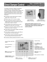
The EvenAir thermostat controls heating, cooling and AIRFLOW to the sleeping and living areas in a
home. The thermostat is installed in the downstairs living area, a wiring hub is installed at the
equipment, one or two wired or wireless temperature sensors are installed in the upstairs sleeping
area and modulating dampers are installed to control the airflow to the living and sleeping areas. The
wiring hub is connected to the thermostat using the existing thermostat wiring. The EvenAir thermostat
can also be used to control humidification and de-humidification, fresh air intake per ASHRAE 62.2,
ERVs or HRVs, whole house fans and economizers.
The EvenAir thermostat monitors the temperature at the sensor and the temperature at the thermostat
every 2 minutes during heating and cooling calls. If the temperatures are different, the EvenAir
thermostat automatically adjusts the modulating dampers 2% to allow additional airflow directed to
the area that needs it for a uniformly comfortable home.
COMPONENTS:
T32 Thermostat
H32 Wiring Hub (sold separately)
AMJ Type Dampers
1 TS51 or 2 TS52 Wired Sensors
(sold separately)
(sold separately)
T32
R
INSTALLATION AND USER MANUAL
THERMOSTAT WITH AIRFLOW CONTROL
For Wireless Temperature Sensors
1 or 2 TSER Wireless Sensors
1 ER1 Electronic Receiver Module
(sold separately)
(sold separately)
R
Model H32
PN 580011201
Wiring Hub
24VAC, 10VA
Made in USA
C NO O LT SR
F I E L D
R
Living
Tu
Day
Sleeping
Living
Airflow %
COOL
Schedule
AUTO
FANMENU MODE
Cool
Set To
SYSTEM
AM
R

Living
Tu
Day
Sleeping
Living
Airflow %
COOL
Schedule
AUTO
FANMENU MODE
Cool
Set To
SYSTEM
AM
UP/DOWN Keys
SYSTEM MODE Key
Displays the living area,
sleeping area or outdoor
temperatures or indoor RH%.
Displays the Thermostat Mode
HOLD, SCHEDULE or VACANT
Displays the time, day and
schedule. MORNING, DAYTIME,
EVENING or NIGHT
MENU Key
MODE Key
Displays the sleeping area airflow
Displays the heating or
cooling setpoint temperature
or the humidity (RH%) setpiont.
FAN MODE Key
Displays the living area airflow
NEXT Key
ENTER Key
SYSTEM MODES
Hold, Schedule or Vacant
Monitors and displays indoor relative humidity from10 to 80%.
Morning, Daytime, Evening and Night
Weekdays and weekend – 5/2
Temperature is held for 3 hours when adjusted in Schedule
mode.
FAN MODES
Airflow control can be turned off and the thermostat will operate
as a typical thermostat.
Maximum airflow limits can be set for heating and cooling
modes during installation.
NIGHTTIME OPERATION
Gas/electric equipment with 2-stage heating and 2-stage
cooling or conventional or dual fuel heat pumps with 2
compressor stages and 1 auxiliary heating stage.
Wired or wireless temperature sensors can be used in the
sleeping area. For wired sensors, use one TS51 sensor or two
TS52 temperature sensors. For wireless sensors, use one or two
TSER wireless sensors. Wireless sensors require the ER1
electronic receiver module to be installed in the wiring hub.
Round or rectangular dampers using the AMJ actuator and up
to 1 inch static pressure.
Controls a fresh air damper. Set minutes per hour of fresh air
operation. Set temperature limits for fresh air operation.
Controls a humidifier during heating using relay contacts.
Thermostat is powered by the wiring hub that operates on
24VAC from the HVAC equipment using the R and C wires.
FEATURES
The airflow to the living area or sleeping area can be adjusted.
After 3 hours, the thermostat returns to automatic airflow
control.
Displays User options.
Selects Thermostat Mode
HOLD, SCHEDULE or VACANT
OFF, HEAT, COOL, AUTO,
EHEAT or ECOOL
AUTO, ON or VENT
Used to save options and
return to thermostat operation
Used to advance through options
Off, Heat, Cool, Auto. EHeat or emergency heat is available
when heat pumps are used. ECool is available to control a
whole house fan or economizer when installed.
Auto, On (Continuous) or Vent
THERMOSTAT MODES
HUMIDITY
PROGRAMS PER DAY
PROGRAM FORMAT
TEMPERATURE OVERRIDE
AIRFLOW OVERRIDE
AIRFLOW CONTROL
AIRFLOW LIMITS
At night, the EvenAir thermostat uses the temperature sensor in
the sleeping area to control heating and cooling calls and
directs more airflow to the sleeping area.
COMPATIBLE EQUIPMENT
TEMPERATURE SENSOR
MODULATING DAMPERS
FRESH AIR CONTROL PER ASHRAE 62.2
HUMIDIFIER CONTROL
POWER
THERMOSTAT OVERVIEW
R
page 2 of 16
Thank you for purchasing the EvenAir System from Field Controls. The EvenAir products are compatible
with any HVAC system having accessible 24VAC terminals.
P/N 780101708 2/18 Rev A
Controls different whole house fan/economizer configurations
for eCooling using a timer or true temperature control.
WHOLE HOUSE FAN/ECONOMIZER CONTROL
Press the touchscreen with your fingertip only, using a firm touch. Do not use a sharp object such as a pen or pencil.
The touchscreen is a resistive touch and responds differently than touchscreens found in smart phones/devices.
!

HOMEOWNER
Overriding Automatic Airflow
Terminating Automatic Airflow
THERMOSTAT OPERATION AND USER SETTINGS
Set Time and Day
Set System Mode
Set Fan Mode
Temperature Override
Set Thermostat Mode
Changing Setpoint Temperatures or Humidity (RH%) setpoint
Displaying Living and Sleeping area temperature,
Outdoor temperature or indoor Humidity (RH%)
EvenAir Thermostat Operation
1
2
3
4
5
6
7
8
9
Changing Batteries
Set Schedule
Turn Automatic Airflow Control On/Off
Turn Nighttime Airflow Control On/Off
Clean the Touchscreen
Set Nighttime Airflow in Heating
Set Nighttime Airflow in Cooling
User Options
1
2
3
4
5
7
FEATURES
NIGHTTIME AIRFLOW CONTROL
uses the temperature sensor in the sleeping area to control heating and cooling calls and directs more airflow to the
sleeping at night and less airflow to the unoccupied living . Nighttime Airflow Control begins at 10:00pm but
can be changed by accessing the schedule in the User Options. The airflow to the sleeping area defaults to 130% but
can be adjusted for both heating and cooling in the User Options. Nighttime Airflow Control is defaulted to On but can
be turned Off in the User Options. The homeowner should consider turning this option off if bedrooms are located on
the same floor as the living area and using the same airflow trunk as the living area.
area area
AUTOMATIC OR MANUAL AIRFLOW CONTROL
by homeowners to maintain uniform comfort throughout the home. However, homeowners with unusual work schedules,
home offices, etc. may want to use the manual airflow control feature. This feature allows the homeowner to change the
airflow level as desired and hold that level indefinitely. This feature needs to be enabled using Installer Option 19. The
homeowner then needs to turn automatic airflow control OFF using the User Options. The Nighttime Airflow Control
option is still enabled but can be turned off, if desired, using the User Options.
AIRFLOW OVERRIDE
DISPLAYING THE LIVING AND SLEEPING AREA TEMPERATURE
Touch in this area to display the Sleeping area temperature, outdoor temperature (if outdoor temperature sensor
installed) or the indoor humidity (RH%).
more airflow may be desired in the living area. The homeowner sets the airflow level to the area and the thermostat will
hold the airflow for 3 hours. After 3 hours, the thermostat returns to automatic airflow control.
Features
AIRFLOW CONTROL TURNED OFF
only. The thermostat operates just like any other thermostat. The airflow control options are disabled and airflow is no
longer displayed on the thermostat.
EASY UPGRADE TO WIFI
and simply plugs into the same subbase and requires no additional wiring. Contact Field Controls technical support for
technical information and Field Controls customer support to purchase additional components.
HOMEOWNER SECTION
This manual is separated into two different sections: one for the Homeowner and one for the System Installer.
The Homeowner section contains information on features and operation of the thermostat along with
optional user settings available to the homeowner.
P/N 780101708 2/18 Rev A
page 3 of 16
Set eCool Timer
6
WHOLE HOUSE FAN / ECONOMIZER CONTROL
whole house fan or economizer, if installed, to bring in cool outdoor air, reducing energy costs and enhancing indoor
air quality. The thermostat controls eCooling either manually using a 1 to 12 hour timer set at the thermostat or by true
temperature control for total comfort and convenience. Check with your installer regarding your specific installation.
The Nighttime Airflow Control option is an energy saving feature where the thermostat
Automatic Airflow Control is the thermostat default and is typically used
The living area temperature is normally displayed.
On occasion, homeowners may want to direct more airflow to an area. For example, during a party,
In some installations, the EvenAir thermostat has been installed to control the system
The EvenAir thermostat includes an eCool feature that can control a
HUMIDITY or DE-HUMIDIFICATION CONTROL
humidifier, if installed, or de-humidification, if enabled. The thermostat can display the humidity and the humidity level
can be changed by the user for a more comfortable home during the heating and cooling season.
The EvenAir thermostat includes a humidity sensor that can control a
The EvenAir WiFi thermostat provides remote access to your home’s heating and cooling system

THERMOSTAT OPERATION
HOMEOWNER SECTION
Set Time and Day
ENTER
AM
Touch the
UP/DOWN keys to
change the HOUR.
Touch NEXT.
CHANGE THE HOUR
Touch the
UP/DOWN keys to
change the MINUTE.
Touch NEXT.
CHANGE THE MINUTE
Touch the
UP/DOWN keys to
change the DAY OF
THE WEEK.
Touch ENTER.
CHANGE THE DAY OF THE WEEK
Day
Airflow %
COOL
Schedule
AUTO
FANMENU MODE
Cool
Set To
SYSTEM
Touch here to change the time and day of the
week.
We
AM
ENTER
AM
Tu
AM
NEXT
NEXT
ENTER
Living
Sleeping
Living
1
Depending on the mode, setting the time
may reset the setpoint temperature to the
factory default heating or cooling setpoint.
i
Living
Schedule
AUTO
Set To
FAN
SYSTEM
Heat
OFF
Tu
Day
Living
MENU MODE
AM
Sleeping
Airflow %
Living
Tu
Day
Living
Schedule
AUTO
MENU MODE
Set To
AM
Sleeping
Airflow %
FAN
SYSTEM
Heat
HEAT
Living
Schedule
AUTO
Set To
FAN
SYSTEM
Cool
COOL
Tu
Day
Living
MENU MODE
AM
Sleeping
Airflow %
Living
Living
Living
Tu
Tu
Tu
Day
Day
Day
Living
Living
Living
Schedule
Schedule
Schedule
AUTO
AUTO
AUTO
Set To
Set To
Set To
AM
AM
AM
Sleeping
Sleeping
Sleeping
Airflow %
Airflow %
Airflow %
SYSTEM
SYSTEM
SYSTEM
Heat
Heat
Cool
AUTO
EHEAT
COOL
E
MENU
MENU
MENU
MODE
MODE
MODE
FAN
FAN
FAN
Heating and cooling
systems are off.
OFF
HEAT
Only heating calls are
enabled and heating
setpoint is displayed.
“HEAT” will blink in
an active heating call.
Only cooling calls are
enabled and cooling
setpoint is displayed.
“COOL” will blink in
an active cooling call.
COOL
AUTO
EHEAT
ECOOL
Heating or Cooling
calls are enabled.
“HEAT” will blink in
an active heating call
or “COOL” will blink
in an active cooling
call.
Emergency Heating
for heat pumps.
“EHEAT” will blink in
an active heating call.
Only displayed if heat
pump equipment.
Econo Cooling brings
in cooler outdoor air
when a whole house
fan or economizer is
installed. “ECOOL”
will blink in an active
call.
Set System Mode
2
Touch the SYSTEM key to display the SYSTEM
MODES: OFF, HEAT, COOL, AUTO, EHEAT or
ECOOL. In AUTO or OFF, the setpoint for the last
system call is displayed.
Set Fan Mode
Touch the key to change the FAN MODES -
AUTO, ON or VENT.
FAN
Tu
Day
Airflow %
COOL
Schedule
MENU MODE
Cool
Set To
AM
AUTO
ON
Fan is activated only
during heating or
cooling calls. This is
the most commonly
used setting.
Fan is continuously
on.
SYSTEM
Living
Living
Sleeping
FAN
3
AUTO
Tu
Day
Airflow %
COOL
Schedule
MENU MODE
Cool
Set To
AM
SYSTEM
Living
Living
Sleeping
FAN
ON
Set Thermostat Mode
4
Touch the key to display the THERMOSTAT
MODES: HOLD, VACANT and SCHEDULE.
MODE
Tu
Day
Airflow %
COOL
AUTO
FANMENU
Cool
Set To
SYSTEM
AM
SCHEDULE MODE
HOLD MODE
VACANT MODE
Setpoint temperatures
are changed at
scheduled times
defined by the user.
Setpoint temperatures
are set by the user.
No schedule is used.
Setpoint temperatures
are kept at the vacant
temperatures set by
the installer.
MODE
Living
Living
Sleeping
Tu
Day
Airflow %
COOL
AUTO
FANMENU
Cool
Set To
SYSTEM
AM
MODE
Living
Living
Sleeping
Tu
Day
Airflow %
COOL
AUTO
FANMENU
Cool
Set To
SYSTEM
AM
Schedule
MODE
Living
Living
Sleeping
Hold
Vacant
Changing the Setpoint Temperature
or RH% Setpoint
The UP/DOWN keys are used to change the
setpoint temperature.
Tu
Day
Airflow %
Schedule
MENU MODE
AM
Living
Living
Sleeping
5
COOL
AUTO
FAN
SYSTEM
Touch the UP or DOWN key to raise or lower the
Cooling setpoint, Heating setpoint or Humidity
setpoint.
The thermostat will return to displaying the active
setpoint temperature after about 30 seconds.
To override the Schedule setpoint temperature:
Living
Tu
Day
Sleeping
Living
Airflow %
COOL
Schedule
AUTO
FANMENU MODE
Cool
Set To
SYSTEM
AM
Touch the UP/DOWN
keys to adjust the
setpoint temperature.
The thermostat displays the temperature in the
downstairs living area and is indicated by Living.
The thermostat also displays the Sleeping area
temperature, the Outdoor temperature (if sensor is
installed) and the humidity in the living area.
Displaying the Living, Sleeping or
Outdoor Temperature or Indoor RH%
MENU
Airflow %
We
Day
AUTO
FANMODE
Cool
Set To
SYSTEM
AM
Living area temperature
is displayed.
Temperature Override
Schedule
Sleeping
COOL
Sleeping
Living
MENU
Airflow %
We
Day
AUTO
FANMODE
Cool
Set To
SYSTEM
AM
Schedule
Living
COOL
Sleeping
Living
6
7
The Sleeping area
temperature is displayed.
Press the area again
to display the Outdoor
temperature.
After 3 hours, the
thermostat returns to
the Schedule
temperature.
VENT
The fan will be
activated for 15
minutes if no cooling
or heating calls have
occurred in the last
120 minutes.
Tu
Day
Airflow %
COOL
Schedule
MENU MODE
Cool
Set To
AM
SYSTEM
Living
Living
Sleeping
FAN
VENT
Set System Mode (Continued)
2
P/N 780101708 2/18 Rev A
page 4 of 16
VENT mode must be enabled in the installer options.
ECOOL will only be displayed if a whole
house fan or economizer has been installed.
i
i
Some installations require a window to be
open before operating in the ECOOL mode.
Check with your installer.
Set To
Cool
Touch here to display
the Cooling setpoint,
Heating setpoint and
the Humidity setpoint
(only displayed if
Humidity options
have been set by the
installer).
The Outdoor temperature
is displayed. Press the
area again to display
the Humidity (RH%).
The outdoor temp will only be displayed if an
outdoor temperature sensor is installed.
MENU
Airflow %
We
Day
AUTO
FANMODE
Cool
Set To
SYSTEM
AM
Schedule
Outdoor
COOL
Sleeping
Living
The indoor Humidity
(RH%) is displayed.
Press again to display
the Living area
temperature.
MENU
Airflow %
We
Day
AUTO
FANMODE
Cool
Set To
SYSTEM
AM
Schedule
RH%
COOL
Sleeping
Living
Press this area to
display the upstairs
Sleeping area
temperature.

HOMEOWNER SECTION
THERMOSTAT OPERATION (Continued)
Overriding Automatic Airflow
Touch the Airflow %
area to override
AUTOMATIC
AIRFLOW to the
living area or the
upstairs sleeping
area.
Touch the UP key to
increase the airflow
to the sleeping area
or touch the DOWN
key to increase
airflow to the living
area.
Airflow % will blink to indicate airflow override.
After 3 hours, the thermostat returns to automatic
operation. The override range is defined by the
installer during set up.
8
COOL
AUTO
FANMENU
Cool
Set To
SYSTEM
PM
MODE
Living
Hold
We
Eve
COOL
Hold
AUTO
FANMENU MODE
SYSTEM
PM
Airflow %
Living
Sleeping
Living
Airflow %
Sleeping
Living
Eve
We
Terminating Airflow Override
To terminate Airflow
Override, touch the
AIRFLOW% area.
9
COOL
AUTO
FANMENU
Cool
Set To
SYSTEM
PM
MODE
Living
Hold
We
Eve
COOL
Hold
AUTO
FANMENU
SYSTEM
PM
Airflow %
Living
Sleeping
Living
Airflow %
Sleeping
Living
Eve
We
MODE
Then touch the
MODE key.
The thermostat returns to automatic airflow
control. The AIRFLOW % returns to the airflow
prior to the override.
USER OPTIONS
Change Factory Set Schedule
Touch the
key to display
SCHEDULE. If no
key is touched, the
thermostat returns to
normal operation
after about 30
seconds.
MENU
1
Day
Airflow %
COOL
Schedule
AUTO
FANMODE
Cool
Set To
SYSTEM
Tu
AM
Living
Sleeping
Living
MENU
Factory Set Schedule
Morn
Day
Even
Nite
Monday - Friday
The thermostat comes pre-set with the
following energy-saving schedule for
weekdays (Mon-Fri) and weekends (Sat-Sun).
Using these settings can reduce your heating
and cooling expenses.
6:00 AM
8:00 AM
6:00 PM
10:00 PM
70
62
70
62
Time Heat Cool
Morn
Day
Even
Nite
Saturday & Sunday
6:00 AM
8:00 AM
6:00 PM
10:00 PM
70
62
70
62
75
75
83
83
75
75
78
78
Time Heat Cool
WeTuMo ThFr
Schedule
Touch the UP key to
select the weekday
schedule
(MoTuWeThFr) or
touch the DOWN
key to select the
weekend schedule
(SaSu). Touch NEXT.
SELECTING THE WEEKDAY OR
WEEKEND SCHEDULE
WeTuMo
Morn
ThFr
Schedule
MENU NEXT ENTER
AM
WeTuMo
Morn
ThFr
Schedule
Heat
Set To
AM
Touch the
UP/DOWN keys to
change the Morning
Start Time. Touch
NEXT.
SETTING THE MORNING
SCHEDULE START TIME.
Touch the
UP/DOWN keys to
change the Morning
Heating Setpoint.
Touch NEXT.
SETTING THE MORNING
HEATING TEMPERATURE.
MENU NEXT ENTER
MENU NEXT ENTER
SETTING THE MORNING
COOLING TEMPERATURE.
WeTuMo
Morn
ThFr
Schedule
MENU
Cool
Set To
AM
Touch the
UP/DOWN keys to
change Morning
Cooling Setpoint.
Touch NEXT.
Continue setting the start times, heating setpoints,
cooling setpoints for the Day, Evening and Night
schedules.
NEXT ENTER
Touch ENTER to save the schedule.
Factory Set Schedule (Continued)
Automatic Airflow Control On or Off
Thermostat defaults
to Automatic Airflow
Control On and
automatically directs
more airflow to where
it’s needed.
Airflow %
NEXT
To turn Automatic
Airflow Control OFF,
touch the DOWN
key. The user must
set the airflow when
airflow control is off.
MENU
2
i
This option is only displayed if User Airflow
Control has been turned On by the installer in
the Installer Options.
ENTER
Touch the key to save and go to next
option or touch the ENTER key to save the options
and return to normal thermostat operation.
MENU
Homeowners with an unusual schedule, home
office, etc. may want to use this option.
With Automatic Airflow Control Off, the
Nighttime Airflow Control option is still
enabled. If desired, the homeowner can turn
the Nighttime Airflow Control option off using
User Options.
i
i
Airflow %
NEXTMENU ENTER
Touch the MENU key until the following
thermostat screen is displayed.
P/N 780101708 2/18 Rev A
page 5 of 16

HOMEOWNER SECTION
USER OPTIONS (Continued)
Nighttime Airflow Control On or Off
NIGHTTIME AIRFLOW CONTROL defaults to On
and is used to save energy. The thermostat uses
the temperature sensor in the sleeping area for
controlling heating and cooling calls. The airflow
is increased to 130% to the sleeping area and the
airflow is reduced to 70% to the unused living
area. The thermostat displays the sleeping area
temperature.
Night
Upstairs
Airflow %
MENU NEXT ENTER
3
This option is not displayed if Airflow Control
has been turned off by the installer using the
Installer Options.
If bedrooms are located downstairs, consider
turning the Nighttime Airflow Control OFF.
i
i
Touch the MENU key to save and go to next
option or touch the ENTER key to save the options.
Night
Upstairs
Airflow %
MENU NEXT ENTER
Touch the MENU key
to display
NIGHTTIME
AIRFLOW indicated
by nAF On or Off.
Touch the UP key to
turn the option ON.
Touch the DOWN
key to turn the
option OFF.
Default start time for Nighttime Airflow is
10:00pm but can be changed using User
Option 1 to change the Night Schedule Start
Time.
Default airflow level upstairs is 130%. If a
different airflow level is desired, use User
Option 4 to change the airflow level in heating
and User Option 5 to change the airflow level
in cooling.
i
i
Set the Nighttime Airflow in Heating
This option is used to change the default
nighttime airflow in heating of 130% to a user
desired airflow level, not to exceed installer limits.
Night
Sleeping
Airflow %
Heat
Touch the key to display NIGHTTIME,
UPSTAIRS AIRFLOW IN HEATING indicated by
nAF Heat.
Use the UP/DOWN keys to adjust the airflow.
Touch the MENU key to save and go to next
option or touch the ENTER key to save the option.
MENU
Set the Nighttime Airflow in Cooling
This option is used to change the default
nighttime airflow in cooling of 130% to a user
desired airflow level, not to exceed installer limits.
Night
Sleeping
Airflow %
Cool
Touch the MENU key to display NIGHTTIME,
UPSTAIRS AIRFLOW IN COOLING indicated by
nAF Cool.
Use the UP/DOWN keys to adjust the airflow.
Touch the MENU key to save and go to next
option or touch the ENTER key to save the option.
MENU ENTER
NEXT
MENU ENTER
NEXT
5
4
This option is not displayed if Airflow Control
has been turned off.
This option is not displayed if Airflow Control
has been turned off.
i
i
Monday through Friday
6:00 AM
8:00 AM
6:00 PM
10:00 PM
70
62
70
62
Time Heat Cool
Saturday and Sunday
6:00 AM
8:00 AM
6:00 PM
10:00 PM
70
62
70
62
75
75
83
83
75
75
78
78
Time Heat Cool
Morn
Morn
Even
Even
Day
Nite
Day
Nite
Time Heat Cool
01
Factory Set Schedule
Schedule
Default Settings
Record User Selection if Changed
from Default Setting
Record User Selection if Changed
from Default Setting
Display Range Default
Automatic Airflow Control (requires Installer Option 18
enabled or will not show up as a User Option
Nighttime Airflow Control
Set the Nighttime Airflow in Heating (will only show if
Nighttime Airflow Control is ON)
Set the Nighttime Airflow in Cooling (will only show if
Nighttime Airflow Control is ON)
Clean the Touch Screen (in seconds)
02
03
04
05
06
A Ac
n AF
nAF + Heat
nAF + Cool
CL
On or Off
On or Off
%
%
N/A
On
On
130%
130%
30
N/A
NA
User Options (Homeowner)
Time
Heat
Cool
Clean the Touch Screen
This option disables the touch screen for 30
seconds to enable the user to clean the touch
screen by wiping down with a soft, damp cloth.
Touch the MENU key
to display CLEAN
DISPLAY option
indicated by CL. To
exit this option, press
NEXT.
NEXT ENTERMENU
7
OFF
Press ENTER to start
the 30 second count
down. The touch
screen is disabled
during this time.
INSTALL / REPLACE AA BATTERIES
Two AA batteries power
the clock when 24VAC
power is lost. Slide the
battery cover downward
and install the two AA
batteries, paying
attention to the polarity.
- + - +
P/N 780101708 2/18 Rev A
page 6 of 16
Set eCool Timer
Use this option to set the number of hours (1 -12)
you would like eCool to run before turning Off.
Touch the MENU key to save and go to next
option or touch the ENTER key to save the option.
6
This option is only displayed if a whole house
fan or economizer is installed and controlled
using the timer in the thermostat.
i
Touch the MENU key
to display eCOOL
TIMER option
indicated by ETc.
Touch the
UP/DOWN keys to
set the hours.
MENU ENTER
NEXT
COOL
E

CAUTIONS
Use cautions when mounting components to surfaces
that may have concealed wiring beneath the surface.
!
INSTALLATION
Before installing the EvenAir comfort system, turn off
all power to your HVAC system.
Read and follow all instructions carefully.
Follow all local electrical codes during installation. All
wiring must conform to local and national electrical
codes.
i
ATTENTION INSTALLER
Nighttime Airflow Control is defaulted to ON. If
bedrooms are located downstairs, consider turning this
option Off using the User Options if bedrooms are not
on the same trunk.
Fresh Air Control is defaulted to Off and controlled by
Options 20 thru 25.
Whole House Fan or Economizer Control is defaulted
to Off and controlled by Options 30 thru 34.
Humidifier and De-Humidification Control is defaulted
to Off and controlled by Options 40 thru 42.
Airflow Control is defaulted to On and controlled by
Options 50 thru 57.
Install and wire components to the wiring hub. (See
H32 Wiring Hub manual for wiring detail)
Airflow Control Off Option 50 turns off Airflow Control.
The thermostat controls the system, dampers fully open,
nighttime airflow control is disabled and airflow is no
longer displayed on the thermostat.
User Airflow Control can be enabled using Option 52
User turns off automatic airflow control in the User
Options.
INSTALLER SECTION
This manual is separated into two different sections: one for the Homeowner and one for the System Installer.
The Installer section contains setup and installation information of the thermostat with optional user
settings available for the homeowner.
Read entire manual before installing EvenAir products.
When servicing EvenAir system or accessing products,
turn off all power to these items.
Place the thermostat on the subbase. Do not install
batteries.
Turn power to the HVAC equipment On.
Check for Start Up Messages/Errors.
Set equipment options 1-6 if different than factory
default settings. (see Installer Options section).
1)
3)
If wireless sensors are used, install the ER1 electronic
receiver module in the wiring hub and set the sensor
number and home number as necessary.
(see H32 Wiring Hub manual).
2)
4)
5)
6)
Test the installation by initiating a heating call, cooling
call and fan call.
7)
Install batteries and set the time and day (see Installing
Batteries and Set Time and Day section)
8)
REMOVE SUBBASE
Place a slotted screwdriver in the
slots as shown and rotate to
remove subbase from the
thermostat housing.
ATTACH SUBBASE TO WALL
Attach the subbase to an interior wall and about 5-feet above
the floor as shown using the screws and wall anchors supplied.
The wires to the wiring
hub pass through the
opening.
5V
GND
SA
WIRING HUB
SB
T32
i
Homes with plaster walls with steel lathe may
experience wireless communication interference
when using wireless sensors. Wired sensors are
recommended.
P/N 780101708 2/18 Rev A
page 7 of 16

INSTALLER SECTION
Startup Messages:
!
When the H32 Wiring Hub and Thermostat are powered, nC
will appear in the LCD display to indicate the thermostat has
not established communication with the Hub. After a few
seconds the message disappears indicating the thermostat and
wiring hub are now communicating.
Living
Living
We
We
Sleeping
Sleeping
Living
Living
Airflow %
Airflow %
HEAT
HEAT
Hold
Hold
AUTO
AUTO
FAN
FAN
MENU
MENU
MODE
MODE
Heat
Heat
Set To
Set To
SYSTEM
SYSTEM
AM
AM
Thermostat to Wiring Hub
Use 5-conductor (1 spare), 18 or 20 gage, thermostat cable to
wire the T32 thermostat to an H32 wiring hub.
T32
Terminal
5V
GND
SA
SB
Wire Color
Red
White
Blue
Yellow
Wiring Hub
Terminal
5V
GND
SA
SB
Function
24VAC Power
Common
Signal A
Signal B
WIRING
See H32 Wiring Hub Installation Manual (Document
p/n: 780101720) for detailed wiring instructions.
i
The T32 thermostat is connected to the wiring hub using the
existing thermostat cable in the home and eliminates having to
install any new wires within the living area of the home when
wireless sensors are used.
After wiring all components, place the thermostat on
the subbase. Do not install batteries. Turn power to the
HVAC equipment On and check for startup messages.
Set Installer Options and then test the installation using
the Installer Test Menu.
Warning!
!
Turn the power to the HVAC equipment off before wiring.
When the wiring hub and
thermostat are powered, a
blank LCD indicates that there
is no power to the thermostat.
Check the power indicator on
the wiring hub. If the power
indicator is on , turn off the
Living
Tu
Day
Sleeping
Living
Airflow %
COOL
Schedule
AUTO
FANMENU MODE
Cool
Set To
SYSTEM
AM
When the wiring hub and
thermostat are powered, nS is
displayed when the thermostat
has not detected a wired or
wireless sensor. For wired
sensors, turn off the power and
check the wiring between the
sensor and wiring hub and ensure the wires are secured in the
correct terminals. For wireless sensors, ensure that batteries are
installed in the wireless sensor and that the wireless sensor is
set to the correct number.
The wireless sensor sends a signal to the thermostat when a
temperature change has occurred or every 15 minutes. The
thermostat will clear the nS message once the thermostat
detects the sensor.
To check the wireless sensor
communication, place your finger over the thermistor on the
right side of the sensor to increase the temperature detected.
power and check the wiring from the thermostat to the wiring
hub for errors. If the power indicator is off, turn off the power
and check the wiring from the wiring hub to the system for
errors.
!
P/N 780101708 2/18 Rev A
page 8 of 16
+5V
GND
SB
WIRING HUB
SA
Existing thermostat cable
in replacement installations.
T32
Thermostat Model T32
P/N 750106511
R
C
W1B
O
Y1
G
W2E
Y2
DS
HFR
HVAC
SENSORS
HFR
ODT
ODT
SLP
SLP
GND
+5V
SA
SB
TSTAT
OPN
COM
24V
WH FAN
DAMPER
OPN
COM
24V
FR AIR
DAMPER
ERV/HRV
ERV/HRV
SPACE
LIVING
SPACE
SLEEP
Wiring Hub H32

INSTALLER OPTIONS
These set up features should only be accessed by a qualified installer during initial EvenAir thermostat
installation set up. The homeowner would not normally access these product set up features.
INSTALLER SECTION
P/N 780101708 2/18 Rev A
page 9 of 16
Option
01
02
03
04
07
08
09
10
11
13
14
06
05
15
16
17
20
21
22
23
24
25
30
31
32
34
40
41
42
33
50
51
52
53
12
54
55
56
57
60
58
59
Description
Equipment Type
Heat Pump Type
OBP Outdoor Balance Point
Compressor Stages
Compressor Minimum Off Time (minutes).
Gas Heating Minimum Off Time (minutes).
Minimum Run Time (minutes).
On-Off Temperature Differential
Smart Recovery.
Vacant Heating Setpoint.
Vacant Cooling Setpoint.
Calibrate Living Area Sensor
Fan Operation.
Heating Stages
Night Level LCD Backlight
Fresh Air Control per ASHRAE 62.2
Minutes of Fresh Air per Hour
Inhibit Fresh Air Using Temperature Limits
Fresh Air High Temperature Limit
Fresh Air Low Temperature Limit
Enable Indoor Fan VENT Mode
Whole House Fan Control
Economizer using Dampers and Equipment Fan
Economizer or WHFan controlled by temperature
Economizer or WHFan controlled by Timer
Humidifier Control
Automatic Adjustment of Humidity Setpoint
De-Humidification Control
Economizer or WHFan OD temperature differential
Airflow Control
Enable User Airflow Control
Upstaging Time
Maximum Airflow in Heating to the Sleeping Area.
Maximum Airflow in Heating to the Living Area.
Maximum Airflow in Cooling to the Sleeping Area.
Maximum Airflow in Cooling to the Living Area.
Maximum Temperature Difference Between
Sleeping and Living area.
Airflow Update Time
Calibrate Sleeping Area Sensor.
Factory Restore
Home Number
Thermostat Location
o o
0 Cooling On 1 above setpoint, Off at setpoint. Heating On1 below setpoint, Off at setpoint.
o o o o
1 Cooling On 1 above setpoint, Off .5 below setpoint. Heating On1 below setpoint, Off .5 above setpoint.
o o o o
2 Cooling On 1 above setpoint, Off 1 below setpoint. Heating On1 below setpoint, Off 1 above setpoint.
(GE Only)
(HP Only )
(Dual fuel HP Only )
Display
HPt
OBP
CPr
COt
HOt
O O d
S r
V A C
V A C
r n t
C A L
FAn
HtG
BL
FAC
FAt
FAL
FtH
FtL
FCt
HFn
EFn
EtL
Etr
HFc
HFA
dHF
EOd
AFC
UAC
USt
HAF+Heat
HAF+Heat
CAF+Cool
CAF+Cool
diF
AFt
C A L
Fr
Home
tLo
+ Night
+ Heat
+ Cool
Range
GE or HP
Co(conv) or dF (dual fuel)
35 to 55F
0, 1 or 2
0 to 9
0 to 9
0, 1 or 2
0n(Up) or Off(Down)
44 to 75F
74 to 95F
65 to 100F
0 to 65F
0 to 10F
0 to 9
+/- 5F
GA(Down) or EL(Up)
0, 1 or 2
On(Up) or Off(Down)
On(Up) or Off(Down)
On(Up) or Off(Down)
On(Up) or Off(Down)
On(Up) or Off(Down)
On(Up) or Off(Down)
On(Up) or Off(Down)
On(Up) or Off(Down)
On(Up) or Off(Down)
On(Up) or Off(Down)
On(Up) or Off(Down)
0 to 60 minutes
On(Up) or Off(Down)
On(Up) or Off(Down)
100 to 160%
5 to 30 minutes
100 to 160%
100 to 160%
100 to 160%
0 to 10F
1 to 20 minutes
+/- 5F
No or Yes
1 to 8
dS or uS
Default As Installed
GE
Co
40F
1
2
0
1
Off
65F
80F
95F
35F
0F
2
na
GA
1
On
Off
Off
Off
Off
Off
Off
Off
Off
Off
Off
30
On
Off
10
150%
150%
140%
140%
2F
1
dS
No
2
na

ACCESSING INSTALLER OPTIONS
!
Press the touchscreen with your fingertip
only, using a firm touch. Do not use a sharp
object such as a pen or pencil.
!
The NEXT key is used to display the next
option.
!
The ENTER key is used to save options and
return to normal thermostat operation.
!
The hidden BACK key is used to return to
previous options and is located to the left of
the NEXT key.
To access the Installer Options, and
the hidden Enter key for 7 seconds until
the first Option appears on the screen.
TOUCH
HOLD
Living
Tu
Day
Sleeping
Living
Airflow %
COOL
Schedule
AUTO
FANMENU
Cool
Set To
SYSTEM
AM
TOUCH HOLD and this key
for 7 seconds to access the
Installer Options.
The hidden BACK
key can be used to
return to previous
options.
MODE
INSTALLER SECTION
(Only displayed if Heat Pump and Dual
Fuel selected.)
P/N 780101708 2/18 Rev A
page 10 of 16
Requires TS3 Outdoor Temperature Sensor
to be installed. (see wiring hub, H32,
installer manual)
Use the UP/DOWN
keys to select
01 Equipment Type
This option is used to
select gas/electric or
heat pump
equipment.
Use the UP/DOWN
Select a
conventional (Co)
HP or a dual fuel
(dF) HP with fossil
fuel auxiliary heat.
Factory Default: GE. Range: GE or HP
02 Heat Pump Type
Factory Default: Co. Range: Co or dF
(Only displayed if Heat Pump equipment)
Option
Option
Factory Default: 40F. Range: 35F to 55F
Use the UP/DOWN
keys to select the
outdoor temperature
for switching to fossil
fuel heating in a dual
fuel heat pump.
Touch NEXT or ENTER.
NEXT ENTER
Option
03 Outdoor Balance Point
Use the UP/DOWN
keys to change the
minimum off time
(minutes) before
restarting the
compressor.
Touch NEXT or ENTER.
Option
Option
Use the UP/DOWN
keys to change the
minimum run time
(minutes) before
turning a system off.
Touch NEXT or ENTER.
Option
Use the UP/DOWN
keys to change the
minimum off time
(minutes) before
restarting a gas
furnace or electric
strip heater.
Touch NEXT or ENTER.
07 Compressor Minimum Off Time
Factory Default: 2 Minutes. Range: 0 to 9 Minutes
08 Gas Heating Minimum Off Time
Factory Default: 0 Minutes. Range: 0 to 9 Minutes
09 Minimum Run Time
Option
Option
Use the UP/DOWN
keys to set 0, 1 or 2
stage for a GE system
or 0 or 1 stage for HP
auxiliary heating
stages.
Touch NEXT or ENTER.
Use the UP/DOWN
keys to set 0, 1 or 2
stages.
Touch NEXT or ENTER.
Factory Default: 1 Stage. Range: 0,1 or 2
Factory Default: 1 Stage. Range: 0,1 or 2
Option
Use the UP key to
select “EL” for electric
operation where the
thermostat activates
the indoor fan (G
terminal) during
06 Fan Operation
Factory Default: Gas. Range: GA or EL
(Only displayed if Gas/Electric equipment.)
Touch NEXT or ENTER.
05 Heating Stages
04 Compressor Stages
NEXT
NEXT
ENTER
ENTER
NEXT ENTER
NEXT ENTER
NEXT ENTER
NEXT ENTER
Factory Default: 2 Minutes. Range: 0 to 9 Minutes
Use the UP key to
select ON to turn on
smart recovery or the
DOWN key to select
OF to turn smart
recovery off.
Touch NEXT or ENTER.
Smart recovery initiates a heating or cooling call
so that the space is at temperature when the
setback period ends.
Use the UP/DOWN
keys to select the
heating temperature
when the space is
vacant.
Touch NEXT or ENTER.
13 Vacant Heating Setpoint
11 Smart Recovery
Factory Default: Off. Range: On or Off.
Option
Option
Factory Default: 65F. Range: 44F to 75F
NEXT
NEXT
Vacant
Heat
ENTER
ENTER
Use the UP/DOWN
keys to select 0, 1, 2.
Touch NEXT or ENTER.
Option
Mode0
Mode1
Mode2
o
1.0 On/Off Span.
o
1.5 On/Off Span.
o
2.0 On/Off Span.
10 On-Off Temperature Differential
Factory Default: #1. Range: 0, 1 or 2.
NEXT ENTER
Use the
keys to set the time at
which second stage
heating or cooling is
activated.
Touch or
UP/DOWN
NEXT ENTER.
Option
12 Upstaging Time
Factory Default: 10 minutes. Range: 5 to 30 minutes
NEXT ENTER
gas/electric (GE) or heat pump (HP).
Touch NEXT or ENTER.
keys to select Co or dF type HP.
Touch NEXT or ENTER.
heating calls or DOWN key to select GA for gas
operation where the equipment plenum sensor
activates the indoor fan in heating calls.
If GE equipment is selected, this option determines
the number of heating stages - 0, 1 or 2 stages. If
HP equipment is selected, this option determines
the number of auxiliary heating stages - 1 or 1.
NEXT ENTER
NEXT ENTER

INSTALLER SECTION
P/N 780101708 2/18 Rev A
page 11 of 16
Use the
keys to select the
cooling temperature
when the space is
vacant.
Touch or
UP/DOWN
NEXT ENTER.
Use the UP/DOWN
keys to change the
Living area
temperature to the
temperature that the
user feels is correct.
Touch NEXT or ENTER.
14 Vacant Cooling Setpoint
Factory Default: 80F. Range: 74F to 95F
15 Calibrate Living Area
Temperature Sensor
o
Factory Default: None. Range - +/-5
Option
Option
NEXT
NEXT
Vacant
Cool
ENTER
ENTER
Living
Use the UP/DOWN
keys to change the
Sleeping area
temperature to the
temperature that the
user feels is correct.
Touch NEXT or ENTER
16 Calibrate Sleeping Area
Temperature Sensor
Factory Default: None.
Option
NEXT
o
Range - +/-5
Sleeping
ENTER
Option
Night
the low level backlight ON or touch the
key to turn OFF.
Touch or
DOWN
NEXT ENTER.
Use the key to
select ON or touch the
key to select
OFF.
Touch or
UP
DOWN
NEXT ENTER.
Use the key to
select ON or touch the
key to select
OFF.
Touch or
UP
DOWN
NEXT ENTER.
Use the key to
increase the fresh air
minutes or the DOWN
key to decrease the
minutes.
UP
The LCD has a low
level backlight that
can be used as a
night light.
Use the UP key to turn
Select ON to enable Fresh Air Control. Fresh air
damper opens and an optional ERV or HRV is
activated.
Select ON to inhibit fresh air control using outdoor
temperature limits set in options 23 and 24.
Select the number of minutes the fresh air
damper should open each hour based on
ASHRAE 62.2 calculations and damper size.
17 Night Level LCD Backlight
20 Fresh Air Control
per ASHRAE 62.2
22 Inhibit Fresh Air Using
Temperature Limits
21 Minutes of Fresh Air per Hour
Factory Default: On. Range: On or Off.
Factory Default: OFF. Range: On or Off.
Factory Default: OFF. Range: On or Off.
Factory Default: 30 minutes. Range: 0 to 60.
NEXT ENTER
Option
Option
Option
Select the maximum outdoor temperature for
fresh air damper operation.
Select the minimum outdoor temperature for
fresh air damper operation.
23 High Temperature Limit
24 Low Temperature Limit
Factory Default: 95F. Range: 65F to 100F.
Factory Default: 35F. Range: 0F to 65F.
Option
Option
NEXT ENTER
Use the key to
select ON or touch the
key to select
OFF.
UP
DOWN
Use the key to
select ON or touch the
DOWN key to select
OFF.
Touch NEXT or ENTER.
UP
Use the key to
select ON or touch the
key to select
OFF.
Touch or
UP
DOWN
NEXT ENTER.
Select ON to enable Fan VENT mode. In VENT
mode the indoor fan turns on to circulate air if a
heating or cooling call has not occurred in 120
minutes.
Select ON if a whole house fan is controlled by
the thermostat.
Select if dampers and the equipment fan is used
to bring in cool outdoor air for cooling. See the
Wiring Hub Installation for different economizer
configurations.
25 Enable Fan VENT Mode
30 Whole House Fan Control
31 Economizer Control
Factory Default: OFF. Range: On or Off.
Factory Default: OFF. Range: On or Off.
Factory Default: OFF. Range: On or Off.
Option
Option
Option
Use the
OWN key to change
the temperature
differential.
Touch or
UP and
D
NEXT ENTER.
Use the key to
select ON or touch the
key to select
OFF.
Touch or
UP
DOWN
NEXT ENTER.
Select ON to control the Whole House Fan or
Economizer using the outdoor, room and cooling
setpoint temperatures. See Option 34 to control
using a timer
Select the number of degrees the outdoor
temperature must be below the room
temperature to activate the Economizer or Whole
House Fan.
32 Economizer/Whole House Fan
Control by Temperature
33 Economizer or Whole House Fan
Outdoor Temperature Differential
Factory Default: OFF. Range: On or Off.
Factory Default: 0. Range: 0-10 degrees.
Option
Option
Use the UP key to
increase the
temperature limit or
the DOWN key to
decrease the
temperature limit.
Use the UP key to
increase the
temperature limit or
the DOWN key to
decrease the
temperature limit.
Touch NEXT or ENTER.
Touch orNEXT ENTER.
Touch orNEXT ENTER.
Touch orNEXT ENTER.
(Only displayed if Fresh Air Control is ON)
(Only displayed if Fresh Air Control is ON)
(Only displayed if Whole House Fan Control is OFF)
(Only displayed if Temperature Limits is ON)
(Only displayed if Temperature Limits is ON)
(Not displayed if Fresh Air, Whole
House Fan or Economizer Control is ON)
!
For Fresh Air Control wiring information, see
the H32 Wiring Hub Installer Manual.
!
For Whole House Fan or Economizer wiring
information, see the H32 Wiring Hub
Installer Manual.
(Only displayed if Whole House Fan or
Economizer Control is ON)
(Only displayed if Economizer/Whole House
Fan Control by Temperature set to ON)
NEXT ENTER
NEXT ENTER
NEXT ENTER
NEXT ENTER
NEXT ENTER
NEXT ENTER
NEXT ENTER
NEXT ENTER
NEXT ENTER

INSTALLER SECTION
P/N 780101708 2/18 Rev A
page 12 of 16
Use the key to
select ON or touch the
key to select
OFF.
Touch or
UP
DOWN
NEXT ENTER.
Use the key to
select ON or touch the
key to select
OFF.
Touch or
UP
DOWN
NEXT ENTER.
Select ON if a Humidifier is installed.
Select ON to control Whole House Fan or
Economizer using a 1 to 12 hour timer set in the
thermostat by the user using the User Menu. The
timer starts when the System is switched to ECool.
When the timer expires, the System is set to Off.
40 Humidifier Control
34 Economizer/Whole House
Fan Control by Timer
Factory Default: OFF. Range: On or Off.
Factory Default: OFF. Range: On or Off.
Option
Option
Use the key to
select ON or touch the
key to select
OFF.
Touch or
UP
DOWN
NEXT ENTER.
Use the key to
select ON or touch the
key to select
OFF.
Touch or
UP
DOWN
NEXT ENTER.
Select if automatic adjustment of RH setpoint is
made at low outdoor temperatures.
If automatic adjustment is selected, the RH
setpoint will decrease at outdoor temperatures
below 35F. The RH Setpoint is reduced 1% for
each 2F below 35F.
Select if de-humification is used during cooling
calls.
If de-humidification is On and the humidity is
above the setpoint, the DSBK terminal on the
Wiring Hub will be set to 0VAC to force the
indoor fan to operate at low speed to remove
moisture.
41 Automatic Adjustment of Humidity
(RH) Setpoint at Low Outdoor
Temperatures
42 De-Humidication Control
Factory Default: OFF. Range: On or Off.
Factory Default: OFF. Range: On or Off.
Option
Option
Use the key to
select ON for airflow
control or touch the
key to select
OFF to disable airflow
control.
Touch or .
UP
DOWN
NEXT ENTER
Sleeping
Living
Airflow %
Option
This option turns the automatic airflow control on
or off. If off, the dampers fully open, nighttime
airflow options are disabled and airflow is no
longer displayed on the thermostat.
50 Airflow Control
Factory Default: On. Range: On or Off.
NEXT ENTER
If Airflow Control was off and is now being turned on,
the Nighttime Airflow option needs to be turned on
using the User Options.
Use the
keys to set
time(minutes) between
updating the dampers.
Touch or
UP/DOWN
NEXT ENTER.
Sets the number of minute between updating the
damper positions during a heating or cooling
call.
Option
51 Airflow Update Time
Factory Default: 2 minutes. Range: 1 to 20.
NEXT ENTER
Use the key to
select ON to enable
the user to turn off
automatic airflow
control in the user
options.
Touch or
UP
NEXT ENTER.
Homeowners with an unusual work schedule,
home office, etc. may want to use this option.
When turned On, this option enables the user to
turn off automatic airflow control in the User
Options. Airflow is adjusted by the homeowner.
Nighttime Airflow option is still enabled but can
be turned off using the User Options.
Option
52 Enable USER Airflow Control
Factory Default: Off. Range: On or Off.
NEXT
ENTER
Use the
keys to select the
maximum allowable
airflow in heating to
the sleeping area.
Touch or .
UP/DOWN
NEXT ENTER
Sleeping
Airflow %
Option
Heat
53 Maximum Airflow in Heating to
the Sleeping Area
Factory Default: 150%. Range: 100% to 160%.
NEXT ENTER
Use the
keys to select the
maximum allowable
airflow in cooling to
the sleeping area.
Touch or .
UP/DOWN
NEXT ENTER
Sleeping
Airflow %
Option
Cool
Use the
keys to select the
maximum allowable
airflow in heating to
the living area.
Touch or
UP/DOWN
NEXT ENTER.
Living
Airflow %
Option
Heat
Use the
keys to select the
maximum allowable
airflow in cooling to
the living area.
Touch or .
UP/DOWN
NEXT ENTER
Living
Airflow %
Option
Cool
54 Maximum Airflow in Cooling to
the Sleeping Area
Factory Default: 140%. Range: 100% to 160%.
55 Maximum Airflow in Heating to
the Living Area
Factory Default: 150%. Range: 100% to 160%.
56 Maximum Airflow in Cooling to
the Living Area
Factory Default: 140%. Range: 100% to 160%.
NEXT ENTER
NEXT ENTER
NEXT ENTER
Use the
keys to select the
maximum allowable
temperature difference
between the sleeping
and living area
or
UP/DOWN
Touch NEXT ENTER.
Option
This is the maximum allowable temperature
difference between the sleeping and living area
temperatures. When the temperature difference is
equal to or greater than the allowed differential,
the airflow is adjusted.
57 Maximum Temperature
Differential
Factory Default: 2F. Range: 0F to 10F
NEXT ENTER
(Only displayed if Whole House Fan or
Economizer Control is ON and Economizer/
Whole House Fan Control by Temperature
is OFF)
!
For Humidity and De-humidification wiring
information, see the H32 Wiring Hub
Installer Manual.
(Only displayed if Humidity Control is ON)
NEXT ENTER
NEXT ENTER
NEXT ENTER
NEXT ENTER

INSTALLER SECTION
ERROR MESSAGES
!
Living
Tu
Day
Sleeping
Living
Airflow %
COOL
Schedule
AUTO
FANMENU MODE
Cool
Set To
SYSTEM
AM
If the the LCD is blank there is no power from the
wiring hub. Check the red LED power indicator
on the Wiring Hub. If it is On check the wiring
from the thermostat to the wiring hub.
If the Red LED on the wiring hub is off, check the
24VAC at the equipment R and C and the wiring
between the wiring hub and the equipment.
No Power
Sensor Error Message
nS is displayed when there is an error with the
temperature sensor(s). For wired sensors, turn off
the power and check the wiring between the
sensor and wiring hub and that the wires are
secured in the correct terminals on the sensor
and wiring hub.
Living
We
Sleeping
Living
Airflow %
HEAT
Hold
AUTO
FANMENU MODE
Heat
Set To
SYSTEM
AM
nC is displayed briefly when the wiring hub and
thermostat are powered up and the thermostat is
establishing communication with the wiring hub.
Or, nC will be displayed if the thermostat has lost
communication with the wiring hub.
No Communication Message
INSTALL BATTERIES
The batteries power
the clock when
24VAC power is lost.
Slide the battery
cover downward
and install the two
AA batteries as
shown.
Install batteries only after
s u c c e s s f u l l y te s t i n g the
installation by initiating a
heating call, cooling call and
fan call.
!
If the message continues to be displayed after
about 10 seconds, turn off the power and check
the wiring between the thermostat and wiring hub
and ensure the wires are secured in the correct
terminals at the thermostat and wiring hub.
For wireless sensors,
ensure that batteries
are installed in the
wireless sensor and
that the wireless
sensor is set to the
correct number.
When the nS message is displayed, the
thermostat will continue to control the system and
automatically fully opens both dampers and
disables airflow control until the sensor error is
corrected.
Wireless Sensor Error Message
Day
Airflow %
COOL
Schedule
AUTO
FANMENU MODE
Cool
Set To
SYSTEM
Living
Sleeping
Living
Tu
The thermostat displays the Snr 01 or Snr
02 message when communication with a
wireless sensor has been lost for over 15
minutes. Check the batteries in the sensor
and ensure the sensors are set to the
correct sensor number. To check sensor
communication, place your finger over the
thermistor on the right side of the sensor to
increase the temperature detected. The
wireless sensor sends a signal to the
thermostat when a change in temperature
occurs or every 15 minutes. The thermostat
should clear the message. If the error
persists, turn off power to the wiring hub.
When power is restored, the wiring hub
automatically detects which sensors are
being used and clears the error message.
Indicates an error
with sensor #1.
Indicates an error
with sensor #2.
P/N 780101708 2/18 Rev A
page 13 of 16
Use the
keys to select a new
Home number.
or
UP/DOWN
Touch NEXT ENTER.
Use the Up key to
select uS, upstairs in
the sleeping area or
use the Down key to
select dS, downstairs in
the living area.
orTouch NEXT ENTER.
The Home number is used in wireless
communications with the wireless sensors and
used to distinguish homes when they are within
300 feet of one another. If the homes are within
300 feet and both are using wireless
temperature sensors, one of the homes needs to
be changed to a different Home number. The
wireless sensor home number also has to be
changed and is described in the Wiring Hub
Installation manual.
The thermostat is normally located downstairs in
the living area. If the thermostat is located
upstairs in the sleeping area, this option can be
used to change the location to upstairs.
58 Home Number for
Wireless Sensors
59 Thermostat Location
Factory Default: 1. Range: 1 to 8.
Factory Default: dS. Range: dS or uS
60 Factory Restore
To exit this option, touch or
To restore factory settings, touch the key to
display YES then touch ENTER.
NEXT ENTER, or the
hidden Back key.
UP
WARNING! Factory Restore resets ALL settings.
Option
Option
Home
Option
Option
NEXT
NEXT
NEXT
NEXT
ENTER
ENTER
ENTER
ENTER
SET TIME and DAY
Living
Day
Sleeping
Living
Airflow %
COOL
Schedule
AUTO
FANMENU MODE
Cool
Set To
SYSTEM
Touch here to change
the time and day of
the week. See page 4.
Tu
AM

MAINTENANCE AND TROUBLESHOOTING
DAMPER OPERATION
Problem - No airflow to the sleeping area AND living
area registers
Turn system off immediately. Both dampers may be connected
backwards at the wiring hub or at the damper actuator (causing
dampers to close rather than open).
Problem - No airflow to the sleeping area OR living
area registers
Turn system off. One of the dampers may be connected
backwards at the wiring hub or at the damper actuator
(causing a damper to close rather than open).
Problem - When directing airflow to the sleeping area, the
airflow is actually directed to the living area, and when
directing the airflow to the living area, the airflow is actually
directed to the sleeping area.
Turn system off. Check if the dampers are switched (sleeping
area damper is connected to the living area connector and the
living area damper is connected to the sleeping area connector.)
SENSOR INSTALLATION
Problem - nS message on thermostat.
For wired sensors, check that the sensor is wired correctly.
Check for a short in the sensor wiring. For wireless sensors,
check that batteries are installed in the sensor and that the
sensor numbers are set correctly.
Problem - Sleeping area temperature reading very high or
very low.
Check that the correct sensor(s) have been used. One
wired TS51 sensor is used in a single sensor installation.
Two TS52 sensors are used in a dual sensor installation.
COMFORT CONCERNS
Problem - Downstairs bedroom is too cold or too hot at night.
The Nighttime Airflow Control option directs more airflow to the
sleeping area and less airflow to the unoccupied living area. If
the downstairs bedroom is on the same HVAC trunk as the
living area, the downstairs bedroom may become uncomfortable
at night. Turn off the Nighttime Airflow Control option using the
User Options.
Problem - The room temperature on the thermostat seems
too high or too low.
The thermostat is factory calibrated within 1 degree.
However, if a homeowner finds the temperature “feels”
too high or too low, the thermostat can be calibrated to
what the homeowner feels is the correct temperature using
Installer option 15 for the living area and option 16 for
the sleeping area.
Problem - Limited airflow to the sleeping area OR living
area registers
Turn system off. The damper blade movement may be inhibited.
To verify a damper blade moves freely, remove the two
mounting screws on the actuator. Do not disconnect the plug
o
and play cables. Verify the damper blade spins 360 . If the blade
spins freely, reattach the actuator to the damper by aligning the
keyed shaft. If the blade does not spin freely, examine the
damper for obstruction or damage and replace the damper if
necessary.
Problem - Err 01 or Err 02 message on thermostat.
Check the batteries in the wireless sensor and that the
sensor numbers are set correctly.
P/N 780101708 2/18 Rev A
page 14 of 16
THERMOSTAT OPERATION
Problem - nC is displayed on thermostat.
nC is displayed on the thermostat when the thermostat loses
communication with the wiring hub. If the message continues
to be displayed, turn the system off and check the wiring
between the thermostat and wiring hub.

SPARE PARTS AND ACCESSORY LIST
Field Controls
Part Number
Model
Number
Description
580011106
580011107
580011301
580011201
580011302
580011305
580011205
580011306
580011410
580011402
580011405
580011406
T32
T32WF
TS51
H32
TS52
TSER
ER1
TS3
TSRC
AMJ
IS
DS
MDP-#
MDP-LxH
Programmable, communicating thermostat w/ airflow control, for all equipment.
Programmable, communicating thermostat w/ airflow control for all equipment.
WiFi enabled.
Wired temperature sensor for the sleep area. Single sensor installation.
Wiring Hub for gas/electric, conventional or dual fuel heat pump equipment with 3 Heat/2 Cool
Wired temperature sensor for the sleep area. Dual sensor installation.
Wireless temperature sensor for the sleep area. Single or Dual sensor installation. Requires ER1.
Electronic receiver module. Required when using wireless sensors.
Outdoor temperature sensor. Required for dual fuel heat pumps.
Wireless remote control/temperature sensor. Requires ER1.
Replacement modulating actuator control, plug and play connectors.
Replacement idler shaft for AMT and AMJ actuators.
Replacement drive shaft for AMT and AMJ actuators.
EvenAir Round Balance Damper, Plug and Play. Sizes - 4” - 20” diameter.
EvenAir Rectangular Balance Damper, Plug and Play. Sizes - 8”, 10” and 12” Heights, up to 24” Length.
P/N 780101708 2/18 Rev A
page 15 of 16
580011510
580011525
PNP25
PNP25C
Replacement 25 ft. RJ cable.
Additional 25 ft. RJ cable and connector.

This manual may be downloaded and printed from the Field Controls website (www.fieldcontrols.com)
WARRANTY
For warranty information about this or any Field Controls product, visit:
www.fieldcontrols.com
Field Controls Technical Support
1.800.742.8368
fieldtec@fieldcontrols.com
Phone: 252.522.3031 Fax: 252.522.0214
www.fieldcontrols.com
Field Controls, LLC
c
Field Controls Customer Service
1.252.522.3031
sales@fieldcontrols.com
9154 Stellar Ct
Corona, CA 92883
2630 Airport Road
Kinston, NC 28504
P/N 780101708 2/18 Rev A
/