Page is loading ...

Aluminum Boxes - 2400 Series
Data Distribution System Installation Instructions
Thank you for selecting Salsbury’s 2400 series rack ladder system data distribution units. We are confident that the quality and construction of the
boxes will prove to be a good investment. The units are fully assembled and ready to be installed. All rack ladder system units have the same
outside dimensions regardless of individual door size. They are designed to stack five (5) high in Salsbury’s Rack Ladders (#2400). These
instructions are intended to assist you in a typical wall installation, and it should be understood that they can be modified depending upon your
choice in fasteners and materials. It is also recommended to have the units present before starting the wall construction to obtain the best possible
installation.
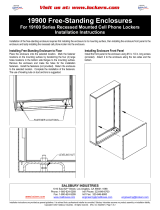
Typical Installation
Standard Dimensions (Model 2406 Shown)
Notes
1. Wall opening and lumber frame must be square.
2. Boxes should
be shielded from direct weather conditions.
3. Store keys in a safe place until ready for use.
4. Hardware is not included to fasten unit into rough opening.
Data Distribution Box Instructions
1. These data distribution boxes are to be stacked in rack ladders
secured to a platform incorporated into the wall. Allowing 25-3/8” for
the width of the first box column and 23-7/8” for each additional
column (also add for any amount of desired space on each side of
the installation), frame out the perimeter of the wall and secure to the
floor.
2. A platform 10”H x 16”D and wide enough to support the total
number of columns, should be constructed for the base of the
installation and joined with the wall frame.
3. Allowing a 61-5/8”H opening from the platform, frame out the
installation opening allowing enough room to position rack ladders
23-7/8” on center. Rack ladders should extend over the front edge
1/2” or 3/8”, depending on the thickness of the drywall to be used.
Lag bolt the bottom and top of the rack ladder to the wall. See the
illustration on the next page. The front of the rack ladder should be
flush with the drywall surface.
4. Add additional studs where needed and finish the wall with drywall.
5. Install the modules on the rack ladder assemblies from the back.
Starting at the bottom, slide the module into the rack ladder support
angles until it is tight with the front of the rack ladder. Repeat this
procedure until the column is completed and proceed to the bottom
of the next column until all modules are installed.
6. Secure the modules to the rack ladders from the rear with the
cover strips. Slide the strips over the threaded studs and fasten with
provided hex nuts. This clamps the modules into the rack ladders
and completes the installation if there is no rear cover option.
7. The purchase and installation of the trim for the front of the
modules is optional. There is enough trim in each kit for three (3)
box columns. Fasten the clips to the wall using 1” wood screws
around the perimeter of the boxes. See the illustration on the next
page. The trim should be long enough to properly frame the
installation and the corners should be mitered at a 45º angle.
SALSBURY INDUSTRIES
1010 East 62nd Street, Los Angeles, CA 90001-1598
Phone: 1-800-624-5269 Int’l Phone: 323-846-6700
Fax: 1-800-624-5299 Int’l Fax: 323-846-6800
Installation instructions are provided as general guidelines. It is advised that a professional installer be consulted. Salsbury Industries assumes no product assembly or installation liability.
Copyright © 2008 Salsbury Industries. All rights reserved. (Rev. 02, 7/10/2008)

8. The purchase and installation of the rear covers is optional. The
rear cover option includes a hinged cover attached to a lockable
cover strip on the hinge side (for an adjacent cover) and a lockable
cover strip (without cover) for a single box column or the end of a row
of boxes. See the illustration on this page. The lockable rear cover
and the lockable cover strip are installed instead of the non-lockable
cover strips that come with the rack ladders. They are installed over
the threaded studs on the rear of the rack ladder and the provided
hex nuts are installed on each threaded
stud. This also clamps the modules into the rack ladders and
completes the installation.
Trim Installation
Rack Ladder and Rear Cover Installation
SALSBURY INDUSTRIES
1010 East 62nd Street, Los Angeles, CA 90001-1598
Phone: 1-800-624-5269 Int’l Phone: 323-846-6700
Fax: 1-800-624-5299 Int’l Fax: 323-846-6800
Installation instructions are provided as general guidelines. It is advised that a professional installer be consulted. Salsbury Industries assumes no product assembly or installation liability.
Copyright © 2008 Salsbury Industries. All rights reserved. (Rev. 02, 7/10/2008)
/