Roadside Mailboxes - 4325
3-Wide Spreader Installation Instructions
U.S.P.S. APPROVED
Thank you for selecting Salsbury’s 4325 aluminum roadside mailbox. We are confident that the quality and construction of this product will provide
years of maintenance free use.
Installing Roadside Mailboxes on a 3-Wide Spreader
This instruction sheet is for installing three 4325 roadside mailboxes
on a 3-wide spreader on a bolt-mounted or in-ground pedestal
(ordered separately). Other installation instructions are available for
installing the mailboxes on a 2-wide spreader, directly to a pedestal,
in a wall or column, on a deluxe post, or on a post in a concrete
footing.
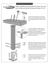
The mounting plate on the top of the pedestal has four tapped holes.
There are four 5/16” x 1-1/2” long hex washer head bolts and one 1”
thick aluminum spacer provided to fasten the middle mailbox and the
spreader to the top of the pedestal. Open the lower door of the
mailbox and install the four bolts. Make sure the bolts are sufficiently
tightened.
The other two mailboxes are each mounted to the spreader using
four 5/16” x 1-1/2” long carriage bolts, one 1” thick aluminum spacer,
flat washers, and hex acorn nuts. Two of these kits are provided with
the spreader, one for each of the mailboxes.
Set a mailbox in one of the end positions on the spreader and open
the lower door. Install the carriage bolts through the mailbox holes,
through the spacer, and through the four holes in the spreader. After
assuring that the square shanks under the bolt heads are securely in
the square holes in the bottom of the mailbox, attach the flat washers
and hex acorn nuts to the bottom of the bolts. Make sure the nuts
are sufficiently tightened.
Repeat for the remaining mailbox.
USPS Regulations
It is important to note that it is not the responsibility of mail carriers to
open mailboxes that are locked, accept keys for this purpose, or lock
mailboxes after delivery of the mail.
When you install a mailbox on a curbside or roadside, make sure that
it is easily accessible to the mail carrier. Customers are required to
contact the local post office before installing the mailbox to ensure its
correct placement and height at the street. Generally, mailboxes are
installed at a height of 41-45 inches from the road surface to the
inside floor of the point of mail entry and are set back 6-8 inches from
the front face of curb or road edge to the mailbox door.
Model 4325 Roadside Mailboxes
SALSBURY INDUSTRIES
1010 East 62
nd
Street, Los Angeles, CA 90001-1598
Phone: 1-800-624-5269 Int’l Phone: 323-846-6700
Fax: 1-800-624-5299 Int’l Fax: 323-846-6800
Installation instructions are provided as general guidelines. It is advised that a professional installer be consulted. Salsbury Industries assumes no product assembly or installation liability.
Copyright © 2010 Salsbury Industries. All rights reserved.