Page is loading ...

GTX/GTX LTR/LTS 2000™
Portable Radios
Service Manual
68P02948C90-O
© 1997 by Motorola, Inc.,
Radio Products Group
8000 W. Sunrise Blvd., Ft. Lauderdale, FL 33322
Printed in U.S.A. 2/97 All Rights Reserved.

Foreword
The information contained in this manual relates to all GTX/GTX LTR/LTS 2000™ radios, unless otherwise
specified.
Safety Information
Airbag Warning Statement
WARNING
VEHICLES EQUIPPED WITH AIR BAGS
An air bag inflates with great force. DO NOT place objects, including communication equipment, in the area over the air
bag or in the air bag deployment area. If the communication equipment is improperly installed and the air bag inflates,
this could cause serious injury.
• Installation of vehicle communication equipment should be performed by a
professional installer/technician qualified in the requirements for such installations. An air bag’s size, shape and
deployment area can vary by vehicle make, model and front
compartment configuration (e.g., bench seat vs. bucket seats).
• Contact the vehicle manufacturer’s corporate headquarters, if necessary, for specific air bag information for the vehi-
cle make, model and front compartment configuration involved in your communication equipment installation.
FCC Safety Information
The Federal Communications Commission (FCC), with its action in General Docket 79-144, March 13, 1985, has adopted
a safety standard for human exposure to radio frequency (RF) electromagnetic energy emitted by FCC-regulated equip-
ment. Motorola subscribes to the same safety standard for the use of its products. Proper operation of this radio will result
in user exposure substantially below FCC recommended limits.
• DO NOT hold the radio with the antenna very close to, or touching, exposed parts of the body, especially the face,
ears, or eyes, while transmitting. Hold the radio in a vertical position with the microphone two to three inches away
from the lips.
• DO NOT hold the transmit switch (PTT) on when not actually desiring to transmit.
• DO NOT allow children to play with any radio equipment containing a transmitter.
• DO NOT operate this equipment near electrical blasting caps or in an explosive atmosphere. Under certain condi-
tions, radios can interfere with blasting operations. When you are in the vicinity of construction work, look for, and
observe, signs cautioning against radio transmissions. If radio transmission is prohibited, you must not transmit until
out of the area. Furthermore, you must turn off your radio to prevent any accidental transmission.
• DO NOT replace or charge batteries in a hazardous atmosphere. Contact sparking may occur while installing or
removing batteries and cause an explosion.
• Turn the radio off when removing or installing a battery.
Anyone intending to use a radio in a hazardous area is advised to become familiar with the subject of intrinsic safety and
with Section 70 of the National Fire Code, which is commonly referred to as Article 500 of the National Electric Code. Use
of anything but factory supplied components may affect the approval and safety of the radio. Likewise, it is advised that
servicing should be performed only by qualified personnel who adhere to the following Factory Mutual (FM) required
warning:
WARNING
Modification of FM approved intrinsically safe radios will negate Factory Mutual
Research Corporation (FMRC) approval.
Manual Revisions
Changes which occur after this manual is printed are described in “FMRs.” These FMRs provide complete
information on changes including pertinent parts listing data.
Computer Software Copyrights
The Motorola products described in this manual may include copyrighted Motorola computer programs stored in semiconductor memo-
ries or other media. Laws in the United States and other countries preserve for Motorola certain exclusive rights for copyrighted computer
programs, including the exclusive right to copy or reproduce in any form the copyrighted computer program. Accordingly, any copy-
righted Motorola computer programs contained in the Motorola products described in this manual may not be copied or reproduced in
any manner without the express written permission of Motorola. Furthermore, the purchase of Motorola products shall not be deemed to
grant either directly or by implication, estoppel, or otherwise, any license under the copyrights, patents or patent applications of Motor-
ola, except for the normal non-exclusive royalty free license to use that arises by operation of law in the sale of a product.

©Motorola Inc., 1997
All Rights Reserved 68P02948C90-O i
Table of Contents
Foreword . . . . . . . . . . . . . . . . . . . . . . . . . . . . . . . . . . . . . . . . . . . . . . . . . . . . . . . . . . . . . . . . . . . . . . . . . . . Inside front cover
GTX and GTX LTR Portable Radios Model Chart . . . . . . . . . . . . . . . . . . . . . . . . . . . . . . . . . . . . . . . . . . . . . . . . . . v
LTS 2000 Portable Radio Model Chart. . . . . . . . . . . . . . . . . . . . . . . . . . . . . . . . . . . . . . . . . . . . . . . . . . . . . . . . . . . . vi
GTX/GTX LTR/LTS 2000 Options. . . . . . . . . . . . . . . . . . . . . . . . . . . . . . . . . . . . . . . . . . . . . . . . . . . . . . . . . . . . . . . vii
GTX/GTX LTR/LTS 2000 Accessories . . . . . . . . . . . . . . . . . . . . . . . . . . . . . . . . . . . . . . . . . . . . . . . . . . . . . . . . . . . viii
Performance Specifications: GTX/GTX LTR/LTS 2000 . . . . . . . . . . . . . . . . . . . . . . . . . . . . . . . . . . . . . . . . . . . . . x
Service Aids . . . . . . . . . . . . . . . . . . . . . . . . . . . . . . . . . . . . . . . . . . . . . . . . . . . . . . . . . . . . . . . . . . . . . . . . . . . . . . . . . . xi
Test Equipment . . . . . . . . . . . . . . . . . . . . . . . . . . . . . . . . . . . . . . . . . . . . . . . . . . . . . . . . . . . . . . . . . . . . . . . . . . . . . . . xi
Service Tools . . . . . . . . . . . . . . . . . . . . . . . . . . . . . . . . . . . . . . . . . . . . . . . . . . . . . . . . . . . . . . . . . . . . . . . . . . . . . . . . . xii
Test Set Service Cable . . . . . . . . . . . . . . . . . . . . . . . . . . . . . . . . . . . . . . . . . . . . . . . . . . . . . . . . . . . . . . . . . . . . . . xiii
Radio Model Numbering System. . . . . . . . . . . . . . . . . . . . . . . . . . . . . . . . . . . . . . . . . . . . . . . . . . . . . . . . . . . . . . . . xiv
Radio Service Software Information. . . . . . . . . . . . . . . . . . . . . . . . . . . . . . . . . . . . . . . . . . . . . . . . . . . . . . . . . . . . . . xv
Configuring the RIB and Radio. . . . . . . . . . . . . . . . . . . . . . . . . . . . . . . . . . . . . . . . . . . . . . . . . . . . . . . . . . . . . . . . . . xvi
Important Safety Information: Intrinsically Safe Radios. . . . . . . . . . . . . . . . . . . . . . . . . . . . . . . . . . . . . . . . . . . . . xvii
FMRC Approved Equipment . . . . . . . . . . . . . . . . . . . . . . . . . . . . . . . . . . . . . . . . . . . . . . . . . . . . . . . . . . . . . . . xvii
Repair of FMRC Approved Products . . . . . . . . . . . . . . . . . . . . . . . . . . . . . . . . . . . . . . . . . . . . . . . . . . . . . . . . . xviii
Repair . . . . . . . . . . . . . . . . . . . . . . . . . . . . . . . . . . . . . . . . . . . . . . . . . . . . . . . . . . . . . . . . . . . . . . . . . . . . . . . . . . . xviii
Relabeling . . . . . . . . . . . . . . . . . . . . . . . . . . . . . . . . . . . . . . . . . . . . . . . . . . . . . . . . . . . . . . . . . . . . . . . . . . . . . . . . xix
Do Not Substitute Options or Accessories . . . . . . . . . . . . . . . . . . . . . . . . . . . . . . . . . . . . . . . . . . . . . . . . . . . . xix
Vehicles Equipped with Air Bags . . . . . . . . . . . . . . . . . . . . . . . . . . . . . . . . . . . . . . . . . . . . . . . . . . . . . . . . . . . . . . . xix
Section 1
Radio Disassembly/Assembly
Overview . . . . . . . . . . . . . . . . . . . . . . . . . . . . . . . . . . . . . . . . . . . . . . . . . . . . . . . . . . . . . . . . . . . . . . . . . . . . . . . . . . . . 1-1
Safety Information. . . . . . . . . . . . . . . . . . . . . . . . . . . . . . . . . . . . . . . . . . . . . . . . . . . . . . . . . . . . . . . . . . . . . . . . . . . . . 1-1
Radio Disassembly . . . . . . . . . . . . . . . . . . . . . . . . . . . . . . . . . . . . . . . . . . . . . . . . . . . . . . . . . . . . . . . . . . . . . . . . . . . . 1-1
Battery Removal. . . . . . . . . . . . . . . . . . . . . . . . . . . . . . . . . . . . . . . . . . . . . . . . . . . . . . . . . . . . . . . . . . . . . . . . . . . 1-1
Chassis Removal. . . . . . . . . . . . . . . . . . . . . . . . . . . . . . . . . . . . . . . . . . . . . . . . . . . . . . . . . . . . . . . . . . . . . . . . . . . 1-1
Main Board Removal. . . . . . . . . . . . . . . . . . . . . . . . . . . . . . . . . . . . . . . . . . . . . . . . . . . . . . . . . . . . . . . . . . . . . . . 1-2
Front Housing Board Removal . . . . . . . . . . . . . . . . . . . . . . . . . . . . . . . . . . . . . . . . . . . . . . . . . . . . . . . . . . . . . . 1-3
Radio Reassembly. . . . . . . . . . . . . . . . . . . . . . . . . . . . . . . . . . . . . . . . . . . . . . . . . . . . . . . . . . . . . . . . . . . . . . . . . . . . . 1-3
Front Housing Reassembly. . . . . . . . . . . . . . . . . . . . . . . . . . . . . . . . . . . . . . . . . . . . . . . . . . . . . . . . . . . . . . . . . . 1-3
Chassis Reassembly. . . . . . . . . . . . . . . . . . . . . . . . . . . . . . . . . . . . . . . . . . . . . . . . . . . . . . . . . . . . . . . . . . . . . . . . 1-4
Radio Reassembly . . . . . . . . . . . . . . . . . . . . . . . . . . . . . . . . . . . . . . . . . . . . . . . . . . . . . . . . . . . . . . . . . . . . . . . . . 1-5
Section 2
Theory of Operation
Overview . . . . . . . . . . . . . . . . . . . . . . . . . . . . . . . . . . . . . . . . . . . . . . . . . . . . . . . . . . . . . . . . . . . . . . . . . . . . . . . . . . . . 2-1
Receiver . . . . . . . . . . . . . . . . . . . . . . . . . . . . . . . . . . . . . . . . . . . . . . . . . . . . . . . . . . . . . . . . . . . . . . . . . . . . . . . . . . . . . 2-1
Intermediate Frequency (IF) . . . . . . . . . . . . . . . . . . . . . . . . . . . . . . . . . . . . . . . . . . . . . . . . . . . . . . . . . . . . . . . . 2-1
Transmitter . . . . . . . . . . . . . . . . . . . . . . . . . . . . . . . . . . . . . . . . . . . . . . . . . . . . . . . . . . . . . . . . . . . . . . . . . . . . . . . . . . 2-1
Frequency Generation Unit . . . . . . . . . . . . . . . . . . . . . . . . . . . . . . . . . . . . . . . . . . . . . . . . . . . . . . . . . . . . . . . . . . . . 2-4
Controller . . . . . . . . . . . . . . . . . . . . . . . . . . . . . . . . . . . . . . . . . . . . . . . . . . . . . . . . . . . . . . . . . . . . . . . . . . . . . . . . . . . 2-5
Functions . . . . . . . . . . . . . . . . . . . . . . . . . . . . . . . . . . . . . . . . . . . . . . . . . . . . . . . . . . . . . . . . . . . . . . . . . . . . . . . . 2-5
Normal Operation . . . . . . . . . . . . . . . . . . . . . . . . . . . . . . . . . . . . . . . . . . . . . . . . . . . . . . . . . . . . . . . . . . . . . . . . . 2-5
Clock Synthesizer . . . . . . . . . . . . . . . . . . . . . . . . . . . . . . . . . . . . . . . . . . . . . . . . . . . . . . . . . . . . . . . . . . . . . . . . . 2-5

ii 68P02948C90-O February 1997
Table of Contents GTX/GTX LTR/LTS 2000 Portable Radios Service Manual
Bus Operation . . . . . . . . . . . . . . . . . . . . . . . . . . . . . . . . . . . . . . . . . . . . . . . . . . . . . . . . . . . . . . . . . . . . . . . . . . . . . 2-5
RAM . . . . . . . . . . . . . . . . . . . . . . . . . . . . . . . . . . . . . . . . . . . . . . . . . . . . . . . . . . . . . . . . . . . . . . . . . . . . . . . . . . . . . 2-5
EEPROM . . . . . . . . . . . . . . . . . . . . . . . . . . . . . . . . . . . . . . . . . . . . . . . . . . . . . . . . . . . . . . . . . . . . . . . . . . . . . . . . . 2-5
SPI Interface . . . . . . . . . . . . . . . . . . . . . . . . . . . . . . . . . . . . . . . . . . . . . . . . . . . . . . . . . . . . . . . . . . . . . . . . . . . . . . 2-6
LED Control . . . . . . . . . . . . . . . . . . . . . . . . . . . . . . . . . . . . . . . . . . . . . . . . . . . . . . . . . . . . . . . . . . . . . . . . . . . . . . 2-6
Audio & Data Circuitry . . . . . . . . . . . . . . . . . . . . . . . . . . . . . . . . . . . . . . . . . . . . . . . . . . . . . . . . . . . . . . . . . . . . 2-6
External PTT Sense Circuits . . . . . . . . . . . . . . . . . . . . . . . . . . . . . . . . . . . . . . . . . . . . . . . . . . . . . . . . . . . . . . . . . 2-6
MIC Amplifier . . . . . . . . . . . . . . . . . . . . . . . . . . . . . . . . . . . . . . . . . . . . . . . . . . . . . . . . . . . . . . . . . . . . . . . . . . . . 2-6
TX Data Circuits . . . . . . . . . . . . . . . . . . . . . . . . . . . . . . . . . . . . . . . . . . . . . . . . . . . . . . . . . . . . . . . . . . . . . . . . . . . 2-6
Sub-Audible Data (PL/DPL) . . . . . . . . . . . . . . . . . . . . . . . . . . . . . . . . . . . . . . . . . . . . . . . . . . . . . . . . . . . . . . . . 2-7
High-Speed Data. . . . . . . . . . . . . . . . . . . . . . . . . . . . . . . . . . . . . . . . . . . . . . . . . . . . . . . . . . . . . . . . . . . . . . . . . . . 2-7
DTMF Data . . . . . . . . . . . . . . . . . . . . . . . . . . . . . . . . . . . . . . . . . . . . . . . . . . . . . . . . . . . . . . . . . . . . . . . . . . . . . . . 2-7
MDC Data . . . . . . . . . . . . . . . . . . . . . . . . . . . . . . . . . . . . . . . . . . . . . . . . . . . . . . . . . . . . . . . . . . . . . . . . . . . . . . . . 2-7
RX Audio Processing and Digital Volume Control . . . . . . . . . . . . . . . . . . . . . . . . . . . . . . . . . . . . . . . . . . . . . 2-7
Audio Power Amplifier . . . . . . . . . . . . . . . . . . . . . . . . . . . . . . . . . . . . . . . . . . . . . . . . . . . . . . . . . . . . . . . . . . . . 2-8
Audio PA Muting and Output Protection . . . . . . . . . . . . . . . . . . . . . . . . . . . . . . . . . . . . . . . . . . . . . . . . . . . . . 2-8
Receive Data Circuits . . . . . . . . . . . . . . . . . . . . . . . . . . . . . . . . . . . . . . . . . . . . . . . . . . . . . . . . . . . . . . . . . . . . . . 2-8
Alert Tone Circuits . . . . . . . . . . . . . . . . . . . . . . . . . . . . . . . . . . . . . . . . . . . . . . . . . . . . . . . . . . . . . . . . . . . . . . . . 2-8
Hear Clear . . . . . . . . . . . . . . . . . . . . . . . . . . . . . . . . . . . . . . . . . . . . . . . . . . . . . . . . . . . . . . . . . . . . . . . . . . . . . . . . . . . 2-8
Transmitter Path for Radios with Hear Clear . . . . . . . . . . . . . . . . . . . . . . . . . . . . . . . . . . . . . . . . . . . . . . . . . . 2-9
Receiver Path for Radios with Hear Clear . . . . . . . . . . . . . . . . . . . . . . . . . . . . . . . . . . . . . . . . . . . . . . . . . . . . . 2-9
U550 Data Signal Routing . . . . . . . . . . . . . . . . . . . . . . . . . . . . . . . . . . . . . . . . . . . . . . . . . . . . . . . . . . . . . . . . . . 2-10
Section 3
Accessory
Overview . . . . . . . . . . . . . . . . . . . . . . . . . . . . . . . . . . . . . . . . . . . . . . . . . . . . . . . . . . . . . . . . . . . . . . . . . . . . . . . . . . . . 3-1
Description . . . . . . . . . . . . . . . . . . . . . . . . . . . . . . . . . . . . . . . . . . . . . . . . . . . . . . . . . . . . . . . . . . . . . . . . . . . . . . . . . . 3-1
Operation . . . . . . . . . . . . . . . . . . . . . . . . . . . . . . . . . . . . . . . . . . . . . . . . . . . . . . . . . . . . . . . . . . . . . . . . . . . . . . . . . . . . 3-1
Handling Precautions . . . . . . . . . . . . . . . . . . . . . . . . . . . . . . . . . . . . . . . . . . . . . . . . . . . . . . . . . . . . . . . . . . . . . . . . . 3-1
Maintenance . . . . . . . . . . . . . . . . . . . . . . . . . . . . . . . . . . . . . . . . . . . . . . . . . . . . . . . . . . . . . . . . . . . . . . . . . . . . . . . . . 3-2
Section 4
Troubleshooting
Overview . . . . . . . . . . . . . . . . . . . . . . . . . . . . . . . . . . . . . . . . . . . . . . . . . . . . . . . . . . . . . . . . . . . . . . . . . . . . . . . . . . . . 4-1
Troubleshooting Charts . . . . . . . . . . . . . . . . . . . . . . . . . . . . . . . . . . . . . . . . . . . . . . . . . . . . . . . . . . . . . . . . . . . . . . . . 4-1
Troubleshooting Flow Chart for Receiver. . . . . . . . . . . . . . . . . . . . . . . . . . . . . . . . . . . . . . . . . . . . . . . . . . . . . . 4-2
Troubleshooting Flow Chart for Transmitter. . . . . . . . . . . . . . . . . . . . . . . . . . . . . . . . . . . . . . . . . . . . . . . . . . . 4-3
Troubleshooting Flow Chart for Synthesizer. . . . . . . . . . . . . . . . . . . . . . . . . . . . . . . . . . . . . . . . . . . . . . . . . . . 4-4
Troubleshooting Flow Chart for Controller . . . . . . . . . . . . . . . . . . . . . . . . . . . . . . . . . . . . . . . . . . . . . . . . . . . . 4-5
Section 5
Radio Diagnostic Utilities
Test Mode/Entry . . . . . . . . . . . . . . . . . . . . . . . . . . . . . . . . . . . . . . . . . . . . . . . . . . . . . . . . . . . . . . . . . . . . . . . . . . . . . 5-1
Test Mode/Channel Selection . . . . . . . . . . . . . . . . . . . . . . . . . . . . . . . . . . . . . . . . . . . . . . . . . . . . . . . . . . . . . . . . . . 5-1
Test Mode/Tx Modulation . . . . . . . . . . . . . . . . . . . . . . . . . . . . . . . . . . . . . . . . . . . . . . . . . . . . . . . . . . . . . . . . . . . . . 5-2
Fail Mode . . . . . . . . . . . . . . . . . . . . . . . . . . . . . . . . . . . . . . . . . . . . . . . . . . . . . . . . . . . . . . . . . . . . . . . . . . . . . . . . . . . . 5-2
Exiting Test Mode . . . . . . . . . . . . . . . . . . . . . . . . . . . . . . . . . . . . . . . . . . . . . . . . . . . . . . . . . . . . . . . . . . . . . . . . . . . . . 5-2
Performance Checks . . . . . . . . . . . . . . . . . . . . . . . . . . . . . . . . . . . . . . . . . . . . . . . . . . . . . . . . . . . . . . . . . . . . . . . . . . . 5-3

February 1997 68P02948C90-O iii
GTX/GTX LTR/LTS 2000 Portable Radios Service Manual Table of Contents
Section 6
Maintenance
Introduction . . . . . . . . . . . . . . . . . . . . . . . . . . . . . . . . . . . . . . . . . . . . . . . . . . . . . . . . . . . . . . . . . . . . . . . . . . . . . . . . . . 6-1
Preventive Maintenance. . . . . . . . . . . . . . . . . . . . . . . . . . . . . . . . . . . . . . . . . . . . . . . . . . . . . . . . . . . . . . . . . . . . . . . . 6-1
Inspection . . . . . . . . . . . . . . . . . . . . . . . . . . . . . . . . . . . . . . . . . . . . . . . . . . . . . . . . . . . . . . . . . . . . . . . . . . . . . . . . 6-1
Cleaning . . . . . . . . . . . . . . . . . . . . . . . . . . . . . . . . . . . . . . . . . . . . . . . . . . . . . . . . . . . . . . . . . . . . . . . . . . . . . . . . . 6-1
Cleaning External Plastic Surfaces . . . . . . . . . . . . . . . . . . . . . . . . . . . . . . . . . . . . . . . . . . . . . . . . . . . . . . . . 6-1
Cleaning Internal Circuit Boards and Components . . . . . . . . . . . . . . . . . . . . . . . . . . . . . . . . . . . . . . . . . 6-1
Safe Handling of CMOS Devices . . . . . . . . . . . . . . . . . . . . . . . . . . . . . . . . . . . . . . . . . . . . . . . . . . . . . . . . . . . . . . . . 6-1
Repair Procedures and Techniques . . . . . . . . . . . . . . . . . . . . . . . . . . . . . . . . . . . . . . . . . . . . . . . . . . . . . . . . . . . . . . 6-2
General . . . . . . . . . . . . . . . . . . . . . . . . . . . . . . . . . . . . . . . . . . . . . . . . . . . . . . . . . . . . . . . . . . . . . . . . . . . . . . . . . . 6-2
Parts Replacement and Substitution . . . . . . . . . . . . . . . . . . . . . . . . . . . . . . . . . . . . . . . . . . . . . . . . . . . . . . 6-2
Rigid Circuit Boards . . . . . . . . . . . . . . . . . . . . . . . . . . . . . . . . . . . . . . . . . . . . . . . . . . . . . . . . . . . . . . . . . . . . 6-2
Chip Components . . . . . . . . . . . . . . . . . . . . . . . . . . . . . . . . . . . . . . . . . . . . . . . . . . . . . . . . . . . . . . . . . . . . . 6-2
Over-Molded Pad-Array Carrier (OMPAC) . . . . . . . . . . . . . . . . . . . . . . . . . . . . . . . . . . . . . . . . . . . . . . . 6-2
Shields . . . . . . . . . . . . . . . . . . . . . . . . . . . . . . . . . . . . . . . . . . . . . . . . . . . . . . . . . . . . . . . . . . . . . . . . . . . . . . . 6-3
Section 7
Radio Tuning Procedure
Radio Tuning Procedure . . . . . . . . . . . . . . . . . . . . . . . . . . . . . . . . . . . . . . . . . . . . . . . . . . . . . . . . . . . . . . . . . . . . . . . 7-1
General . . . . . . . . . . . . . . . . . . . . . . . . . . . . . . . . . . . . . . . . . . . . . . . . . . . . . . . . . . . . . . . . . . . . . . . . . . . . . . . . . . 7-1
Tuning Procedure . . . . . . . . . . . . . . . . . . . . . . . . . . . . . . . . . . . . . . . . . . . . . . . . . . . . . . . . . . . . . . . . . . . . . . . . . . . . . 7-2
Reference Oscillator Alignment . . . . . . . . . . . . . . . . . . . . . . . . . . . . . . . . . . . . . . . . . . . . . . . . . . . . . . . . . . . . . 7-2
Squelch . . . . . . . . . . . . . . . . . . . . . . . . . . . . . . . . . . . . . . . . . . . . . . . . . . . . . . . . . . . . . . . . . . . . . . . . . . . . . . . . . . 7-3
Transmitter Power . . . . . . . . . . . . . . . . . . . . . . . . . . . . . . . . . . . . . . . . . . . . . . . . . . . . . . . . . . . . . . . . . . . . . . . . 7-3
Transmit Deviation Balance (Compensation) & Deviation Limit . . . . . . . . . . . . . . . . . . . . . . . . . . . . . . . . . 7-3
Transmit Deviation Limit . . . . . . . . . . . . . . . . . . . . . . . . . . . . . . . . . . . . . . . . . . . . . . . . . . . . . . . . . . . . . . . . . . . 7-3
Schematic Diagrams, Circuit Board Details, & Parts Lists
Schematic Diagram for FUF5690A RF Board Wiring Diagram . . . . . . . . . . . . . . . . . . . . . . . . . . . . . . . . . . . . . . . 2
Schematic Diagram for FUF5690A RF Board, Receiver Module . . . . . . . . . . . . . . . . . . . . . . . . . . . . . . . . . . . . . . 3
Schematic Diagram for FUF5690A RF Board, Synthesizer Module . . . . . . . . . . . . . . . . . . . . . . . . . . . . . . . . . . . 4
Schematic Diagram for FUF5690A RF Board, Transmitter Module . . . . . . . . . . . . . . . . . . . . . . . . . . . . . . . . . . . 5
Schematic Diagram for FUF5690A RF Board, Hear Clear. . . . . . . . . . . . . . . . . . . . . . . . . . . . . . . . . . . . . . . . . . . . 6
Circuit Details and Parts Lists for FUF5690A RF Board . . . . . . . . . . . . . . . . . . . . . . . . . . . . . . . . . . . . . . . . . . . . . 7
Parts Lists for FUF5690A RF Board (Cont) . . . . . . . . . . . . . . . . . . . . . . . . . . . . . . . . . . . . . . . . . . . . . . . . . . . . . . . . 8
Circuit Board Details, Schematic Diagram, & Parts List for FLN8517A Battery Filter Board. . . . . . . . . . . . . . 9
Circuit Board Details & Parts List for FLN8836A Logic Board . . . . . . . . . . . . . . . . . . . . . . . . . . . . . . . . . . . . . . . 10
Schematic Diagram for FLN8836A Logic Board. . . . . . . . . . . . . . . . . . . . . . . . . . . . . . . . . . . . . . . . . . . . . . . . . . . . 11
GTX /GTX LTR Mechanical Parts List. . . . . . . . . . . . . . . . . . . . . . . . . . . . . . . . . . . . . . . . . . . . . . . . . . . . . . . . . . . . 12
GTX/GTX LTR Exploded View . . . . . . . . . . . . . . . . . . . . . . . . . . . . . . . . . . . . . . . . . . . . . . . . . . . . . . . . . . . . . . . . . 13
LTS Mechanical Parts List . . . . . . . . . . . . . . . . . . . . . . . . . . . . . . . . . . . . . . . . . . . . . . . . . . . . . . . . . . . . . . . . . . . . . . 14
LTS 2000 Exploded View . . . . . . . . . . . . . . . . . . . . . . . . . . . . . . . . . . . . . . . . . . . . . . . . . . . . . . . . . . . . . . . . . . . . . . . 15
Miscellaneous Parts Lists. . . . . . . . . . . . . . . . . . . . . . . . . . . . . . . . . . . . . . . . . . . . . . . . . . . . . . . . . . . . . . . . . . . . . . . 16
, Motorola, Private-Line, and Digital Private-Line are trademarks of Motorola, Inc.
IBM is a registered trademark, and PC DOS, PC XT/AT/Convertible and PS/2 Model 30/50/70 are trademarks of
International Business Machine Corporation.
MS-DOS is a trademark of Microsoft Corp.

iv 68P02948C90-O February 1997
Table of Contents GTX/GTX LTR/LTS 2000 Portable Radios Service Manual
This page intentionally left blank

February 1997 68P02948C90-O
v
GTX/GTX LTR/LTS 2000 Portable Radios Service Manual Foreword
GTX and GTX LTR Portable Radios Model Chart
GTX and GTX LTR Portable Radios Model Chart
GTX Portable Radio, H11WCD4CB1AN: GTX LTR Portable Radio, H11WCD4CU1AN
FUF1194 900 MHz 1.5 ppm GTX Portable Radio
FUF1199 900 MHz 1.5 ppm GTX LTR Portable Radio
HNN9628 Battery (7.5 V rechargeable)
NAF5038 1/2 Wavelength Whip 900 MHz
KIT BREAKDOWN
FUF1194 900 MHz 1.5 ppm Portable Radio: FUF1199 900 MHz 1.5 ppm GTX LTR Portable Radio:
FLN2436 Front Unit
FUF1196 1.5 ppm RF Unit
FLN8577 Miscellaneous Parts
FLN2436 Front Housing
FHN5873 Housing
FEN1650 Logic Board & I/O Unit
FSN5509 Speaker & Microphone Assembly
FLN8574 Miscellaneous Parts
FEN1650 Logic Board & I/O Unit
FLN8836 Logic Board
FLN8515 I/O Hardware
FUF1196 1.5 ppm RF Unit
FUF5690 1.5 ppm RF Board
FLN2394 Chassis Assembly
FLN8575 Shield & Parts
FLN2394 Chassis Assembly
FLN8517 Battery Filter Board
FLN8518 Chassis Hardware
Not all kits on this page will be available from the Americas Parts Division

vi
68P02948C90-O February 1997
Foreword GTX/GTX LTR/LTS 2000 Portable Radios Service Manual
LTS 2000 Portable Radio Model Chart
LTS 2000 Portable Radio Model Chart
LTS 2000 Portable Radio, H10WCH4DC5AN
FUF1195 900 MHz, 1.5 ppm Portable Radio
HNN9628 Battery (7.5 V rechargeable)
HLN8255 Belt Clip
NAF5038 1/2 Wavelength Whip 900 MHz
KIT BREAKDOWN
FUF1195 900 MHz, 1.5 ppm Portable Radio
FLN2437 Front Unit
FUF1196 1.5 ppm RF Unit
FLN8665 Miscellaneous Parts
FLN2437 Front Housing
FHN5874 Housing
FEN1651 Logic Board & I/O Unit
FSN5509 Speaker & Microphone Assembly
FLN8576 Miscellaneous Parts
FEN1651 Logic Board & I/O Unit
FLN8836 Logic Board
FLN8515 I/O Hardware
FUF1196 1.5 ppm RF Unit
FUF5690 1.5 ppm RF Board
FLN2394 Chassis Assembly
FLN8575 Shield & Parts
FLN2394 Chassis Assembly
FLN8517 Battery Filter Board
FLN8518 Chassis Hardware
Not all kits on this page will be available from the Americas Parts Division

February 1997 68P02948C90-O
vii
GTX/GTX LTR/LTS 2000 Portable Radios Service Manual Foreword
GTX/GTX LTR/LTS 2000 Options
GTX/GTX LTR/LTS 2000 Options
GTX/LTR/LTS 2000 Options
Option Description
Factory Mutual (FM) Batteries
X X H236 Fully Approved Factory Mutual Intrinsically Safe Radio (includes FA 1200 mAH
battery)
X X H73 Factory Mutual Intrinsically Safe Radio (includes 600 mAH battery)
X X H224 600 mAH Slim Battery (deletes standard battery)
Antenna
X X H112 Delete Standard Antenna
Miscellaneous
X X H415 Bulk Packaging (minimum 10 units per line item)
Chargers
X H951 Delete Standard Charger
X H437 Rapid Rate Charger, 110 V
X H438 Slow Rate Charger, 220 V
X H439 Rapid Rate Charger, 220 V
Model
GTX/GTX LTR
LTS 2000

viii
68P02948C90-O February 1997
Foreword GTX/GTX LTR/LTS 2000 Portable Radios Service Manual
GTX/GTX LTR/LTS 2000 Accessories
GTX/GTX LTR/LTS 2000 Accessories
GTX/GTX LTR/LTS 2000 Accessories
Accessory Description
Charger Pick-ups
X HTN9803 Single Unit, Rapid Charger, UK Plug, 240 V
X X HTN9702 Single Unit Standard Charger, 110 V
X X HTN9630 Single Unit, Rapid Charger, 110 V
X X HTN9812 Multiple Unit, Rapid Charger, 220 V
X X HTN9719 Vehicular Charger, Adapter/Bracket, 12 V for use with single unit rapid chargers
X X HTN9811 Multiple Unit, Rapid Charger, European Plug, 220 V
X X HTN9944 Wall Mounting Bracket for Multiple Unit Chargers
Antenna Pick-ups
X X NAF5042 806-941 MHz 1/4 Wavelength Whip
X X NAF5039 900 MHz 1/2 Wavelength Whip
Battery Pick-ups
X X HNN9628 1200 mAh High Capacity Battery
X X HNN9701 1200 mAh Fully Approved Factory Mutual Battery*
X X HNN8308 600 mAh Slimline Battery
X X HNN9808 600 mAh Fully Approved Factory Mutual Slim Battery*
Carrying Accessories Pick-ups
X X HLN9750 Nylon Belt Loop Carry Case for High Capacity Battery
X X HLN9421 DTMF Standard Leather Carry Case w/Swivel
X X HLN9426 DTMF Standard Leather Carry Case w/Swivel for Fully Approved FM 1200 mAH
X X HLN9427 DTMF Standard Leather Carry Case w/Swivel for Fully Approved FM 600 mAH
X X HLN9429 DTMF Standard Leather Carry Case w/Belt Loop for Fully Approved FM 1200 mAH
X X HLN9431 DTMF Standard Leather Carry Case w/Belt Loop for Fully Approved FM 600 mAH
X X HLN9076 Standard Molded Carry Holder with Belt Clip
X X HLN9149 Swivel Belt Loop Adapter for Use w/Carry Cases HLN9750
X X HLN9724 Belt Clip
X X TDN1002 Swiveller - includes holster, belt and strap
X HLN8255 Spring Belt Clip
X X NTN5243 Shoulder Strap (for use with all Carry Cases)
Audio/RF Accessories:
X X HMN9725 Remote Speaker Microphone w/Coil Cord and Clip Back
X X HMN9727 Earpiece without Volume Control
X X HMN9752 Earpiece with Volume Control
X HMN9754 2-Piece Surveillance Microphone, PTT and Microphone are combined in 1 Piece
X X BDN6720 Ear Receiver with /GP300 Style Connector
X X FLN8660 Audio Accessory Security Clamp
*These batteries are only compatible with portables ordered from the factory with the Factory Mutual option.
Model
GTX/GTX LTR
LTS 2000

February 1997 68P02948C90-O
ix
GTX/GTX LTR/LTS 2000 Portable Radios Service Manual Foreword
GTX/GTX LTR/LTS 2000 Accessories
Prices and availability subject to change without notice
GTX/GTX LTR/LTS 2000 Accessories (cont.)
Documentation Kits
X 68P02946C80-A GTX Portable Radio User’s Guide
X 68P02948C65-O GTX LTR Portable Radio User’s Guide
X X 68P02948C90-O GTX/GTX LTR/LCS 2000 Portable Radios Service Manual
Radio Service Software (RSS)*
X RVN4150B RSS Package for GTX and GTX LTR Radio Programming
X RVN4156B RSS Package for LCS/LTS 2000 Radio Programming
X X 68P02946C20-A LCS/LTS 2000 RSS User’s Guide
X X 68P02948C70-O GTX/GTX LTR RSS User’s Guide
X X HKN9857 Programming/Test Cable
* See RSS information for hardware details.
Model
GTX/GTX LTR
LTS 2000

x
68P02948C90-O February 1997
Foreword GTX/GTX LTR/LTS 2000 Portable Radios Service Manual
Performance Specifications: GTX/GTX LTR/LTS 2000
Performance Specifications: GTX/GTX LTR/LTS 2000
All specifications subject to change without notice
GENERAL
RECEIVER TRANSMITTER
FCC Designation: AZ489FT5781 Frequency Range: 935-941 MHz RF Power: 2.5 W
Power Supply: NiCad Battery Bandwidth 6 MHz Frequency range: 896-902 MHz
935-941 MHz
Battery Voltage:
Nominal:
Range:
7.5 V
6 to 9 V
Usable Sensitivity
(12 dB SINAD):
0.35
µ
V max. Freq. Stability
(-30+60˚C; 25˚C ref.):
±
0.00015%
Battery Drain, Typical:
Standby:
Receive:
Transmit:
68 mA
195 mA
1500 mA
Intermodulation: -60 dB Emission
(Conducted and Radiat-
ed): -47 dBc
Temperature Range:
Operating:
Storage:
-30+60˚C*
-40+85˚C
Selectivity
(12.5 kHz Adjacent
Channel): -60 dB
FM Hum and Noise
(Companion Receiver): -35 dB
Dimensions (H x W x D)
GTX (total height includes
radio, antenna adaptor, and
antenna)
LTS 2000 (total height
includes radio, antenna
adapter, and antenna)
12.86x2.32x1.09”
325.53 x59 x29.8 mm
12.86x2.32x1.17”
326.53x59x29.8 mm
Spurious Rejection: -60 dB Distortion; 5%
Weight (w/Antenna):
GTX less Battery:
GTX + Standard Battery:
GTX + HNN9701 Battery
LTS 2000 less Battery:
LTS 2000 + Standard Battery:
LTS 2000 + HNN9701 Battery:
0.69 lbs (314 gr)
1.20 lbs (544 gr)
1.38 lbs (625 gr)
0.68 lbs (310 gr)
1.19 lbs (540 gr)
1.37 lbs (621 gr)
Freq. Stability:
(-30+60˚C; 25˚C ref.)
±
0.00015%
Modulation Limiting:
2.5 kHz
Rated Audio: 500 mW Recommended Battery:
High Capacity
HNN9628
NTN7143
Distortion (At Rated
Audio):
5%
Channel Spacing 12.5 kHz
* Operating for Display: -20+60˚C

February 1997 68P02948C90-O
xi
GTX/GTX LTR/LTS 2000 Portable Radios Service Manual Foreword
Service Aids
Service Aids
The following table lists service aids recommended for working on the GTX/GTX LTR/LTS 2000.
Test Equipment
The following table lists test equipment required to service the GTX/GTX LTR/LTS 2000.
MOTOROLA NO. DESCRIPTION APPLICATION
RLN4008 Radio Interface Box Enables communication between the radio and the
computer’s serial communications adapter.
0180357A57 (120 Vac)
0180358A56 (220 Vac)
RIB Power Supply Used to supply power to the RIB.
30-80369B72 for IBM PC ATs,
or 30-80369B71 for all other
IBM PCs
Computer Interface Cable Connects the computer’s serial communications adapter to
the RIB.
RLN4438 AT to XT Computer Adapter Allows
30-80369B72 to plug into a XT style communications
port.
HKN9857 Programming / Test Cable Connects radio to RIB. And can be used as a Battery
Eliminator.
RVN4150B for GTX/LTR
RVN4156B for LTS 2000
Radio Service Software Software on 3-1/2 in. and 5-1/4 in. floppy disc.
RTX4005 Portable Test Set Enables connection to the audio/accessory jack. Allows
switching for radio testing.
RKN4034 Test Set Cable Connects radio to RTX4005B Test Box.
FLN8769 Tune and Test Fixture Enables board level maintenance
5880348B33 SMA Female to BNC Female
Adapter
Enables RF connection to radio antenna connector.
RLN4460 Test Box. Must be ordered
with 0180303E49 adaptor
assembly.
Enables connection to the audio/accessory jack. Allows
switching for radio testing.
MOTOROLA NO. DESCRIPTION CHARACTERISTICS APPLICATION
R2000, R2400, or
R2001D with trunking
option
Communications
System Analyzer
This monitor will
substitute for items with
an asterisk *
Frequency/deviation meter and signal
generator for wide-range troubleshoot-
ing and alignment
*R1049A Digital Multimeter Two meters recommended for AC/DC
voltage and current measurements
*S1100A Audio Oscillator 67 to 161.4Hz tones Used with service monitor for injection of
PL tones
*S1053D,
*SKN6009A,
*SKN6001A
AC Voltmeter, Power
Cable for meter, Test
leads for meter
1 mV to 300 V, 10-Megohm
input impedance
Audio voltage measurements
R1053 Dual-trace Oscillo-
scope
20 MHz bandwidth,
5 mV/cm - 20 V/cm
Waveform measurements
*S1350C, *ST1215B
(VHF) *ST1223B (UHF)
*T1013A
Wattmeter,
Plug-in Elements (VHF
& UHF), RF Dummy
Load
50-Ohm, +
5% accuracy
10 W, max. 0-1000 MHz,
300 W
Transmitter power output measurements
S1339A RF Millivolt Meter 100
µ
V to 3 VRF, 10 KHz to
1.2 GHz
RF level measurements
*R1013A SINAD Meter Receiver sensitivity
S1347D or
S1348D (prog)
DC Power Supply 0-20 Vdc, 0-5 Amps Bench supply for 10Vdc

xii 68P02948C90-O February 1997
Foreword GTX/GTX LTR/LTS 2000 Portable Radios Service Manual
Service Tools
Service Tools
The following table lists the tools recommended for working on this family of radios; these tools are also available
from Motorola. Note that the R-1319A workstation requires the use of a specific “heat focus head” for each of the
components on which this item is used. Each of these heat focus heads must be ordered separately. The individual
heat focus heads (and the components on which they are used) are listed at the top of the next page.
MOTOROLA NO. DESCRIPTION APPLICATION
6680387A59 Extractor, 2-contact Removal of discrete surface-mounted devices.
6680387A64 Heat controller with safety stand, or
6680387A65 Safety stand only
0180381B45 110 Vac or
0180300E06 220 Vac
MBT250 Surface-mount/ thru-hole repair
station
Temperature-controlled, self-contained solder-
ing/desoldering repair station for installation
and removal of surface-mounted devices.
8180369E97 Flux holder/applicator arrays for repair.
Allows for the proper amount of flux to be
applied to pad grid.
1105139W02 30cc plastic syringe and flux paste For use with flux holder/applicator
8180369E97.
0180386A81 Miniature digital readout soldering station
(incl. 1/64” micropoint tip)
0180386A78 Illuminated magnifying glass with lens at-
tachment
0180386A82 Anti-static grounding kit Used during all radio assembly and disassem-
bly procedures.
6684253C72 Straight prober
6680384A98 Brush
1010041A86 Solder (RMA type), 63/37, 0.020" diameter
1 lb. spool
1080370B43 RMA liquid flux
R-1319A Shields and surface-mounted component -
IC removal/rework station (order all heat
focus heads separately)
Removal of surface-mounted integrated cir-
cuits.

February 1997 68P02948C90-O
xiii
GTX/GTX LTR/LTS 2000 Portable Radios Service Manual Foreword
Service Tools
Test Set Service Cable
HEAT-FOCUS
HEADS
INSIDE DIMENSIONS
OF HEADS
USED ON MAXIMUM PRESCRIBED
HEAT SETTING
6680334B52 0.572" x 0.572" U701 Refer to Maintenance Section of Manual
for prescribed heat setting.
6680371B15 0.460" x 0.560" VCO shield SH260
6
12
14
11
2
3
4
5
1
7
8
9
5
6
7
8
9
1
14
4
3
2
12
11
(P1) DETAIL
FRONT SIDE
NOTE: Pins 2 and 7
are cut.
P1
3.5 mm plug
2.5 mm plug
33K, 1/8 W
1.0 µF
47 Ohm, 1/2W
+
sleeve
tip
sleeve
tip
NOTE: For proper speaker impedance, the RTX4005B
test set Audio out switch must be set to the “MX” position
Speaker (Hi)
Speaker (Lo)
Gnd
Mic. Audio
PTT
Figure 1. Service Cable (RKN4034A) for the Test Set (RTX4005B)
xiv
68P02948C90-O February 1997
Foreword GTX/GTX LTR/LTS 2000 Portable Radios Service Manual
Radio Model Numbering System
Radio Model Numbering System
The model number, serial number, and Motorola FCC designation number are all on a label attached to the back of
your radio.
All GTX/GTXLTR/LTS 2000 radio models are synthesized, 8-channel units that come standard with Tone Private-
Line (TPL)/Digital Private-Line (DPL) coded squelch or carrier squelch, which may be enabled/disabled on a per
channel basis. Programming changes can be made by your local dealer.
H 11WCD4CB1AN
Position 1 - Type of Unit
H = Hand-Held Portable
Model Number:
Position:
123456789101112
Position 4 - Frequency Band
Position 2 & 3 - Model Series
Position 5 - Power Level
Position 6 - Physical Package
Position 12 -
Position 10 - Feature Level
Position 8 - Primary Operation
Position 11- Version
Position 9 - Primary System Type
896-941 MHz
3 W
Standard Control with Display
Position 7 - Channel Spacing
12.5 kHz
Unique Model Variations
Standard Package
Version Letter (Alpha) - Major Change
Basic
Privacy Plus
®
Trunked Twin Type
H 10WCH4DC5AN
Position 1 - Type of Unit
H = Hand-Held Portable
Model Number:
Position:
123456789101112
Position 4 - Frequency Band
Position 2 & 3 - Model Series
Position 5 - Power Level
Position 6 - Physical Package
Position 12 -
Position 10 - Feature Level
Position 8 - Primary Operation
Position 11- Version
Position 9 - Primary System Type
896-941 MHz
3 W
Full Keypad with Display
Position 7 - Channel Spacing
12.5 kHz
Unique Model Variation
Standard Package
Version Letter (Alpha) - Major Change
Standard Package
Clear SMARTNET
™
Dual Mode Trunked
H 11WCD4CU1AN
Position 1 - Type of Unit
H = Hand-Held Portable
Model Number:
Position:
123456789101112
Position 4 - Frequency Band
Position 2 & 3 - Model Series
Position 5 - Power Level
Position 6 - Physical Package
Position 12 -
Position 10 - Feature Level
Position 8 - Primary Operation
Position 11- Version
Position 9 - LTR
896-941 MHz
3 W
Standard Control with Display
Position 7 - Channel Spacing
12.5 kHz
Unique Model Variations
Standard Package
Version Letter (Alpha) - Major Change
Basic
Trunked Twin Type
GTX
LTR
LTS 2000
February 1997 68P02948C90-O
xv
GTX/GTX LTR/LTS 2000 Portable Radios Service Manual Foreword
Radio Service Software Information
Radio Service Software Information
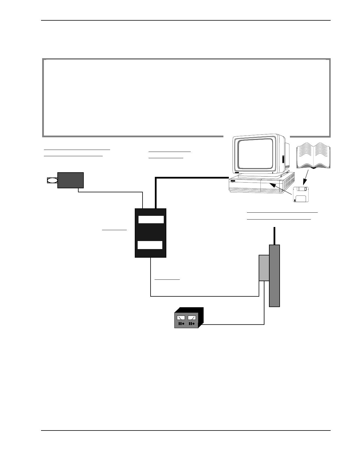
To run the Radio Service Software, you will need the following equipment:
Software
RIB Power Supply.
Plugs into 120 or 220 Vac outlet.
Computer
GTX/ GTX LTR/
RLN4008
(RIB)
30
-80369B72 or
RIB to Computer Cable.
Plugs into RIB and computer.
Connects between the RIB and radio.
Programming / Test cable.
Power Supply (7.5 Vdc)
HKN9857
RVN4150A for GTX or LTR
Note: Battery can be used on
programming cable making
power supply optional.
RSS
Manual
15 PIN
25 PIN
Required Equipment:
1. IBM XT, AT, Convertible, or System/2 Model 30/50
TM
with 512K RAM, Dual Floppy Disk Drives or one
Floppy Disk and one Hard Disk.
2. PC DOS
TM
or MS-DOS
TM
3.0 or later.
3. Radio Interface Box (RIB) RLN4008.
4. RIB to IBM AT cable 30-80369B72.
5. IBM AT cable to IBM XT computer adapter (optional) RLN4438.
6. Programming/Test cable.
7. RIB power supply 0180357A57 (120 Vac) or 0180358A56 (220 Vac).
Figure 2. Equipment Setup
LTS 2000 Radio
0180357A57 (1
20 Vac) or
0180358A56 (220 Vac)
RVN4156A for LTS 2000
30-80369B71

xvi 68P02948C90-O February 1997
Foreword GTX/GTX LTR/LTS 2000 Portable Radios Service Manual
Configuring the RIB and Radio
Configuring the RIB and Radio
1. Connect the RIB to the computer (Figure 2).
2. Plug the large 25-pin end of the HKN9857 programming cable into the RIB. The other end of this cable has
a “battery eliminator.”
3. Slide the battery eliminator in place of the radio’s battery.
4. Plug power supply 0180357A57 (120 Vac) or 0180358A56 (220 Vac) into a wall outlet, and connect the other
end to the RIB.
5. Connect the radio to a power supply and turn the volume control clockwise to turn it on.
February 1997 68P02948C90-O xvii
GTX/GTX LTR/LTS 2000 Portable Radios Service Manual Foreword
Important Safety Information: Intrinsically Safe Radios
Important Safety Information: Intrinsically Safe Radios
FMRC Approved Equipment
Anyone intending to use a radio in a location where hazardous concentrations of flammable material exist (hazardous atmo-
sphere) is advised to become familiar with the subject of intrinsic safety and with the National Electric Code NFPA 70 (National
Fire Protection Association) Article 500 (hazardous [classified] locations).
An Approval Guide, issued by Factory Mutual Research Corporation (FMRC), lists manufacturers and the products approved
by FMRC for use in such locations. FMRC has also issued a voluntary approval standard for repair service (“Class Number
3605").
FMRC Approval labels are attached to the radio to identify the unit as being FM Approved for specified hazardous atmospheres.
This label specifies the hazardous Class/Division/Group along with the part number of the battery that must be used. Their Ap-
proval mark is shown below.
Radios must ship from the Motorola manufacturing facility with the hazardous atmosphere capability and FM Approval label-
ing. Radios will not be “upgraded” to this capability and labeled in the field.
Do not operate radio communications equipment in a hazardous atmosphere
unless it is a type especially qualified (e.g. FMRC Approved) for such use. An
explosion or fire may result.
Do not operate the FMRC Approved Product in a hazardous atmosphere if it has
been physically damaged (e.g. cracked housing). An explosion or fire may result.
Do not replace or charge batteries in a hazardous atmosphere. Contact sparking
may occur while installing or removing batteries and cause an explosion or fire.
Do not replace or change accessories in a hazardous atmosphere. Contact sparking
may occur while installing or removing accessories and cause an explosion or fire.
Do not operate the FMRC Approved Product unit in a hazardous location with
the accessory contacts exposed. Keep the connector cover in place when
accessories are not used.
Turn radio off before removing or installing a battery or accessory.
Do not disassemble the FMRC Approved Product unit in any way that exposes the
internal electrical circuits of the unit.
xviii 68P02948C90-O February 1997
Foreword GTX/GTX LTR/LTS 2000 Portable Radios Service Manual
Important Safety Information: Intrinsically Safe Radios
A modification changes the unit's hardware from its original design configuration. Modifications can only be done by the orig-
inal product manufacturer at one of its FMRC audited manufacturing facilities.
Repair of FMRC Approved Products
REPAIRS FOR MOTOROLA FMRC APPROVED PRODUCTS ARE THE RESPONSIBILITY OF THE USER.
You should not repair or relabel any Motorola manufactured communication equipment bearing the FMRC Approval label
(“FMRC Approved Product”) unless you are familiar with the current FMRC Approval Standard for repair service (“Class Num-
ber 3605").
You may want to consider using a repair facility that operates under 3605 repair service approval.
FMRC's Approval Standard Class Number 3605 is subject to change at any time without notice to you, so you may want to
obtain a current copy of 3605 from FMRC. Per the December, 1994 publication of 3605, some key definitions and service re-
quirements are as follows:
Repair
A repair constitutes something done internally to the unit that would bring it back to its original condition Approved by FMRC.
A repair should be done in an FMRC Approved facility.
Items not considered as repairs are those in which an action is performed on a unit which does not require the outer casing of
the unit to be opened in a manner which exposes the internal electrical circuits of the unit. You do not have to be an FMRC
Approved Repair Facility to perform these actions.
The radio support center is at the following address:
Motorola Radio Support Center
3651 South Central Avenue
Rockford, Ill, 61102
Telephone: (800) 227-6772
(815) 489-1000
Failure to use an FMRC Approved Product unit with an FMRC Approved battery
or FMRC Approved accessories specifically approved for that product may result
in the dangerously unsafe condition of an unapproved radio combination being
used in a hazardous location.
Unauthorized or incorrect modification of an FMRC Approved Product unit will
negate the Approval rating of the product.
Incorrect repair or relabeling of any FMRC Approved Product unit could
adversely affect the Approval rating of the unit.
Use of a radio that is not intrinsically safe in a hazardous atmosphere could result
in serious injury or death.
/