Page is loading ...

GTX/GTX LTR/
LTS 2000™
Portable Radios
Service Manual
68P02945C75-A
Motorola Inc.
8000 West Sunrise Boulevard
Fort Lauderdale, Florida 33322-9934

SAFE AND EFFICIENT OPERATION OF TWO-WAY RADIOS
SCOPE
This document provides information and instructions for the safe and efficient operation of Motorola Portable two-way Radios.
The information provided in this document supersedes the general safety information contained in user guides published prior to 1st January 1998.
For information regarding radio use in a hazardous atmosphere please refer to the Factory Mutual (FM) Approval Manual Supplement or Instruction Card,
which is included with radio models that offer this capability.
EXPOSURE TO RADIO FREQUENCY ENERGY
National and International Standards and Guidelines
Your Motorola two-way Radio, which generates and radiates radio frequency (RF) electromagnetic energy (EME) is designed to comply with the following
national and international standards and guidelines regarding exposure of human beings to radio frequency electromagnetic energy:
• Federal Communications CommissionReport and Order No. FCC 96-326 (August 1996)
• American National Standards Institute (C95-1-1992)
• National Council on Radiation Protection and Measurements (NCRP - 1986)
• International Commission on Non-Ionizing Radiation Protection (ICNRP - 1986)
• European Committee for Electrotechnical Standardization (CENELEC)
- Env. 50166 - 1 1995E - Human Exposure to Electromagnetic Fields Low Frequency (0 Hz to 10kHz)
- Env. 50166 - 2 1995E - Human Exposure to Electromagnetic Fields High Frequency (10kHz to 300Ghz)
- Proceedings of SC211/8 1996 - Safety Considerations for Human Exposure to E.M.Fs from Mobile Telecommunications Equipment (M.T.E.) in the
Frequency Range 30MHz - 6GHz (E.M.F - Electromagnetic Fields)
To assure optimal radio performance and that human exposure to radio frequency electromagnetic energy is within the guidelines set forth in the above
standards, always adhere to the following procedures:
Portable Radio Operation and EME Exposure
• When transmitting with a portable radio, hold the radio in a vertical position with its microphone 1 to 2 inches (2.5 to 5.0 centimeters) away
from your mouth. Keep antenna at least 1 inch (2.5 centimeters) from your head and body.
• If you wear a portable two-way radio on your body, ensure that the antenna is at least 1 inch (2.5 centimeters) from your body when transmit-
ting.
ELECTROMAGNETIC INTERFERENCE/COMPATIBILITY
NOTE:
Nearly every electronic device is susceptible to electromagnetic interference (EMI) if inadequately shielded, designed or otherwise configured for
electromagnetic compatibility.
• To avoid electromagnetic interference and/or compatibility conflicts, turn off your radio in any facility where posted notices instruct you to do so. Hospi-
tals or health care facilities may be using equipment that is sensitive to external RF energy.
• When instructed to do so, turn off your radio when on board an aircraft. Any use of a radio must be in accordance with airline regulations or crew instruc-
tions.
OPERATIONAL WARNINGS
• FOR VEHICLES WITH AN AIR BAG
Do not place a portable radio in the area over an air bag or in the air bag deployment area. Air bags inflate with great force. If a portable radio is
placed in the air bag deployment area and the air bag inflates, the radio may be propelled with great force and cause serious injury to occupants of
the vehicle.
• POTENTIALLY EXPLOSIVE ATMOSPHERES
Turn off your two-way radio when you are in any area with a potentially explosive atmosphere, unless it is a radio type especially qualified for use
in such areas (for example, Factory Mutual Approved). Sparks in a potentially explosive atmosphere can cause an explosion or fire resulting in
bodily injury or even death.
• BATTERIES
Do not replace or charge batteries in a potentially explosive atmosphere. Contact sparking may occur while installing or removing batteries and
cause an explosion.
• BLASTING CAPS AND AREAS
To avoid possible interference with blasting operations, turn off your radio when you are near electrical blasting caps, in a blasting area, or in areas
posted: “Turn off two-way radio”. Obey all signs and instructions.
NOTE:
The areas with potentially explosive atmospheres referred to above include fueling areas such as: below decks on boats; fuel or chemical
transfer or storage facilities; areas where the air contains chemical or particles, such as grain, dust or metal powders; and any other area where you
would normally be advised to turn off your vehicle engine. Areas with potentially explosive atmospheres are often but not always posted.
OPERATIONAL CAUTIONS
• DAMAGED ANTENNAS
Do not use any portable two-way radio that has a damaged antenna. If a damaged antenna comes into contact with your skin, a minor burn can
result.
• BATTERIES
All batteries can cause property damage and/or bodily injury such as burns if a conductive material such as jewelry, keys, or beaded chains touch
exposed terminals. The conductive material may complete an electrical circuit (short circuit) and become quite hot. Exercise care in handling any
charged battery, particularly when placing it inside a pocket, purse, or other container with metal objects.
!
!

REPLACEMENT PARTS ORDERING
ORDERING INFORMATION
You can order additional components and some piece parts directly through your GTX/GTX LTR/LTS 2000 price pages. When ordering
replacement parts, include the complete identification number for all chassis, kits, and components.
If you do not know a part number, include with your order the number of the chassis or kit which contains the part, and a detailed description
of the desired component. If a Motorola part number is identified on a parts list, you should be able to order the part through Motorola Parts.
If only a generic part is listed, the part is not normally available through Motorola. If no parts list is shown, generally, no user serviceable
parts are available for the kit.
Parts Information
Motorola Parts
Manual Revisions
Changes which occur after this manual is printed are described in “IMRs.” These IMRs provide complete information on changes including
pertinent parts listing data.
Computer Software Copyrights
The Motorola products described in this manual may include copyrighted Motorola computer programs stored in semiconductor memories
or other media. Laws in the United States and other countries preserve for Motorola certain exclusive rights for copyrighted computer pro-
grams, including the exclusive right to copy or reproduce in any form the copyrighted computer program. Accordingly, any copyrighted
Motorola computer programs contained in the Motorola products described in this manual may not be copied or reproduced in any manner
without the express written permission of Motorola. Furthermore, the purchase of Motorola products shall not be deemed to grant either
directly or by implication, estoppel, or otherwise, any license under the copyrights, patents or patent applications of Motorola, except for the
normal non-exclusive royalty free license to use that arises by operation of law in the sale of a product.
Motorola Radio Support Center
3761 South Central Avenue
Rockford, IL 61102-4294
1-815-489-1000
Motorola United States Federal Government Depot
7940 Penn Randall Place
Upper Marlboro, MD 20772-2627
1-800-969-6680
1-301-736-4300
7:30 A. M. to 7:00 P. M. (Central Standard Time)
Monday through Friday (Chicago, U. S. A.)
Domestic (U. S. A.): 1-800-422-4210, or 847-538-8023
1-800-826-1913, or 410-712-6200 (Federal Government)
TELEX: 280127
FAX: 1-847-538-8198
FAX: 1-40-712-4991 (Federal Government)
Domestic (U. S. A.) after hours or weekends:
1-800-927-4357
International: 1-847-538-8023
Accessories and Aftermarket Division
(United States and Canada)
Attention: Order Processing
1313 E. Algonquin Road
Schaumburg, IL 60196
Accessories and Aftermarket Division
Attention: International Order Processing
1313 E. Algonquin Road
Schaumburg, IL 60196
Customer Service/Order Entry Parts Identification
1-800-422-4210 (Voice)
1-847-538-8198 (FAX)
1-847-538-0021 (Voice)
1-847-538-8194 (FAX)

©Motorola Inc., 1998
All Rights Reserved 68P02945C75-A
i
Table of Contents
Table of Contents........................................................................................................................................ i
Safe and Efficient Operation of Two-way Radios............................................................Inside front cover
GTX/GTX LTR Portable Radio Model Chart........................................................................................................................ v
LTS 2000/LTS 2000 SmartZone and SmartNet Plus Portable Radios Model Chart...................................................... vi
GTX/GTX LTR/LTS 2000 Options...................................................................................................................................... vii
GTX/GTX LTR/LTS 2000 Accessories .............................................................................................................................. viii
Performance Specifications...................................................................................................................................................... x
Service Aids............................................................................................................................................................................... xi
Test Equipment......................................................................................................................................................................... xi
Service Tools ............................................................................................................................................................................ xii
Test Set Service Cable .................................................................................................................................................... xiii
Radio Model Numbering System ....................................................................................................................................... xiv
Radio Service Software Information..................................................................................................................................... xv
Configuring the RIB and Radio............................................................................................................................................. xv
Notes: ...................................................................................................................................................................................... xvi
Important Safety Information: Intrinsically Safe Radios................................................................................................ xvii
FMRC Approved Equipment ...................................................................................................................................... xvii
Repair of FMRC Approved Products........................................................................................................................ xviii
Repair............................................................................................................................................................................. xviii
Relabeling......................................................................................................................................................................... xix
Do Not Substitute Options or Accessories .................................................................................................................. xix
Vehicles Equipped with Air Bags ........................................................................................................................................ xix
Section 1
Radio Disassembly/Assembly
Overview ................................................................................................................................................................................. 1-1
Safety Information.................................................................................................................................................................. 1-1
Radio Disassembly................................................................................................................................................................. 1-1
Battery Removal .............................................................................................................................................................. 1-1
Chassis Removal.............................................................................................................................................................. 1-1
Main Board Removal ...................................................................................................................................................... 1-2
Front Housing Board Removal ..................................................................................................................................... 1-3
Radio Reassembly .................................................................................................................................................................. 1-3
Front Housing Reassembly............................................................................................................................................ 1-3
Front Housing Reassembly Ñ Basic Model ................................................................................................................ 1-4
Chassis Reassembly ........................................................................................................................................................ 1-4
Radio Reassembly ........................................................................................................................................................... 1-5
Section 2
Theory of Operation
Overview ................................................................................................................................................................................. 2-1
Receiver.................................................................................................................................................................................... 2-1
Intermediate Frequency (IF) .......................................................................................................................................... 2-1
Transmitter.............................................................................................................................................................................. 2-1
Frequency Generation Unit .................................................................................................................................................. 2-4

ii
68P02945C75-A June 1999
Table of Contents GTX/GTX LTR /LTS 2000 Portable Radios Service Manual
Controller................................................................................................................................................................................ 2-5
Functions.......................................................................................................................................................................... 2-5
Normal Operation .......................................................................................................................................................... 2-5
Clock Synthesizer ........................................................................................................................................................... 2-5
Bus Operation.................................................................................................................................................................. 2-5
RAM .................................................................................................................................................................................. 2-5
EEPROM .......................................................................................................................................................................... 2-5
SPI Interface..................................................................................................................................................................... 2-6
LED Control..................................................................................................................................................................... 2-6
Audio & Data Circuitry ................................................................................................................................................. 2-6
External PTT Sense Circuits .......................................................................................................................................... 2-6
MIC Amplifier................................................................................................................................................................. 2-6
TX Data Circuits.............................................................................................................................................................. 2-6
Sub-Audible Data (PL/DPL) ........................................................................................................................................ 2-7
High-Speed Data............................................................................................................................................................. 2-7
DTMF Data ...................................................................................................................................................................... 2-7
MDC Data........................................................................................................................................................................ 2-7
RX Audio Processing and Digital Volume Control................................................................................................... 2-7
Audio Power Amplifier................................................................................................................................................. 2-8
Audio PA Muting and Output Protection .................................................................................................................. 2-8
Receive Data Circuits ..................................................................................................................................................... 2-8
Alert Tone Circuits ......................................................................................................................................................... 2-8
Section 3
Accessory
Overview................................................................................................................................................................................. 3-1
Description ............................................................................................................................................................................. 3-1
Operation ................................................................................................................................................................................ 3-1
Handling Precautions ........................................................................................................................................................... 3-1
Maintenance ........................................................................................................................................................................... 3-2
Section 4
Troubleshooting
Overview................................................................................................................................................................................. 4-1
Troubleshooting Charts ........................................................................................................................................................ 4-1
Troubleshooting Flow Chart for Receiver ........................................................................................ 4-2
Troubleshooting Flow Chart for Transmitter.................................................................................... 4-3
Troubleshooting Flow Chart for Synthesizer.................................................................................... 4-4
Troubleshooting Flow Chart for Controller...................................................................................... 4-5
Section 5
Radio Diagnostic Utilities
Test Mode/Entry ................................................................................................................................................................... 5-1
Test Mode/Channel Selection ............................................................................................................................................. 5-1
Test Mode/Tx Modulation................................................................................................................................................... 5-2
Exiting Test Mode.................................................................................................................................................................. 5-2
Fail Mode ................................................................................................................................................................................ 5-2
Performance Checks.............................................................................................................................................................. 5-3
Section 6
Maintenance
Introduction............................................................................................................................................................................ 6-1

June 1999 68P02945C75-A
iii
GTX/GTX LTR /LTS 2000 Portable Radios Service Manual
Preventive Maintenance........................................................................................................................................................ 6-1
Inspection ......................................................................................................................................................................... 6-1
Cleaning............................................................................................................................................................................ 6-1
Safe Handling of CMOS Devices ......................................................................................................................................... 6-1
Repair Procedures and Techniques ..................................................................................................................................... 6-2
General.............................................................................................................................................................................. 6-2
Over-Molded Pad-Array Carrier (OMPAC) ............................................................................................................... 6-3
Section 7
Radio Tuning Procedure
Radio Tuning Procedure ....................................................................................................................................................... 7-1
General.............................................................................................................................................................................. 7-1
Tuning Procedure................................................................................................................................................................... 7-2
Reference Oscillator Alignment .................................................................................................................................... 7-2
Squelch.............................................................................................................................................................................. 7-2
RSSI (Received Signal Strength Indicator)................................................................................................................... 7-3
Transmitter Power .......................................................................................................................................................... 7-3
Transmit Deviation Balance (Compensation) & Deviation Limit............................................................................ 7-3
Transmit Deviation Limit............................................................................................................................................... 7-3
Section 8
Schematic Diagrams, Circuit Board Details, and Parts Lists
Schematic Diagram for FUF5590A/FUF5591A RF Board Wiring Diagram......................................... 8-2
Schematic Diagram for FUF5590A/FUF5591A RF Board Receiver Module ....................................... 8-3
Schematic Diagram for FUF5590A/FUF5591A RF Board, Synthesizer Module.................................. 8-4
Schematic Diagram for FUF5590A/FUF5591A RF Board, Transmitter Module.................................. 8-5
Circuit Board Details for FUF5590A/FUF5591A, RF Board ................................................................ 8-6
Parts Lists for FUF5590A RF Board...................................................................................................... 8-7
Parts Lists for FUF5591A RF Board.................................................................................................... 8-10
Circuit Board Details, Schematic Diagram, & Parts List for FLN8517A Battery Filter Board........... 8-11
Parts Lists for FLN8517A Battery Filter Board ................................................................................... 8-11
Circuit Board Details for FLN8514A , F LN9053A, FLN9064A, HLN9859, HLN9860, FEN1648, and
FEN1656 Logic Board.......................................................................................................................... 8-12
Schematic Diagram for FLN8514A, FLN9053A, FLN9064A, HLN9859, HLN9860, FEN1648, and
FEN1656 Logic Board.......................................................................................................................... 8-13
Parts Lists for FLN8514A Logic Board................................................................................................ 8-14
Parts Lists for FLN9053A Logic Board................................................................................................ 8-14
Parts Lists for FLN9064A Logic Board................................................................................................ 8-14
GTX/GTX LTR Mechanical Parts List................................................................................................. 8-14
GTX Exploded View ............................................................................................................................ 8-14
GTX/GTX LTR Basic Model Mechanical Parts List........................................................................... 8-14
GTX Basic Model Radio Exploded View ............................................................................................ 8-14
LTS 2000 Mechanical Parts List........................................................................................................... 8-15
LTS 2000 Exploded View .................................................................................................................... 8-16
Miscellaneous Parts Lists...................................................................................................................... 8-17
Parts Lists for FHN5873A Housing (GTX/GTX LTR).................................................................. 8-17
Parts Lists for FHN5874A Housing (LTS 2000)............................................................................ 8-17
Parts Lists for FHN5978A Housing (LTS 2000 SmartZone) ......................................................... 8-17

iv
68P02945C75-A June 1999
Table of Contents GTX/GTX LTR /LTS 2000 Portable Radios Service Manual
Miscellaneous Parts Lists (cont.).......................................................................................................... 8-18
Parts Lists for FLN8574A Housing Miscellaneous Parts (GTX/GTX LTR) ................................. 8-18
Parts Lists for FLN8576A Housing Miscellaneous Parts (LTS 2000) ........................................... 8-18
Parts Lists for FLN8575A Shield & Parts ...................................................................................... 8-18
Parts Lists for FLN8577A Miscellaneous Parts (GTX/GTX LTR)................................................ 8-18
Parts Lists for FLN8665A Miscellaneous Parts (LTS 2000).......................................................... 8-18
Parts Lists for FLN8665B Miscellaneous Parts (LTS 2000 SmartZone) ....................................... 8-18
Parts Lists for FSN5509A Speaker & Microphone Assembly ....................................................... 8-18
Parts Lists for NAF5037A Antenna................................................................................................ 8-18
, Motorola, Private-Line, and Digital Private-Line are trademarks of Motorola, Inc.
IBM is a registered trademark, and PC DOS, PC XT/AT/Convertible and PS/2 Model 30/50/70 are trademarks of
International Business Machine Corporation.
MS-DOS is a trademark of Microsoft Corp.

June 1999 68P02945C75-A
v
GTX/GTX LTR /LTS 2000 Portable Radios Service Manual Foreword
GTX/GTX LTR Portable Radio Model Chart
GTX/GTX LTR Portable Radio Model Chart
Not all kits on this page will be available from the Accessories and Aftermarket Division
GTX 800MHz Portable Radio Model Chart
Model Description
H11UCC6DB1_N GTX Basic Radio, 800MHz, Privacy Plus
H11UCC6DU1_N GTX Basic Radio, 800MHz, LTR
H11UCD6CB1_N GTX Keypad Radio, 800MHz, Privacy Plus
H11UCD6CU1_N GTX Keypad Radio, 800MHz, LTR
Item Description
X HLN3140 Front Housing Assembly with Logic Board
X HLN3141 Front Housing Assembly with Logic Board
X FLN2392 Front Housing Assembly with Logic Board
X FLN2445 Front Housing Assembly with Logic Board
X HLN9859 Logic Board & I/O Unit
X HLN9860 Logic Board & I/O Unit
X FEN1648 Logic Board & I/O Unit
X FEN1656 Logic Board & I/O Unit
X X X X FUF1191 2.5 ppm RF Unit
XXXXFLN2394 Chassis Assembly
x = Indicates one of each is required.

vi
68P02945C75-A June 1999
Foreword GTX/GTX LTR /LTS 2000 Portable Radios Service Manual
LTS 2000/SmartZone and SmartNet Plus Portable Radios Model Chart
LTS 2000/SmartZone and SmartNet Plus Portable Radios
Model Chart
Not all kits on this page will be available from the Accessories and Aftermarket Division
NOTE
Items with sufÞx may be upgraded in
the future.
Model Description
H10UCH6DC5AN LTS 2000 Portable Radio (For Existing Users Only)
H10UCH6DC5BN LTS 2000 Portable Radio Q38 (SmartZoneª)
H10UCH6DC5BN LTS 2000 Portable Radio Q37 (SMARTNET Plusª)
Item Description
X FLN2395A Front Housing Assembly with Logic Board (for factory use only)
X FLN2395B Front Housing Assembly with Logic Board (for factory use only)
X FLN2550A Front Housing Assembly with Logic Board (for factory use only)
X FEN1649A Logic Board & I/O Unit (Part of FLN2395A)
X FEN1665A Logic Board & I/O Unit (Part of FLN2395B)
X FEN1667A Logic Board & I/O Unit (Part of FLN2550A)
X X X FUF1193A 1.5 ppm RF Unit
X X X FLN2394A Chassis Assembly (Part of FUF1193A)
x = Indicates one of each is required.

June 1999 68P02945C75-A
vii
GTX/GTX LTR /LTS 2000 Portable Radios Service Manual
GTX/GTX LTR/LTS 2000 Options
GTX/GTX LTR/LTS 2000 Options
GTX/GTX LTR/LTS 2000 Options
Option Description
Factory Mutual (FM) Batteries
X X H236 Fully Approved Factory Mutual Intrinsically Safe Radio (includes FA 1200 mAH
battery)
X X H73 Factory Mutual Intrinsically Safe Radio (includes 600 mAH battery)
X X H224 600 mAH Slim Battery (deletes standard battery)
Antenna
X X H112 Omit Standard Antenna
Miscellaneous
X X H415 Bulk Packaging (minimum 10 units per line item)
Chargers
X H951 Omit Standard Charger
X H437 Add Rapid Rate Charger, 110 V
X H438 Add Slow Rate Charger, 220 V
X H439 Add Rapid Rate Charger, 220 V
Model
GTX GTX/LTR
LTS 2000

viii
68P02945C75-A June 1999
Foreword GTX/GTX LTR /LTS 2000 Portable Radios Service Manual
GTX/GTX LTR/LTS 2000 Accessories
GTX/GTX LTR/LTS 2000 Accessories
GTX/GTX LTR/LTS 2000 Accessories
Accessory Description
Charger Pick-ups
X HTN9803 Single Unit, Rapid Charger, UK Plug, 240 V
X X HTN9702 Single Unit Standard Charger, 110 V
X X HTN9042 Single Unit, Rapid Charger, 110 V
X X HTN9812 Multiple Unit, Rapid Charger, 220 V
X X HTN9719 Vehicular Charger, Adapter/Bracket. 12V for use with Single Unit Rapid Chargers
X X HTN9811 Multiple Unit, Rapid Chargers, European Plug, 220V
X X HTN9944 Wall Mounting Bracket for Multiple Unit Chargers
Antenna Pick-ups
X X NAF5042 806-941 MHz 1/4 Wavelength Whip
X X NAF5037 806-870 MHz 1/2 Wavelength Whip
Battery Pick-ups
X X HNN9628 1200 mAh High Capacity Battery
X X HNN9701 1200 mAh Fully Approved Factory Mutual Battery*
X X HNN8308 600 mAh Slimline Battery
X X HNN9808 600 mAh Fully Approved Factory Mutual Slim Battery*
Carrying Accessories Pick-ups
X X HLN9421 DTMF Standard Leather Carry Case w/Swivel
X X HLN9426 DTMF Standard Leather Carry Case w/Swivel for Fully Approved FM 1200 mAH
X X HLN9427 DTMF Standard Leather Carry Case w/Swivel for Fully Approved FM 600 mAH
X X HLN9429 DTMF Standard Leather Carry Case w/Belt Loop for Fully Approved FM 1200 mAH
X X HLN9431 DTMF Standard Leather Carry Case w/Belt Loop for Fully Approved FM 600 mAH
X X HLN9076 Standard Molded Carry Holder with Belt Clip
X X HLN9149 Swivel Belt Loop Adapter for Use w/Carry Cases HLN9412, HLN9426, HLN9427
X X HLN9724 Belt Clip
X X TDN1022 Swivel - includes holster, belt and strap
X HLN8255 Spring Belt Clip
X X NTN5243 Shoulder Strap (for use with all Carry Cases)
Audio/RF Accessories:
X X HMN9030 Remote Speaker Microphone w/Coil Cord and Clip Back
X X HMN9727 Earpiece without Volume Control
X X HMN9752 Earpiece with Volume Control
X HMN9754 2-Piece Surveillance Microphone, PTT and Microphone are combined in 1 Piece
X X BDN6720 Ear Receiver with /GP300 Style Connector
X X FLN8660 Audio Accessory Security Clamp
*These batteries are only compatible with portables ordered from the factory with the Factory Mutual option.
Model
GTX/GTX LTR
LTS 2000

June 1999 68P02945C75-A
ix
GTX/GTX LTR /LTS 2000 Portable Radios Service Manual Foreword
GTX/GTX LTR/LTS 2000 Accessories
Prices and availability subject to change without notice
GTX/GTX LTR/LTS 2000 Accessories (cont.)
Documentation Kits
X 68P02946C80 GTX Portable Radio UserÕs Guide
X 68P02948C65 GTX LTR Portable Radio UserÕs Guide
X X 68P02945C75 GTX/GTX LTR/LTS 2000 Portable Radios Service Manual
X 68P02945C85 LTS 2000 Portable Radio UserÕs Guide
Radio Service Software (RSS)*
X RVN4150 GTX/GTX LTR
X RVN4156 LTS 2000
X 68P02946C20 LCS/LTS 2000 RSS UserÕs Guide
X 68P02948C70 GTX/GTX LTR RSS UserÕs Guide
X X HKN9857 Programming/Test Cable
* See RSS information for hardware details.
Model
GTX/GTX LTR
LTS 2000

x
68P02945C75-A June 1999
Foreword GTX/GTX LTR /LTS 2000 Portable Radios Service Manual
Performance Specifications
Performance Specifications
All speciÞcations subject to change without notice
GENERAL
RECEIVER TRANSMITTER
FCC Designation:
GTX /GTX LTR
LTS 2000:
AZ489FT5776
AZ489FT5777
Frequency Range: 851-870 MHz RF Power: 3 W
Power Supply: NiCad Battery Bandwidth 19 MHz Frequency range: 806-825 MHz
851-870 MHz
Battery Voltage:
Nominal:
Range:
7.5 V
6 to 9 V
Usable Sensitivity
(12 dB SINAD):
0.35
µ
V max. Freq. Stability
(-30+60ûC; 25ûC ref.:)
(821-824 MHz Capable):
±0.00025%
±0.00015%
Battery Drain, Typical:
Standby:
Receive:
Transmit:
65 mA
190 mA
1500 mA
Intermodulation: -65 dB Emission
(Conducted and Radiat-
ed): -48 dBc
Temperature Range:
Operating:
Storage:
-30+60ûC*
-40+85ûC
Selectivity
(25 kHz Adjacent
Channel): -65 dB
FM Hum and Noise
(Companion Receiver): -40 dB
Dimensions (H x W x D)
GTX (total height includes
radio, antenna adaptor, and
antenna)
LTS 2000 (total height
includes radio, antenna
adaptor, and antenna)
12.86x2.32x1.09Ó
326.53 x59 x27.8 mm
12.86x2.32x1.17Ó
326.53x59x29.8 mm
Spurious Rejection: -65 dB Distortion; 5%
Weight (w/Antenna):
GTX less Battery:
GTX + Standard Battery:
GTX + HNN9701 Battery
LTS 2000 less Battery:
LTS 2000 + Standard Battery:
LTS 2000 + HNN9701 Battery:
0.69 lbs (314 gr)
1.20 lbs (544 gr)
1.38 lbs (625 gr)
0.68 lbs (310 gr)
1.19 lbs (540 gr)
1.37 lbs (621 gr)
Freq. Stability:
(-30+60ûC; 25ûC ref.):
(821-824 MHz
Capable):
±0.00025%
±0.00015%
Modulation Limiting:
(821-824 MHz):
±
5 kHz
±
4 kHz
Rated Audio: 500 mW Recommended Battery:
High Capacity
HNN9628
NTN7143
Distortion (At Rated
Audio):
5%
Channel Spacing 25 kHz
* Operating for Display: -20+60ûC

June 1999 68P02945C75-A
xi
GTX/GTX LTR /LTS 2000 Portable Radios Service Manual Foreword
Service Aids
Service Aids
The following table lists service aids recommended for working on the GTX/GTX LTR/LTS 2000.
Test Equipment
The following table lists test equipment required to service the GTX/GTX LTR/LTS 2000.
MOTOROLA NO. DESCRIPTION APPLICATION
RLN4008 Radio Interface Box Enables communication between the radio and the
computerÕs serial communications adapter.
0180357A57 (120 Vac)
0180358A56 (220 Vac)
RIB Power Supply Used to supply power to the RIB.
30-80369B72 for IBM PC ATs,
or 30-80369B71 for all other
IBM PCs
Computer Interface Cable Connects the computerÕs serial communications adapter to
the RIB.
RLN4438 AT to XT Computer Adapter Allows
30-80369B72 to plug into a XT style communications
port.
HKN9857 Programming / Test Cable Connects radio to RIB. And can be used as a Battery
Eliminator.
RVN4150 for GTX
RVN4156 for LTS 2000
Radio Service Software Software on 3-1/2 in.
RTX4005 Portable Test Set Enables connection to the audio/accessory jack. Allows
switching for radio testing.
RKN4034 Test Set Cable Connects radio to RTX4005B Test Box.
FLN8769 Tune and Test Fixture Enables board level maintenance
5880348B33 SMA Female to BNC Female
Adapter
Enables RF connection to radio antenna connector.
MOTOROLA NO. DESCRIPTION CHARACTERISTICS APPLICATION
R2000, R2400, or
R2001D with trunking
option
Communications
System Analyzer
This monitor will
substitute for items with
an asterisk *
Frequency/deviation meter and signal
generator for wide-range troubleshoot-
ing and alignment
*R1049A Digital Multimeter Two meters recommended for AC/DC
voltage and current measurements
*S1100A Audio Oscillator 67 to 161.4Hz tones Used with service monitor for injection of
PL tones
*S1053D, *SKN6009A,
*SKN6001A
AC Voltmeter, Power
Cable for meter, Test
leads for meter
1 mV to 300 V, 10-Megohm
input impedance
Audio voltage measurements
R1053 Dual-trace Oscillo-
scope
20 MHz bandwidth,
5 mV/cm - 20 V/cm
Waveform measurements
*S1350C, *ST1215B
(VHF) *ST1223B (UHF)
*T1013A
Wattmeter,
Plug-in Elements (VHF
& UHF), RF Dummy
Load
50-Ohm, +
5% accuracy
10 W, max. 0-1000 MHz,
300 W
Transmitter power output measurements
S1339A RF Millivolt Meter 100
µ
V to 3 VRF, 10 KHz to
1.2 GHz
RF level measurements
*R1013A SINAD Meter Receiver sensitivity
S1347D or
S1348D (prog)
DC Power Supply 0-20 Vdc, 0-5 Amps Bench supply for 10Vdc

xii
68P02945C75-A June 1999
Foreword GTX/GTX LTR /LTS 2000 Portable Radios Service Manual
Service Tools
Service Tools
The following table lists the tools recommended for working on this family of radios; these tools are also available
from Motorola. Note that the R-1070A workstation requires the use of a specific Òheat focus headÓ for each of the
components on which this item is used. Each of these heat focus heads must be ordered separately. The individual
heat focus heads (and the components on which they are used) are listed at the end of the table.
MOTOROLA NO. DESCRIPTION APPLICATION
6680387A59 Extractor, 2-contact Removal of discrete surface-mounted devices.
6680387A64 Heat controller with safety stand, or
6680387A65 Safety stand only
0180381B45 110 Vac or
0180300E06 220 Vac
MBT250 Surface-mount/ thru-hole repair
station
Temperature-controlled, self-contained solder-
ing/desoldering repair station for installation
and removal of surface-mounted devices.
8180369E97 Flux holder/applicator arrays for repair.
Allows for the proper amount of ßux to be
applied to pad grid.
1105139W02 30cc plastic syringe and ßux paste For use with ßux holder/applicator
8180369E97.
0180386A81 Miniature digital readout soldering station
(incl. 1/64Ó micropoint tip)
0180386A78 Illuminated magnifying glass with lens at-
tachment
0180386A82 Anti-static grounding kit Used during all radio assembly and disassem-
bly procedures.
6684253C72 Straight prober
6680384A98 Brush
1010041A86 Solder (RMA type), 63/37, 0.020" diameter
1 lb. spool
1080370B43 RMA liquid ßux
R-1319A Shields and surface-mounted component -
IC removal/rework station (order all heat
focus heads separately)
Removal of surface-mounted integrated cir-
cuits.

June 1999 68P02945C75-A
xiii
GTX/GTX LTR /LTS 2000 Portable Radios Service Manual Foreword
Service Tools
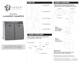
Test Set Service Cable
HEAT-FOCUS
HEADS
INSIDE DIMENSIONS
OF HEADS
USED ON MAXIMUM PRESCRIBED
HEAT SETTING
6680334B52 0.572" x 0.572" U701 Refer to Maintenance Section of Manual
for prescribed heat setting.
6680371B15 0.460" x 0.560" VCO shield SH260
6
12
14
11
2
3
4
5
1
7
8
9
5
6
7
8
9
1
14
4
3
2
12
11
(P1) DETAIL
FRONT SIDE
NOTE: Pins 2 and 7
are cut.
P1
3.5 mm plug
2.5 mm plug
33K, 1/8 W
1.0 µF
47 Ohm, 1/2W
+
sleeve
tip
sleeve
tip
NOTE: For proper speaker impedance, the RTX4005B
test set Audio out switch must be set to the “MX” position
Speaker (Hi)
Speaker (Lo)
Gnd
Mic. Audio
PTT
Figure 1. Service Cable (RKN4034A) for the Test Set (RTX4005B)

xiv
68P02945C75-A June 1999
Foreword GTX/GTX LTR /LTS 2000 Portable Radios Service Manual
Radio Model Numbering System
Radio Model Numbering System
The model number, serial number, and Motorola FCC designation number are all on a label attached to the back of your radio.
All GTX/GTX LTR/LTS 2000 radio models are synthesized, 8-channel units that come standard with Tone Private-Line (TPL)/
Digital Private-Line (DPL) coded squelch or carrier squelch, which may be enabled/disabled on a per channel basis. Program-
ming changes can be made by your local dealer
.
H 11UCD6CB1AN
Position 1 - Type of Unit
H = Hand-Held Portable
Model Number:
Position:
123456789101112
Position 4 - Frequency Band
Position 2 & 3 - Model Series
Position 5 - Power Level
Position 6 - Physical Package
Position 12 -
Position 10 - Feature Level
Position 8 - Primary Operation
Position 11- Version
Position 9 - Primary System Type
806-870 MHz
3 W
Standard Control with Display
Position 7 - Channel Spacing
20/25 kHz
Unique Model Variations
Standard Package
Version Letter (Alpha) - Major Change
Basic
Privacy Plus
¨
Trunked Twin Type
H 10UCH6DC5AN
Position 1 - Type of Unit
H = Hand-Held Portable
Model Number:
Position:
123456789101112
Position 4 - Frequency Band
Position 2 & 3 - Model Series
Position 5 - Power Level
Position 6 - Physical Package
Position 12 -
Position 10 - Feature Level
Position 8 - Primary Operation
Position 11- Version
Position 9 - Primary System Type
806-870 MHz
3 W
Full Keypad with Display
Position 7 - Channel Spacing
Unique Model Variation
Standard Package
Version Letter (Alpha/Beta ) - Major Change
Standard Package
Clear SMARTNET
ª
Dual Mode Trunked
H 11UCD6CU1AN
Position 1 - Type of Unit
H = Hand-Held Portable
Model Number:
Position:
123456789101112
Position 4 - Frequency Band
Position 2 & 3 - Model Series
Position 5 - Power Level
Position 6 - Physical Package
Position 12 -
Position 10 - Feature Level
Position 8 - Primary Operation
Position 11- Version
Position 9 - LTR
806-870 MHz
3 W
Standard Control with Display
Position 7 - Channel Spacing
25 kHz
Unique Model Variations
Standard Package
Version Letter (Alpha) - Major Change
Basic
Trunked Twin Type
LTR
LTS 2000
GTX
20/25 kHz

June 1999 68P02945C75-A
xv
GTX/GTX LTR /LTS 2000 Portable Radios Service Manual Foreword
Radio Service Software Information
Radio Service Software Information
To run the Radio Service Software, you will need the following equipment:
Configuring the RIB and Radio
1. Connect the RIB to the computer (Figure 2).
2. Plug the large 25-pin end of the HKN9857 programming cable into the RIB. The other end of this cable has
a Òbattery eliminator.Ó
3. Slide the battery eliminator in place of the radioÕs battery.
4. Plug power supply 0180357A57 (120 Vac) or 0180358A56 (220 Vac) into a wall outlet, and connect the other
end to the RIB.
5. Connect the radio to a power supply and turn the volume control clockwise to turn it on.
Software
RIB Power Supply.
Plugs into 120 or 220 Vac outlet.
Computer
GTX/GTX LTR
RLN4008
(RIB)
30-80369B72 or
RIB to Computer Cable.
Plugs into RIB and computer.
Connects between the RIB and radio.
Programming / Test cable.
Power Supply (7.5 Vdc)
HKN9857
RVN4150D for GTX/GTX LTR or
Note: Battery can be used on
programming cable making
power supply optional.
RSS
Manual
15 PIN
25 PIN
Required Equipment:
1. IBM XT, AT, Convertible, or System/2 Model 30/50
TM
with 512K RAM, Dual Floppy Disk Drives or one
Floppy Disk and one Hard Disk.
2. PC DOS
TM
or MS-DOS
TM
3.0 or later.
3. Radio Interface Box (RIB) RLN4008.
4. RIB to IBM AT cable 30-80369B72.
5. IBM AT cable to IBM XT computer adapter (optional) RLN4438.
6. Programming/Test cable.
7. RIB power supply 0180357A57 (120 Vac) or 0180358A56 (220 Vac).
Figure 2. Equipment Setup
LTS 2000 Radio
0180357A57 (1
20 Vac) or
0180358A56 (220 Vac)
RVN4156F for LTS 2000
30-80369B71

xvi
68P02945C75-A June 1999
Foreword GTX/GTX LTR /LTS 2000 Portable Radios Service Manual
Notes:
Notes:

June 1999 68P02945C75-A
xvii
GTX/GTX LTR/LTS 2000 Portable Radios Service Manual Foreword
Important Safety Information: Intrinsically Safe Radios
Important Safety Information: Intrinsically Safe Radios
FMRC Approved Equipment
Anyone intending to use a radio in a location where hazardous concentrations of flammable material exist (hazardous atmo-
sphere) is advised to become familiar with the subject of intrinsic safety and with the National Electric Code NFPA 70 (National
Fire Protection Association) Article 500 (hazardous [classified] locations).
An Approval Guide, issued by Factory Mutual Research Corporation (FMRC), lists manufacturers and the products approved
by FMRC for use in such locations. FMRC has also issued a voluntary approval standard for repair service (“Class Number
3605”).
FMRC Approval labels are attached to the radio to identify the unit as being FM Approved for specified hazardous atmospheres.
This label specifies the hazardous Class/Division/Group along with the part number of the battery that must be used. Their Ap-
proval mark is shown below.
Radios must ship from the Motorola manufacturing facility with the hazardous atmosphere capability and FM Approval label-
ing. Radios will not be “upgraded” to this capability and labeled in the field.
Do not operate radio communications equipment in a hazardous atmosphere
unless it is a type especially qualified (e.g. FMRC Approved) for such use. An
explosion or fire may result.
Do not operate the FMRC Approved Product in a hazardous atmosphere if it has
been physically damaged (e.g. cracked housing). An explosion or fire may result.
Do not replace or charge batteries in a hazardous atmosphere. Contact sparking
may occur while installing or removing batteries and cause an explosion or fire.
Do not replace or change accessories in a hazardous atmosphere. Contact sparking
may occur while installing or removing accessories and cause an explosion or fire.
Do not operate the FMRC Approved Product unit in a hazardous location with
the accessory contacts exposed. Keep the connector cover in place when
accessories are not used.
Turn radio off before removing or installing a battery or accessory.
Do not disassemble the FMRC Approved Product unit in any way that exposes the
internal electrical circuits of the unit.
!
W A R N I N G
!
/