ESAB Caddy® Mig C200i User manual
- Category
- Welding System
- Type
- User manual

0349 300 095 Valid for serial no. 932--xxx--xxxx101222
Caddy
R
RR
R
Mig C200i
S
e
r
v
i
c
e
m
a
n
u
a
l

-- 2 --
TOCe
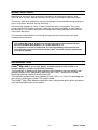
READ THIS FIRST 4. . . . . . . . . . . . . . . . . . . . . . . . . . . . . . . . . . . . . . . . . . . . . . . . . . . . . . . . . . . . . . . . .
INTRODUCTION 4. . . . . . . . . . . . . . . . . . . . . . . . . . . . . . . . . . . . . . . . . . . . . . . . . . . . . . . . . . . . . . . . . . .
TECHNICAL DATA 5. . . . . . . . . . . . . . . . . . . . . . . . . . . . . . . . . . . . . . . . . . . . . . . . . . . . . . . . . . . . . . . . .
WIRING DIAGRAM 6. . . . . . . . . . . . . . . . . . . . . . . . . . . . . . . . . . . . . . . . . . . . . . . . . . . . . . . . . . . . . . . . .
Component description 6. . . . . . . . . . . . . . . . . . . . . . . . . . . . . . . . . . . . . . . . . . . . . . . . . . . . . . . . . .
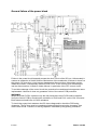
Caddyr Mig C200i 7. . . . . . . . . . . . . . . . . . . . . . . . . . . . . . . . . . . . . . . . . . . . . . . . . . . . . . . . . . . . . . .
DESCRIPTION OF OPERATION 8. . . . . . . . . . . . . . . . . . . . . . . . . . . . . . . . . . . . . . . . . . . . . . . . . . . . .
AP1:1. EMI mains filter 10. . . . . . . . . . . . . . . . . . . . . . . . . . . . . . . . . . . . . . . . . . . . . . . . . . . . . . . . . . . .
AP1:2. Pre--charge circuit 10. . . . . . . . . . . . . . . . . . . . . . . . . . . . . . . . . . . . . . . . . . . . . . . . . . . . . . . . .
AP1:3. Two--switch forward converter 10. . . . . . . . . . . . . . . . . . . . . . . . . . . . . . . . . . . . . . . . . . . . . . .
AP1:4. Current sense transformer 10. . . . . . . . . . . . . . . . . . . . . . . . . . . . . . . . . . . . . . . . . . . . . . . . . .
AP1:5. High frequency transformer 10. . . . . . . . . . . . . . . . . . . . . . . . . . . . . . . . . . . . . . . . . . . . . . . . .
AP1:6. Thermal protection sensors 11. . . . . . . . . . . . . . . . . . . . . . . . . . . . . . . . . . . . . . . . . . . . . . . . .
AP2 Analogue control board 13. . . . . . . . . . . . . . . . . . . . . . . . . . . . . . . . . . . . . . . . . . . . . . . . . . . . .
High Voltage Circuits 13. . . . . . . . . . . . . . . . . . . . . . . . . . . . . . . . . . . . . . . . . . . . . . . . . . . . . . . . . . . . . .
AP2:1H. Voltage supervision and PFC control 13. . . . . . . . . . . . . . . . . . . . . . . . . . . . . . . . . . . . . . . .
AP2:2H. Auxiliary power supply 14. . . . . . . . . . . . . . . . . . . . . . . . . . . . . . . . . . . . . . . . . . . . . . . . . . . .
AP2:3H. Thermal protection on the primary side 16. . . . . . . . . . . . . . . . . . . . . . . . . . . . . . . . . . . . . .
Low Voltage Circuits 16. . . . . . . . . . . . . . . . . . . . . . . . . . . . . . . . . . . . . . . . . . . . . . . . . . . . . . . . . . . . . .
AP2:1L. Command system 16. . . . . . . . . . . . . . . . . . . . . . . . . . . . . . . . . . . . . . . . . . . . . . . . . . . . . . . .
AP2:2L. Electromagnetic valve 18. . . . . . . . . . . . . . . . . . . . . . . . . . . . . . . . . . . . . . . . . . . . . . . . . . . . .
AP2:3L. Short arc control 19. . . . . . . . . . . . . . . . . . . . . . . . . . . . . . . . . . . . . . . . . . . . . . . . . . . . . . . . . .
AP2:4L. Wire feeder motor speed controller 22. . . . . . . . . . . . . . . . . . . . . . . . . . . . . . . . . . . . . . . . . .
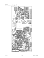
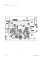
AP2 Components layout 23. . . . . . . . . . . . . . . . . . . . . . . . . . . . . . . . . . . . . . . . . . . . . . . . . . . . . . . . .
AP3 MMC panel 24. . . . . . . . . . . . . . . . . . . . . . . . . . . . . . . . . . . . . . . . . . . . . . . . . . . . . . . . . . . . . . . . .
AP3:1,2,3. Manual, digital and analog input circuits 24. . . . . . . . . . . . . . . . . . . . . . . . . . . . . . . . . . .
AP3:4. Microprocessor and its circuits 27. . . . . . . . . . . . . . . . . . . . . . . . . . . . . . . . . . . . . . . . . . . . . . .
AP3:5. Power supplies 28. . . . . . . . . . . . . . . . . . . . . . . . . . . . . . . . . . . . . . . . . . . . . . . . . . . . . . . . . . . .
AP3:6. Analog outputs 29. . . . . . . . . . . . . . . . . . . . . . . . . . . . . . . . . . . . . . . . . . . . . . . . . . . . . . . . . . . .
AP3:7. Digital outputs 30. . . . . . . . . . . . . . . . . . . . . . . . . . . . . . . . . . . . . . . . . . . . . . . . . . . . . . . . . . . . .
AP3:8. LCD display 30. . . . . . . . . . . . . . . . . . . . . . . . . . . . . . . . . . . . . . . . . . . . . . . . . . . . . . . . . . . . . .
AP3 Components layout 31. . . . . . . . . . . . . . . . . . . . . . . . . . . . . . . . . . . . . . . . . . . . . . . . . . . . . . . . .
SERVICE INSTRUCTIONS 32. . . . . . . . . . . . . . . . . . . . . . . . . . . . . . . . . . . . . . . . . . . . . . . . . . . . . . . . . .
What is ESD? 32. . . . . . . . . . . . . . . . . . . . . . . . . . . . . . . . . . . . . . . . . . . . . . . . . . . . . . . . . . . . . . . . . . .
Before the service work 32. . . . . . . . . . . . . . . . . . . . . . . . . . . . . . . . . . . . . . . . . . . . . . . . . . . . . . . . . .
Handling of the control PCB 33. . . . . . . . . . . . . . . . . . . . . . . . . . . . . . . . . . . . . . . . . . . . . . . . . . . . .
Insulation resistance measurement 33. . . . . . . . . . . . . . . . . . . . . . . . . . . . . . . . . . . . . . . . . . . . . . .
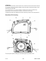
Assembly of the housing 34. . . . . . . . . . . . . . . . . . . . . . . . . . . . . . . . . . . . . . . . . . . . . . . . . . . . . . . .
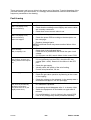
Fault tracing 35. . . . . . . . . . . . . . . . . . . . . . . . . . . . . . . . . . . . . . . . . . . . . . . . . . . . . . . . . . . . . . . . . . . .
General failure of the power block 36. . . . . . . . . . . . . . . . . . . . . . . . . . . . . . . . . . . . . . . . . . . . . . . .
INSTRUCTIONS 37. . . . . . . . . . . . . . . . . . . . . . . . . . . . . . . . . . . . . . . . . . . . . . . . . . . . . . . . . . . . . . . . . . .
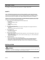
SAFETY 37. . . . . . . . . . . . . . . . . . . . . . . . . . . . . . . . . . . . . . . . . . . . . . . . . . . . . . . . . . . . . . . . . . . . . . . .
INSTALLATION 37. . . . . . . . . . . . . . . . . . . . . . . . . . . . . . . . . . . . . . . . . . . . . . . . . . . . . . . . . . . . . . . . . . . .
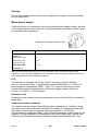
Placing 38. . . . . . . . . . . . . . . . . . . . . . . . . . . . . . . . . . . . . . . . . . . . . . . . . . . . . . . . . . . . . . . . . . . . . . . . .
Mains power supply 38. . . . . . . . . . . . . . . . . . . . . . . . . . . . . . . . . . . . . . . . . . . . . . . . . . . . . . . . . . . . .
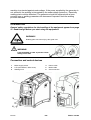
OPERATION 39. . . . . . . . . . . . . . . . . . . . . . . . . . . . . . . . . . . . . . . . . . . . . . . . . . . . . . . . . . . . . . . . . . . . . . .
Connection and control devices 39. . . . . . . . . . . . . . . . . . . . . . . . . . . . . . . . . . . . . . . . . . . . . . . . . .
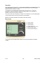
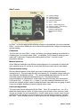
Operation 40. . . . . . . . . . . . . . . . . . . . . . . . . . . . . . . . . . . . . . . . . . . . . . . . . . . . . . . . . . . . . . . . . . . . . . .
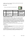
Error codes 42. . . . . . . . . . . . . . . . . . . . . . . . . . . . . . . . . . . . . . . . . . . . . . . . . . . . . . . . . . . . . . . . . . . . .
Setting the dynamics (Fe/SS) 42. . . . . . . . . . . . . . . . . . . . . . . . . . . . . . . . . . . . . . . . . . . . . . . . . . . .
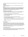
Polarity change 43. . . . . . . . . . . . . . . . . . . . . . . . . . . . . . . . . . . . . . . . . . . . . . . . . . . . . . . . . . . . . . . . .
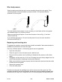
Wire feed pressure 44. . . . . . . . . . . . . . . . . . . . . . . . . . . . . . . . . . . . . . . . . . . . . . . . . . . . . . . . . . . . . .
Replacing and inserting wire 44. . . . . . . . . . . . . . . . . . . . . . . . . . . . . . . . . . . . . . . . . . . . . . . . . . . . .
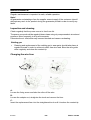
Shielding gas 45. . . . . . . . . . . . . . . . . . . . . . . . . . . . . . . . . . . . . . . . . . . . . . . . . . . . . . . . . . . . . . . . . . .
Overheating protection 45. . . . . . . . . . . . . . . . . . . . . . . . . . . . . . . . . . . . . . . . . . . . . . . . . . . . . . . . . .

-- 3 --
TOCe
MAINTENANCE 46. . . . . . . . . . . . . . . . . . . . . . . . . . . . . . . . . . . . . . . . . . . . . . . . . . . . . . . . . . . . . . . . . . . .
Inspection and cleaning 46. . . . . . . . . . . . . . . . . . . . . . . . . . . . . . . . . . . . . . . . . . . . . . . . . . . . . . . . .
Changing the wire liner 46. . . . . . . . . . . . . . . . . . . . . . . . . . . . . . . . . . . . . . . . . . . . . . . . . . . . . . . . . .
ORDERING OF SPARE PARTS 47. . . . . . . . . . . . . . . . . . . . . . . . . . . . . . . . . . . . . . . . . . . . . . . . . . . . . .
NOTES 48. . . . . . . . . . . . . . . . . . . . . . . . . . . . . . . . . . . . . . . . . . . . . . . . . . . . . . . . . . . . . . . . . . . . . . . . . . .

Edition 101222
-- 4 --
s1Cad200
READ THIS FIRST
Maintenance and repair work should be performed by an experienced person, and
electrical work only by a trained electrician. Use only recommended replacement parts.
This service manual is intended for use by technicians with electrical/electronic training for
help in connection with fault--tracing and repair.
Use the wiring diagram as a form of index for the description of operation. The circuit
board is divided into numbered blocks, which are described individually in more detail in
the description of operation. All component names in the wiring diagram are listed in the
component description.
This manual contains details of all design changes that have been made up to and
including December 2010.
The Caddyr
rr
r Mig C200i is designed and tested in accordance with international and
European standard IEC/EN 60974--1/--5/--10 and EN 61000--3--12.
On completion of service or repair work, it is the responsibility of the person(s) etc.
performing the work to ensure that the product does not depart from the requirements
of the above standard.
INTRODUCTION
Caddy
R
RR
R
Mig C200i is an inverter based, portable semiautomatic welder in a
compact design, intended for MIG/MAG welding.
The possibility of welding with homogeneous wire/shielding gas and welding with
gasless tubular wire is obtained by switching the + and -- connections on the
switching terminal close to the wire feed unit.
The machine operates with wire diameters from
∅
0,6 to
∅
1,0 mm. As shielding gas
pure argon, mixed gas or pure CO
2
may be used.
The Caddy
R
Mig C200i draws current with near--unity power factor which produces
very low level harmonics in the mains.

Edition 101222
-- 5 --
s1Cad200
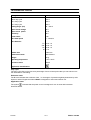
TECHNICAL DATA
Voltage 230 V, 1∼ 50/60 Hz
Permissible load at
100% duty cycle 100 A
60 % duty cycle 120 A
25 % duty cycle 180 A
Setting range (DC) 30 -- 200 A
Open circuit voltage 60 V
Open circuit power 15 W
Efficiency 82%
Power factor 0.99
Wire feed speed 2 -- 12m/min
Wire diameter
Fe
CW
Ss
Al
∅0.6--1.0
∅0.8--1.0
∅0.8--1.0
∅1.0
Bobbin size ∅200 mm
Dimensions lxwxh 449x198x347
Weight 12 kg
Operating temperature --10 to +40
o
C
Enclosure class IP 23C
Application classification
Duty cycle
The duty cycle refers to the time as a percentage of a ten--minute period that you can weld at a cer-
tain load without overloading.
Enclosure class
The IP code indicates the enclosure class, i. e. the degree of protection against penetration by solid
objects or water. Equipment marked IP23C is designed for indoor and outdoor use.
Application class
The symbol indicates that the power source is designed for use in areas with increased
electrical hazard.

Edition 101222
-- 6 --
s1Cad200
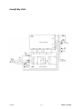
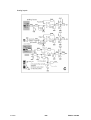
WIRING DIAGRAM
Component description
WARNING !
STATIC ELECTRICITY can damage circuit
boards and electronic components.
S
SS
S Observe precautions for handling electrostatic
sensitive devices.
S
SS
S Use proper static--proof bags and boxes.
ESD
WARNING !
High DC voltage may remain on the electrolytic capaci-
tors on the power board.
Check the voltage and discharge capacitors if needed.
AP1
Power board
AP2
Control board
AP3
MMC board
K1
Gas valve
M1
Wire feeding motor
M2
Fan
S1
Torch switch
Q1
Mains switch

Edition 101222
-- 7 --
s1Cad200
Caddyr
rr
r Mig C200i

Edition 101222
-- 8 --
s1Cad200
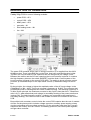
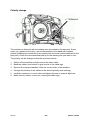
DESCRIPTION OF OPERATION
Caddyr Mig C200i
is a set of following modules:
S power PCB -- AP1
S control PCB -- AP2
S MMC panel -- AP3
S gas valve -- K1
S wire feeding motor -- M1
S fan -- M2
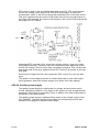
The power PCB contains all the track of energy conversion. It is supplied from the 230V
50/60Hz mains. There is the EMI filter on the input, then half--controlled thyristor bridge.
Thyristor are not fired until DC bus capacitors are not charged via pre--charge circuit.
Between the rectifier and the DC bus capacitors the boost converter is placed. It contains
the high frequency inductor, the switch (MOSFET) and the diode. Control system of the
boost converter is placed on the control PCB (AP2). The switch in boost converter control
provides: a) sinusoidal shape of the input mains current, b) stabilised voltage on the DC
bus.
By the principle, the voltage is higher the amplitude value of the AC input voltage. In the
CaddyMigs it is 390...400V. The boost converter’s frequency is 70 kHz. The converter that
provides the power to welding has two switch forward topology. The switching frequency is
70 kHz. By the principle, the maximum converter’s duty cycle is less then 50%. Transformer
ratio is 5,5:1, what means that peak voltage in secondary winding of the power transformer
is about 70V. The high frequency rectifier + inductor are connected to the transformer’s
secondary winding. The control circuits of the forward converter are included in the control
PCB.
Beyond the both converters control circuits the control PCB contains also the rest of needed
circuits. On the primary side it includes voltage supervisor, auxiliary power supply, primary
circuits overheating and overvoltage protection. On the secondary side there are: process
sequence and control, short arc control, overheating protection, wire feed speed regulator,
and gas valve controller.

Edition 101222
-- 9 --
s1Cad200

Edition 101222
-- 10 --
s1Cad200
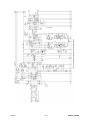
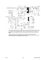
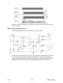
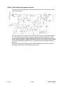
AP1:1. EMI mains filter
The EMI mains filter contains capacitors and inductors intended for suppression of
the common--mode interferences and the differential--mode interferences. The EMI
filter contains following parts: L05, C1, L01, L02, C5, C8, C16. The resistors R30,
R31 provides discharge path for the filter’s capacitors.
AP1:2. Pre--charge circuit
The pre--charge circuit contains diodes V01, V02 and PTC resistors B01, B02.
Internal diodes MV3, MV4 of the power module together with diodes V01, V02
create the non--controlled rectifier. The filter capacitors C2, C21, C22 are charged
by this rectifier via non--linear resistor B01, B02 up to the amplitude value of the
mains voltage. It is lower then the eventual DC bus voltage, nevertheless it protects
the supply mains and capacitors from the big inrush currents and makes easier
start of the PFC boost converter.
After charging of the capacitors, the auxiliary supply placed on the control PCB,
starts to work, providing also firing pulses to thyristors. The main rectifier made of
thyristors MV1, MV2, and diodes MV3, MV4 takes over the rectifying role.
The boost converter created by the inductor L03, switch MV5 (and MV6), diodes
MV7, MV8 (MV9, MV10) starts working, charging the DC bus capacitors to
390...400V.
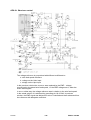
AP1:3. Two--switch forward converter
The two--switch forward converter is created on transistors MV11, MV18, and
diodes MV14, MV15. Others diodes and transistors if exists, are not activated.
There is the current sense resistor MR1 placed on the (--) placed before the PFC
converter. It’s purpose is to provide information of the momentary current to the
PFC control system what is needed for creation of the average current control loop
in the PFC control.
Drivers for the switches in the PFC and forward converters are placed on the power
PCB.
AP1:4. Current sense transformer
The current sense transformer T02 is placed on the (--) line. It senses the pulse
current, which is needed for creation of the peak current control loop in the
inverter’s control system.
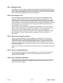
AP1:5. High frequency transformer
The high frequency transformer is mounted on the power PCB. Due to high power
soldering and anticipated high reliability, replacement of the transformer is not
subject of service routines.

Edition 101222
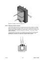
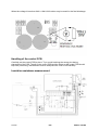
Fixing of the
PTC thermal sensor
-- 11 --
s1Cad200
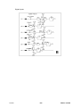
Numbers of outlets of the power transformer.
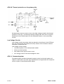
AP1:6. Thermal protection sensors
The thermal protection sensors are placed inside the power modules (or module)
and on the heatsink of the output rectifier. In the power module there are (is) NTC
(negative temperature coefficient) non--linear sensor -- 22kΩ @ 25_C, while on the
output rectifier the PTC (positive temperature coefficient) 1,0 kΩ @ 25_C linear
sensor is installed.
The replacement of the sensor in the heatsink can be carried out only along with
damaging the old sensor. The new one should be installed by means of the
electrically non--conductive and thermally conductive silicon rubber.

Edition 101222
-- 12 --
s1Cad200

Edition 101222
-- 13 --
s1Cad200
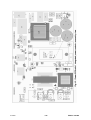
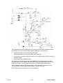
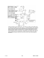
AP2 Analogue control board
The analogue control PCB contains circuits connected to the input (high voltage,
primary) and circuits connected to the output (low voltage, secondary).
High Voltage Circuits
High voltage circuits (primary side) are placed on the right part of the PCB and they
are connected to the external circuits by means of the connector CN1. High voltage
circuits contains:
S voltage supervision circuits
S PFC control circuits
S auxiliary power supply
S temperature sensors circuits
AP2:1H. Voltage supervision and PFC control
Voltage supervision circuits senses the DC bus voltage (inputs 19,20 CN1) and the
rectified input voltage (input 15 CN1). As long as voltage are not within limits high
voltage enable line (HV_ENABLE) is grounded by means of transistor Q1.
Operation of the PFC and auxiliary power supply is disabled. The reset IC4 is used
for the voltage control. Two of inputs are connected to the rectified input voltage,
one to the DC bus. Operation of the machine is disabled as long as the a.c. voltage
is less then 188 Vrms or drops under 177 Vrms (SENSE3), and DC bus voltage is
less then 259V or drops below 173V (SENSE1). Another sense input (SENSE2)
has very low time constant along with voltage limitation. It provides fast disable
during the machine switching off.

Edition 101222
-- 14 --
s1Cad200
PFC control is built on the specialised integrated circuit IC3. PFC control senses
the DC bus voltage, input current (5,6 CN1) and input voltage, providing the
constant 390...400V on the DC bus along with sinusoidal form of the input current.
This goal is achieved by the control of the switch in the boost converter placed on
the power PCB. Actually, the control circuit placed on the control PCB produces the
drive signal for PFC switch.
Specialised PFC controller (IC3), used in the present solution, does not provide
overvoltage protection. Therefore, extra two comparators were applied to control
the DC bus voltage. There is a two--step overvoltage protection. First, on the lower
level simply cuts off the drive signal from the PFC control IC by means of the logic
AND gate.
Second level is higher the first, and it resets the PFC control IC via it’s soft start
input.
The system of overvoltage protection is needed especially for work with engine
driven generator, where the voltage surges occur at the end of the welding.
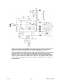
AP2:2H. Auxiliary power supply
The auxiliary power supply provides power for primary and secondary control
circuits. Basically it produces +15V supply for the primary circuits and galvanically
separated +24V supply for secondary circuit. In addition it provides firing pulses to
the thyristor in the input rectifier.
The auxiliary power supply is switched off by means of the voltage control circuit
(HV_ENABLE). Therefore thyristor firing pulses are not delivered until DC bus
capacitors are charged to the peak input voltage.

Edition 101222
-- 15 --
s1Cad200
The auxiliary power supply is built as flyback converter. Estimated maximum power
of it is 25W. The most loaded output is the +24V secondary side. It provides the
power for all low voltage control circuits and also power for the fan and the gas
valve.
The wire feeder motor is supplied from the auxiliary winding of the power
transformer. However it’s energy storage capacitor is pre--charged from the +24V,
to provide power for uninterrupted start of the motor.

Edition 101222
-- 16 --
s1Cad200
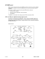
AP2:3H. Thermal protection on the primary side
As temperature sensors (sensor) are on the high voltage potential, the thermal
protection circuit (fig. ) is placed on the high voltage side, then the 0/1 signal is
transferred via the optocoupler IC2 with extended isolation, to the secondary
circuits.
Low Voltage Circuits
Low voltage circuits (secondary side) are placed on the left part of the PCB and
they are connected to the external circuits by means of the connector existed
connectors, except the CN1.
Low voltage circuits include:
S command system of the semiautomatic welder
S short arc control system
S wire feeder motor speed control circuit
S low--energy control of the electromagnetic valve
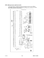
AP2:1L. Command system
Command system produces assumed program control on discrete inputs and
outputs. In particular it provides logic dependencies and generates the sequence
control of parts of the semiautomatic welder.

Edition 101222
-- 17 --
s1Cad200
The start signal from the welding torch is the basic input of the command system.
As shown on the fig. the start signal can be disabled in several cases:
S thermal protection from the primary side (IC2),
S thermal protection form the secondary side (CN4.5,6),
S torch switch is pressed during the power up (charging of the C342, hold by the
pressed switch)
S lack of the +24V_ENABLE signal
As shown any of listed cases keeps the ENABLE line low. Note that even after
removal all listed error signals, the machine is kept in disable state, until the torch
switch is released. This is additional protection of unintentional switching on.
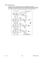
The command system is not shown entirely. The sequence of operation of the
subassemblies of the semiautomatic welder is shown on the fig.
Note that there are no proportions on this drawings.

Edition 101222
-- 18 --
s1Cad200
As shown, there is 0,2 gas pre--flow delay. The power source is kept on until the
motor is running.
AP2:2L. Electromagnetic valve
The electromagnetic valve control works in a specific mode.
As shown on the diagram the first 0,2 s coil of the valve is supplied from 24 volts
d.c. Then the generator starts running, providing 50%, 20kHz, 24V amplitude
supply of the gas welding. In result the drawn power is reduced down to1/4 of the
rated power, but the valve due to its relay--type characteristics is kept open.

Edition 101222
-- 19 --
s1Cad200
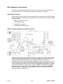
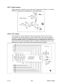
AP2:3L. Short arc control
The voltage reference is proportional with different coefficients to:
a. wire feed speed reference
b. voltage on the Umin input
c. voltage on the Upot input
In the previous solution the source a. was replaced by the EMF -- voltage
proportional to the actual wire feed speed, i.e. the EMF voltage was 0, when the
motor was stopped.
In one or either way, the voltage reference was in relation to the wire feed speed.
In the actual solution it is achieved by grounding pin 18 of CN6. In previous
solution, the EMF signal was delivered to micro controlled and then subtracted from
the reference with adequate coefficient.

Edition 101222
-- 20 --
s1Cad200
Voltage feedback is given on the CN4.1. Note that low voltage ground (GND_INV)
is connected via CN4.2 to the power supply (+). It enables creation of the summing
point in system with unipolar supply. Nevertheless the voltage feedback inverting
amplifier gives the signal in opposite phase. This signal is delivered to the next
inverting amplifier, which is not shown on the drawing. This amplifier also adds the
fraction proportional to the ramp signal, created during short circuit. In his way, a
current reference signal is delivered to the peak current mode PWM integrated
circuit IC11.
Page is loading ...
Page is loading ...
Page is loading ...
Page is loading ...
Page is loading ...
Page is loading ...
Page is loading ...
Page is loading ...
Page is loading ...
Page is loading ...
Page is loading ...
Page is loading ...
Page is loading ...
Page is loading ...
Page is loading ...
Page is loading ...
Page is loading ...
Page is loading ...
Page is loading ...
Page is loading ...
Page is loading ...
Page is loading ...
Page is loading ...
Page is loading ...
Page is loading ...
Page is loading ...
Page is loading ...
Page is loading ...
Page is loading ...
Page is loading ...
-
 1
1
-
 2
2
-
 3
3
-
 4
4
-
 5
5
-
 6
6
-
 7
7
-
 8
8
-
 9
9
-
 10
10
-
 11
11
-
 12
12
-
 13
13
-
 14
14
-
 15
15
-
 16
16
-
 17
17
-
 18
18
-
 19
19
-
 20
20
-
 21
21
-
 22
22
-
 23
23
-
 24
24
-
 25
25
-
 26
26
-
 27
27
-
 28
28
-
 29
29
-
 30
30
-
 31
31
-
 32
32
-
 33
33
-
 34
34
-
 35
35
-
 36
36
-
 37
37
-
 38
38
-
 39
39
-
 40
40
-
 41
41
-
 42
42
-
 43
43
-
 44
44
-
 45
45
-
 46
46
-
 47
47
-
 48
48
-
 49
49
-
 50
50


ESAB Caddy® Mig C200i User manual
- Category
- Welding System
- Type
- User manual
Ask a question and I''ll find the answer in the document
Finding information in a document is now easier with AI
Related papers
-
ESAB Caddy® Mig C160i User manual
-
-
-
-
-
ESAB Caddy Mig C160i User manual
-
-
-
-
Other documents
-
Ozito MWR-135 User manual
-
Abtus CAT-GA111R User Operating Manual
-
Oriental motor MDV420-24S Owner's manual
-
Cebora BRAVO 155 COMB User manual
-
-
 Akiles FlexiCloser Operating instructions
-
-
ETS 930D & 930D-FTS User manual
-
-
Eurotherm AP1 Carbon Probe User guide
