3M DBI-SALA® ExoFit™ XP Vest-Style Climbing Harness 1110204, 2X-Large, 1 EA Operating instructions
- Type
- Operating instructions

© 3M 2018
1
2
7
8
12
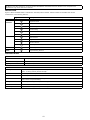
Models
1
2
3
4
5
6
7
8
9
10
11
Crossover
XS
SM
MED
LG
XL
2XL
Suspension Seat
EZ Link
Dorsal
Sternal
Shoulder
Hip
Quick Connect
Tongue Buckle
Pass-Thru Buckle
Torso Adjuster
Belt & Hip Pad
9
10
Size Attachment Elements Buckles
Belt
&
Pad
1140000 - 1140005
2
3
77
7
1140006 - 1140011
7
7
3
2
4
1140012 - 1140017
2
6
3
77
6
1140018 - 1140023
6
7
6
7
32
4
1140024 - 1140029
88
3
2
1140030 - 1140035
8
8
32
4
1140036 - 1140041
6
6
3
2
8
8
1140042 - 1140047
8
8
6
6
32
4
1140054 - 1140059
77
3
2
1140000 √
√ √ √ √
1140001 √ √ √ √ √
1140002 √ √ √ √ √
1140003 √ √ √ √ √
1140004 √ √ √ √ √
1140005 √ √ √
√ √
1140006 √ √ √ √ √ √
1140007 √ √ √ √ √ √
1140008 √ √ √ √ √ √
1140009 √ √ √ √ √ √
1140010 √ √ √ √ √
√
1140011 √ √ √ √ √ √
1140012 √ √ √ √ √ √
1140013 √ √ √ √ √ √
1140014 √ √ √ √ √ √
1140015 √ √ √ √ √ √
1140016 √ √ √
√ √ √
1140017 √ √ √ √ √ √
1140018 √ √ √ √ √ √ √
1140019 √ √ √ √ √ √ √
1140020 √ √ √ √ √ √ √
1140021 √ √ √ √ √ √
√
1140022 √ √ √ √ √ √ √
1140023 √ √ √ √ √ √ √
1140024 √ √ √ √ √
1140025 √ √ √ √ √
1140026 √ √ √ √ √
1140027 √ √ √ √
√
1140028 √ √ √ √ √
1140029 √ √ √ √ √
1140030 √ √ √ √ √ √
1140031 √ √ √ √ √ √
1140032 √ √ √ √ √ √
1140033 √ √ √ √ √ √
1140034
√ √ √ √ √ √
1140035 √ √ √ √ √ √
1140036 √ √ √ √ √ √
1140037 √ √ √ √ √ √
1140038 √ √ √ √ √ √
1140039 √ √ √ √ √ √
1140040 √
√ √ √ √ √
1140041 √ √ √ √ √ √
...
USER INSTRUCTION MANUAL
EXOFIT & EXOFIT XP
FULL BODY HARNESS
ANSI/ASSE Z359.11-2014
Form No: 5902159 Rev: J

1
2
7
8
12
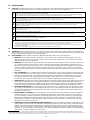
Models
1
2
3
4
5
6
7
8
9
10
11
Crossover
XS
SM
MED
LG
XL
2XL
Suspension Seat
EZ Link
Dorsal
Sternal
Shoulder
Hip
Quick Connect
Tongue Buckle
Pass-Thru Buckle
Torso Adjuster
Belt & Hip Pad
9
10
Size Attachment Elements Buckles
Belt
&
Pad
1140060 - 1140065
2
77
4
3
1140066 - 1140071
2
77
4
3
1140078 - 1140083
2
5252522525252252523
3
8
8
1140084 - 1140089
2
8
8
3
4
1140090 - 1140095
2
8
8
3
4
1140096 - 11400101
2
6
6
77
3
1140042 √ √ √ √ √ √ √
1140043 √ √ √ √ √ √ √
1140044 √ √ √ √ √ √ √
1140045 √ √ √ √ √ √ √
1140046 √ √ √ √ √ √ √
1140047 √ √ √ √ √ √ √
1140054 √ √ √ √ √ √ √ √
1140055 √ √ √ √ √ √ √ √
1140056 √ √ √ √ √ √ √ √
1140057 √ √ √
√ √ √ √ √
1140058 √ √ √ √ √ √ √ √
1140059 √ √ √ √ √ √ √ √
1140060 √ √ √ √ √ √ √
1140061 √ √ √ √ √ √ √ √
1140062 √
√ √ √ √ √ √ √
1140063 √ √ √ √ √ √ √ √
1140064 √ √ √ √ √ √ √ √
1140065 √ √ √ √ √ √ √ √
1140066 √ √ √ √ √ √ √ √
√
1140067 √ √
√
√ √ √ √
√
1140068 √ √ √ √ √ √ √ √
1140069 √ √ √ √ √ √ √ √
1140070 √ √ √ √ √ √ √ √
1140071 √ √ √ √ √ √ √ √
1140078 √ √ √ √ √ √ √
1140079 √ √ √ √ √ √ √
1140080 √ √ √ √ √ √ √
1140081 √ √ √ √ √ √ √
1140082 √ √ √ √ √
√ √
1140083 √ √ √ √ √ √ √
1140084 √ √ √ √ √ √ √
1140085 √ √ √ √ √ √ √
1140086 √ √ √ √ √ √ √
1140087 √ √ √ √ √ √ √
1140088 √
√ √ √ √ √ √
1140089 √ √ √ √ √ √ √
1140090 √ √ √ √ √ √ √ √
1140091 √ √ √ √ √ √ √ √
1140092 √ √ √ √ √ √ √ √
1140093 √ √ √ √
√ √ √ √
1140094 √ √ √ √ √ √ √ √
1140095 √ √ √ √ √ √ √ √
1140096 √ √ √ √ √ √ √ √
1140097 √ √ √ √ √ √ √ √
1140098 √ √ √ √
√ √ √ √
1140099 √ √ √ √ √ √ √ √
1140100 √ √ √ √ √ √ √ √
1140101 √ √ √ √ √ √ √ √

3
2
A B C D E F
3 4
C
B
A
FC
B
C
FC
5 6
ABC
7
A B C

4
8
A
B
C
D
9 10
1
A
CLICK
!
B
C
2
A
B

5
11
A
B
C D
E

6
12
13
1 2 3
4 5 6

7
14


FORM NO: 5908245 REV: A
9
SAFETY INFORMATION
Please read, understand, and follow all safety information contained in these instructions prior to the use of this
Full Body Harness. FAILURE TO DO SO COULD RESULT IN SERIOUS INJURY OR DEATH.
These instructions must be provided to the user of this equipment. Retain these instructions for future reference.
Intended Use:
This Full Body Harness is intended for use as part of a complete personal fall protection system.
Use in any other application including, but not limited to, material handling, recreational or sports related activities, or other
activities not described in the User Instructions, is not approved by 3M and could result in serious injury or death.
This device is only to be used by trained users in workplace applications.
! WARNING
This Full Body Harness is part of a personal fall protection system. It is expected that all users be fully trained in the safe
installation and operation of their personal fall protection system. Misuse of this device could result in serious injury
or death. For proper selection, operation, installation, maintenance, and service, refer to these User Instructions and all
manufacturer recommendations, see your supervisor, or contact 3M Technical Service.
• To reduce the risks associated with working with a Full Body Harness which, if not avoided, could result in
serious injury or death:
- Inspect the device before each use, at least annually, and after any fall event. Inspect in accordance with the User
Instructions.
- If inspection reveals an unsafe or defective condition, remove the device from service and destroy it.
- Any device that has been subject to fall arrest or impact force must be immediately removed from service and
destroyed.
- Ensure the harness is worn correctly, appropriately sized, and properly adjusted.
- Ensure all connecting subsystems (e.g. lanyards) are kept free from all hazards including, but not limited to,
entanglement with other workers, yourself, moving machinery, or other surrounding objects.
- Ensure that fall protection systems/subsystems assembled from components made by different manufacturers are
compatible and meet the requirements of applicable standards, including the ANSI Z359 or other applicable fall
protection codes, standards, or requirements. Always consult a Competent or Qualifi ed Person before using these
systems.
• To reduce the risks associated with working at height which, if not avoided, could result in serious injury or
death:
- Ensure your health and physical condition allow you to safely withstand all of the forces associated with working at
height. Consult with your doctor if you have any questions regarding your ability to use this equipment.
- Never exceed allowable capacity of your fall protection equipment.
- Never exceed maximum free fall distance of your fall protection equipment.
- Do not use any fall protection equipment that fails pre-use or other scheduled inspections, or if you have concerns about
the use or suitability of the equipment for your application. Contact 3M Technical Services with any questions.
- Some subsystem and component combinations may interfere with the operation of this equipment. Only use compatible
connections. Consult 3M prior to using this equipment in combination with components or subsystems other than those
described in the User Instructions.
- Use extra precautions when working around moving machinery (e.g. top drive of oil rigs), electrical hazards, extreme
temperatures, chemical hazards, explosive or toxic gases, sharp edges, or below overhead materials that could fall onto
you or your fall protection equipment.
- Use Arc Flash or Hot Works devices when working in high heat environments.
- Avoid surfaces and objects that can damage the user or equipment.
- Ensure there is adequate fall clearance when working at height.
- Never modify or alter your fall protection equipment. Only 3M or parties authorized in writing by 3M may make repairs to
the equipment.
- Prior to use of fall protection equipment, ensure a rescue plan is in place which allows for prompt rescue if a fall event
occurs.
- If a fall event occurs, immediately seek medical attention for the worker who has fallen.
- Do not use a body belt for fall arrest applications. Use only a Full Body Harness.
- Minimize swing falls by working as directly below the anchorage point as possible.
- If training with this device, a secondary fall protection system must be utilized in a manner that does not expose the
trainee to an unintended fall hazard.
- Always wear appropriate personal protective equipment when installing, using, or inspecting the device/system.
EN

10
Before using this equipment, record the product identifi cation information from the ID label in the “Inspection and
Maintenance Log” at the back of this manual.
DESCRIPTION
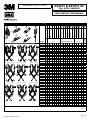
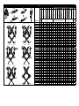
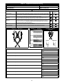
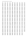
Figure 1 defi nes available ExoFit™ & Exofi t XP™ Full Body Harness models. Harness models are available with various
combinations of the following features:
Figure 1 Reference: Description:
Sizes SM, MED, LG, XL, 2XL Small, Medium, Large, Extra Large, Extra Extra Large
Attachment
Elements
1 Suspension Seat
2 EZ-Link
3 Dorsal D-Ring
4 Sternal D-Ring
5 Shoulder
6 Hip
Buckles
7 Quick Connect
8 Tongue Buckle
9 Pass-Thru Buckle
10
Torso Adjuster
Belt & Pads
11
Belt and Hip Pad
Other
12
Lanyard Parking Element
SPECIFICATIONS
Performance:
Maximum Free Fall Distance 1.8 m (6 ft)
Maximum Arresting Force 6 kN (1,349 lbs)
Capacity 140 kg (310 lbs)
Materials:
Webbing Polyester - 27 kN (6,000 lbs) Tensile Strength
Nylon - 31 kN (7,000 lbs) Tensile Strength
Pad Covers Blend of Nylon and Polyester
Label Cover Blend of Nylon and Polyester
Thread Polyester Thread on Polyester Webbing
Nylon Thread on Nylon Webbing
D-Rings Steel Alloy - 22 kN (5,000 lbs) Tensile Strength
Pass-Thru Buckle Alloy Steel
Torso Adjuster Alloy Steel - 18 kN (4,000 lbs) Tensile Strength

11
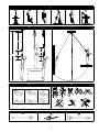
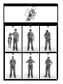
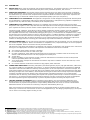
1.0 APPLICATIONS
1.1 PURPOSE: Full Body Harnesses are to be used as components in Personal Fall Protection System designed to prevent a
fall or safely arrest a fall (see Figure 2). Full Body Harnesses are used in the following applications:
A
Fall Arrest: Personal fall arrest systems typically include a Full Body Harness and a connecting subsystem (Energy Absorbing Lanyard, Self-Retracting
Device, etc.). Maximum arresting force must not exceed 1,800 lbs (8 kN).
Attachment Elements: Dorsal (feet fi rst with a 2 ft. maximum free fall when using a Self-Retracting Device or 6 ft. maximum free fall when using an
Energy Absorbing Lanyard), Sternal (feet fi rst with a 2 ft. maximum free fall), Frontal (feet fi rst with a 2 ft. maximum free fall).
B
Work Positioning: Work positioning systems typically include a Full Body Harness, positioning lanyard, and a back-up personal fall arrest system. For
work positioning applications, connect the work positioning subsystem (example: lanyard, Y-lanyard, etc.) to the lower (hip level) side or belt mounted
work positioning attachment anchorage elements (D-Rings). Never use these connection points for fall arrest.
Attachment Elements: Frontal, Hip.
C
Climbing: The Full Body Harness is used as a component of a climbing system to prevent the user from falling when climbing a ladder or other climbing
structure. Climbing systems typically include a Full Body Harness, vertical cable or rail attached to the structure, and climbing sleeve. For ladder climbing
applications, harnesses equipped with a frontal D-Ring in the sternal location may be used for fall arrest on fi xed ladder climbing systems.
Attachment Elements: Sternal
D
Rescue: The Full Body Harness is used as a component of a rescue system. Rescue systems are confi gured depending on the type of rescue. For limited
access (confi ned space) applications, harnesses equipped with D-Rings on the shoulders may be used for entry and egress into confi ned spaces where
worker profi le is an issue.
Attachment Elements: Dorsal, Sternal, Frontal, Shoulder
E
Controlled Descent: For controlled descent applications, harnesses equipped with a single sternal level D-Ring, one or two frontal mounted D-Rings, or
a pair of connectors originating below the waist (such as a seat sling) may be used for connection to a descent or evacuation system.
Attachment Elements: Dorsal Sternal, Frontal
F
Restraint: The Full Body Harness is used as a component of a restraint system to prevent the user from reaching a fall hazard. Restraint systems
typically include a Full Body Harness and a lanyard or restraint line.
Attachment Elements: Dorsal, Sternal, Frontal, Hip
Certain application and work conditions require the use of Full Body Harnesses with specifi c attributes:
• Full body harnesses with Kevlar web should be used when working with tools, materials, or environments of high temperature (foundries, chemical
manufacturing, steel fabrication, emergency rescue services, fi re services, welders, oil industry, nuclear industry, explosives).
• Harnesses with PVC coated hardware should be used when working in explosive or electrically conductive environments, or where surfaces must be
protected from the hardware.
• Harnesses with high visibility webbing should be used when increased visibility of the user is required.
1.2 STANDARDS: Harnesses included in this manual conform to the standard(s) identifi ed on the cover of this instruction.
1.3 TRAINING: It is the responsibility of the user and the purchaser of this equipment to assure that they are familiar with
these instructions, trained in the correct care and use of, and are aware of the operating characteristics, application limits,
and the consequences of improper use of this equipment.
1.4 LIMITATIONS: Always consider the following application limitations before using this equipment:
• CAPACITY: The Full Body Harness is designed for use by persons with a combined weight (clothing, tools, etc.)
ranging from 130 lbs (59 kg) to 310 lbs (140 kg)
1
. Make sure all of the components in your system are rated to a
capacity appropriate to your application.
• FREE FALL: Personal fall arrest systems used with this equipment must be rigged to limit the free fall to 6 feet (1.8
m)
2
. Restraint systems must be rigged so that no vertical free fall is possible. Work positioning systems must be
rigged so that free fall is limited to 2 feet (.6 m) or less. Personnel riding systems must be rigged so that no vertical
free fall is possible. Climbing systems must be rigged so that free fall is limited to 18 in. (.46 cm) or less. Rescue
systems must be rigged so that no vertical free fall is possible. See subsystem manufacturer’s instructions for more
information.
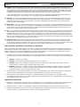
• FALL CLEARANCE: Figure 3 illustrates the components of a Fall Arrest. There must be suffi cient Fall Clearance (FC)
to arrest a fall before the user strikes the ground or other obstruction. Clearance is affected by a number of factors
including: (A) Lanyard Length, (B) Lanyard Deceleration Distance or SRL Maximum Arrest Distance, (C) Harness
Stretch and D-Ring/Connector Length and Settling (typically a Safety Factor of 1.5 ft). Refer to the instructions
included with your Lanyard or Self-Retracting Device for specifi cs regarding Fall Clearance calculation.
• SWING FALLS: Swing Falls occur when the anchorage point is not directly above the point where a fall occurs (see Figure
4). The force of striking an object in a swing fall may cause serious injury or death. Minimize swing falls by working as
directly below the anchorage point as possible. Do not permit a swing fall if injury could occur. Swing falls will signifi cantly
increase the clearance required when a Self-Retracting Device or other variable length connecting subsystem is used.
• EXTENDED SUSPENSION: A Full Body Harness is not intended for use in extended suspension applications. If the
user is going to be suspended for an extended length of time it is recommended that some form of seat support be
used. 3M recommends a seat board, suspension work seat, seat sling, or a boatswain chair. Contact 3M for more
information on these items.
• ENVIRONMENTAL HAZARDS: Use of this equipment in areas with environmental hazards may require additional
precautions to prevent injury to the user or damage to the equipment. Hazards may include, but are not limited
to; heat, chemicals, corrosive environments, high voltage power lines, gases, moving machinery, and sharp edges.
Although PVC coated and zinc plated hardware exhibit excellent corrosion resistance in chemical, acidic, alkaline,
and atmospheric conditions, frequent inspections may be required. Consult with 3M if you question the use of this
equipment in hazardous environments.
• HARNESSES FOR HIGH TEMPERATURE ENVIRONMENTS: Harnesses with Kevlar webbing are designed for use in
high temperature environments, with limitations: Kevlar webbing begins to char at 800° to 900° Fahrenheit. Kevlar
webbing can withstand limited contact exposure to temperatures up to 1,000° F. Polyester webbing loses strength
at 300° to 400° F. PVC coating on hardware has a melting point of approximately 350° F. When working with tools,
materials, or in high temperature environments, ensure that associated fall protection equipment can withstand high
temperatures, or provide protection for those items.
1 Capacity: 310 lbs (140 kg) is the maximum capacity allowed by ANSI/ASSE Z359.11. 3M harnesses are factory tested to a maximum capacity of 420 lbs (191 kg).
2 Fall Arrest Free Falls: Free falls greater than 6 ft. (1.8 m) may be permitted when users are secured to the anchorage with a connecting subsystem which limits maxi-
mum arresting force to 1,800 lbs (8 kN) and is authorized for such use (i.e., DBI-SALA Force 2™ Lanyards).

12
2.0 SYSTEM USE
2.1 RESCUE PLAN: When using this equipment and connecting subsystem(s), the employer must have a rescue plan and the
means at hand to implement and communicate that plan to users
3
, authorized persons
4
, and rescuers
5
.
2.2 INSPECTION FREQUENCY:
The Full Body Harness shall be inspected by the user before each use and by a competent
person
6
other than the user at intervals of no more than one year
7
. Inspection procedures are described in the “Inspection
and Maintenance Log”. Results of each Competent Person inspection should be recorded on copies of the “Inspection and
Maintenance Log” or tracked with a Radio Frequency Identification (RFID) system (see “Inspection”).
2.3 COMPATIBILITY OF COMPONENTS: 3M equipment is designed for use with 3M approved components and subsystems
only. Substitutions or replacements made with non-approved components or subsystems may jeopardize compatibility of
equipment and may effect the safety and reliability of the complete system.
2.4 COMPATIBILITY OF CONNECTORS: Connectors are compatible with connecting elements when they have been
designed to work together in such a way that their sizes and shapes do not cause their gate mechanisms to inadvertently
open regardless of how they become oriented. Contact Capital Safety if you have any questions about compatibility.
Connectors (hooks, carabiners, and D-Rings) must be capable of supporting at least 5,000 lbs. (22.2 kN). Connectors
must be compatible with the anchorage or other system components. Do not use equipment that is not compatible.
Non-compatible connectors may unintentionally disengage (See Figure 5). Connectors must be compatible in size, shape,
and strength. If the connecting element to which a snap hook (shown) or carabiner attaches is undersized or irregular in
shape, a situation could occur where the connecting element applies a force to the gate of the snap hook or carabiner.
This force may cause the gate (of either a self-locking or a non-locking snap hook) to open, allowing the snap hook or
carabiner to disengage from the connecting point. Self-locking snap hooks and carabiners are required.
2.5 MAKING CONNECTIONS: Use only self-locking snap hooks and carabiners with this equipment. Use only connectors that
are suitable for each application. Ensure all connections are compatible in size, shape and strength. Do not use equipment
that is not compatible. Ensure all connectors are fully closed and locked.
3M connectors (snap hooks and carabiners) are designed to be used only as specifi ed in each product’s user’s instructions.
See Figure 6 for inappropriate connections. 3M snap hooks and carabiners should not be connected:
A. To a D-Ring to which another connector is attached.
B. In a manner that would result in a load on the gate.
C. In a false engagement, where features that protrude from the snap hook or carabiner catch on the anchor, and
without visual confirmation seems to be fully engaged to the anchor point.
D. To each other.
E. Directly to webbing or rope lanyard or tie-back (unless the manufacturer’s instructions for both the lanyard and
connector specifically allows such a connection).
F. To any object which is shaped or dimensioned such that the snap hook or carabiner will not close and lock, or that
roll-out could occur.
G. In a manner that does not allow the connector to align properly while under load.
2.6 CONNECTING SUBSYSTEMS: Connecting subsystems (self-retracting lifeline, lanyard, rope grab and lifeline, cable sleeve,
etc.) must be suitable for your application (See section 1.1). See the subsystem manufacturer’s instructions for additional
information. Some harness models have web loop connection points. Do not use snap hooks to connect to web loops. Use
a self-locking carabiner to connect to a web loop. Ensure the carabiner cannot cross-gate load (load against the gate rather
than along the major axis of the carabiner). Some lanyards are designed to choke onto a web loop to provide a compatible
connection. Lanyards may be sewn directly to the web loop forming a permanent connection. Do not make multiple
connections onto one web loop, unless choking two lanyards onto a properly sized web loop. To choke the lanyard on a web
loop (Figure 7): A) Insert the lanyard web loop through the web loop or D-Ring on the harness. B) Insert the appropriate
end of the lanyard through the lanyard web loop. C) Pull the lanyard through the connecting web loop to secure.
2.7 LANYARD PARKING ATTACHMENT: Figure 8 illustrates Lanyard Parking. The Lanyard Parking Attachment is for
attaching the free end of a Lanyard or harness mounted Self-Retracting Device when not connected to an Anchorage
Connection Point for purposes of fall protection. Lanyard Parking Attachments must never be used as a Fall Protection
Attachment Element on the Harness for connecting a Lanyard or Self-Retracting Device (A).
When not connected to an Anchorage Connection Point, an unconnected Lanyard Leg must be properly parked on the
harness (B) or secured in the user’s hand as in 100% Tie-Off applications (C). Free hanging Lanyard Legs (D) can trip the
user or catch on surrounding objects resulting in a fall.
3 User: A person who performs activities at heights while protected by a personal fall protection system.
4 Authorized Person: A person assigned by the employer to perform duties at a location where the person will be exposed to a fall hazard.
5 Rescuer: Person or persons other than the rescue subject acting to perform an assisted rescue by operation of a rescue system.
6 Competent Person: One who is capable of identifying existing and predictable hazards in the surroundings or working conditions which are unsanitary, hazardous, or
dangerous to employees, and who has authorization to take prompt corrective measures to eliminate them.
7 Inspection Frequency: Extreme working conditions (harsh environments, prolonged use, etc.) may require increasing the frequency of competent person inspections.

13
3.0 HARNESS USE
3.1 BEFORE EACH USE of this equipment inspect it according to the “Inspection and Maintenance Log” (Table 1).
3.2 PLAN your system before use. Consider all factors that will affect your safety during use of this equipment. The following
list gives important points to consider when planning your system:
• Anchorage: Select an anchorage capable of sustaining the Static Load requirements of the intended fall protection
application (see Section 1.1). The anchorage location should address Free Fall, Fall Clearance, Swing Fall, and
Environmental limitations described in Section 1.4.
• Sharp Edges: Avoid working where system components may be in contact with, or abrade against, unprotected
sharp edges.
• After A Fall: Components which have been subjected to the forces of arresting a fall must be removed from service
and destroyed.
• Rescue: The employer must have a rescue plan when using this equipment. The employer must have the ability to
perform a rescue quickly and safely.
• Rescue Harness: Rescue Harnesses are intended to be worn during normal work activities. Before using rescue
attachment elements for the fi rst time, the user should carry out a suspension test in safe conditions to ensure the
harness is sized and fi tted for optimal comfort during suspension.
3.3 BUCKLES: Full Body Harnesses are equipped with Quick Connect Buckles for fastening and adjusting Leg Straps and
Chest Straps. Harness Body Belts have a Tongue Buckle. See Figure 1 for the buckle types on your Harness. Figure 9
illustrates operation of each of the following buckles:
1. Quick Connect Buckles:
A. To fasten the Quick Connect Buckle, insert the Tab into the Receptor until a click is heard.
B. To adjust the attached Web Strap: Pull the Web Strap forward or backward through the Buckle Slot to tighten or
loosen.
C. To release the Quick Connect Buckle: Squeeze the Lock Levers on each side of the Receptor. Pull the Tab out of
the Receptor.
2. Tongue Buckles: Fasten and adjust Tongue Buckles by passing the Tongue through the Buckle Frame and inserting
the Prong through the desired Grommet in the Tongue.
3.4 ADJUSTMENTS: Harnesses are equipped with a pair of Parachute Style™ Torso Adjusters for adjusting the Shoulder
Straps. Figure 10 illustrates adjustment of the Parachute Style Torso Adjusters:
1. Parachute Style Torso Adjusters: To adjust the Shoulder Straps with the Parachute Style Torso Adjusters:
A. Pull on the free strap to tighten the Shoulder Strap. To loosen the Shoulder Strap, pull on the free strap and then
back the strap through the Parachute Adjuster.
B. When properly adjusted, secure the free strap in the Strap Keeper
3.5 EASY-LINK™ ATTACHMENTS: Full Body Harnesses are equipped with a patented Easy-Link™ System that integrates
the Dorsal D-Ring with attachment elements for Harness-Mounted Self-Retracting Devices (SRDs). Figure 11 illustrates
attachment of the following 3M and Protecta Self-Retracting Devices: (A) 3M Nano-Lok™ Edge SRDs, (B) 3M Twin
Nano-Lok™ SRDs, (C) 3M Single Nano-Lok™ SRDs, (D) Protecta Twin Rebel™ SRDs, (E) 3M Twin Talon™ SRD. Other
manufacturers’ SRDs can also be mounted on the Harness in similar fashion. See the SRD manufacturer’s instructions for
requirements and installation instructions specifi c to the SRD.
Contact 3M with any questions or concerns regarding compatibility of your SRD with the Easy-Link System.
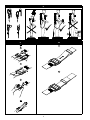
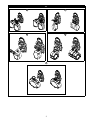
3.6 DONNING AND FITTING THE FULL BODY HARNESS: Figure 13 illustrates donning and fi tting of the Full Body Harness.
Prior to each use, inspect the harness per the checklist on the “Inspection and Maintenance Log (Table 1)”. To don and fi t
the harness:
Procedures for buckling and adjusting the straps on you Harness will vary with the harness model. See Sections 3.3 thru 3.4 and
Figures 9 thru 10 for details.
1. Lift up and hold the harness by the back Dorsal D-Ring on the Easy-Link System. Ensure the straps are not twisted.
2. Grasp the Shoulder Straps and slip the harness onto one arm. The Dorsal D-Ring will be located on your back side.
Ensure that the straps are not tangled and hang freely. Slip your free arm into the harness and position the Shoulder
Straps on top of your shoulders. The Chest Strap and Chest Buckle will be positioned on the front side when worn
properly.
3. Reach between your legs and grasp the Leg Strap on your right side. Bring the strap up between your legs; buckle to
the mating receptor on you right hip, and adjust the Leg Strap for a snug comfortable fi t (see Section 3.3 for buckle
operation). When properly adjusted, tuck the loose end of the Leg Strap under the Strap Keeper.
Repeat this process to buckle and adjust the left Leg Strap.
4. Adjust and buckle the Tongue Buckle Waist Belt (see Section 3.3 for Tongue Buckle operation).

14
5. Buckle and adjust the Chest Strap (see Section 3.3 for buckle operation). The Chest Strap should be 6 in. (15 cm)
down from the to of your shoulders. When properly adjusted, tuck the loose end of the Chest Strap under the Strap
Keeper.
6. Adjust the Shoulder Straps for a Snug Fit with the Revolver Torso Adjusters (see Section 3.4 for Torso Adjuster
operation). Left and right sides of Shoulder Straps should be adjusted to the same length and the Chest Strap should
be centered on your lower chest, 6 in. (15 cm) down from the shoulders. The back Dorsal D-Ring should be centered
between your Shoulder Blades. The front Sternal D-Ring, if present, should be located laterally within 2 in. (51 mm)
of the vertical centerline of the harness (see Section 3.6 for Store-Away D-Ring adjustment).
3.7 USE OF FALL ARREST D-RING OR ATTACHMENT ELEMENT: For Fall Arrest applications connect to the Dorsal D-ring
or attachment element on your back, between your shoulder blades. Side
D-rings, if present, are for Positioning or
Restraint applications only. Shoulder D-rings are for Rescue or Retrieval applications only. The front Sternal D-ring is for
Ladder Climbing or Positioning. D-rings on a Suspension Seat are for Suspension or Positioning applications only. (See
Section 1.1.).
3.8 MAKING CONNECTIONS: When using a hook to connect to an anchorage or when coupling components of the system
together, ensure roll-out cannot occur. Roll-out occurs when interference between the hook and mating connector causes
the hook gate to unintentionally open and release. Self-locking snap hooks and carabiners should be used to reduce the
possibility of roll-out. Do not use hooks or connectors that will not completely close over the attachment object. See
subsystem manufacturer’s instructions for more information on making connections.
3.9 CONNECTING SYSTEM COMPONENTS: After fi tting the Harness the user may then connect to other system
components. Follow the guidelines in Section 2 and the manufacturer’s instructions included with the component.
4.0 INSPECTION
4.1 RFID TAG: The Radio Frequency Identifi cation (RFID) tag on the Harness (see Figure 12) can be used in conjunction with
a handheld reading device and the web based portal to simplify inspection and inventory control and provide records for
your fall protection equipment.
4.2 INSPECTION FREQUENCY: The Full Body Harness must be inspected at the intervals defi ned in Section 2.2. Inspection
procedures are described on the “Inspection and Maintenance Log” (Table 1).
4.3 DEFECTS: If inspection reveals a defective condition, remove unit from service immediately and destroy.
4.4 PRODUCT LIFE: The functional life of Harnesses is determined by work conditions and maintenance. As long as the
product passes inspection criteria, it may remain in service.
5.0 MAINTENANCE, SERVICING, STORAGE
5.1 CLEANING INSTRUCTIONS: Clean the Full Body Harness as follows:
1. Spot clean the harness with water and a mild soap solution.
Use a bleach-free detergent when washing the harness and pads. Fabric softener or dryer sheets SHOULD NOT be used when
laundering and drying the harness and pads.
2. Water temperature for wash and rinse must not exceed 160° F (70° C).
3. The harness and pads may be air dried or tumble dried on low heat not exceeding 200° F (90° C).
More information on cleaning is available from 3M. If you have questions concerning the condition of your harness, or have any
doubt about putting it into service, contact 3M.
5.2 AUTHORIZED SERVICE: Additional maintenance and servicing procedures must be completed by a factory authorized
service center. Authorization must be in writing. Do not attempt to disassemble the unit.
5.3 STORAGE AND TRANSPORT: Store and transport the Full Body Harness in a cool, dry, clean environment out of direct
sunlight. Avoid areas where chemical vapors may exist. Thoroughly inspect the harness after extended storage.
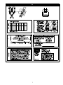
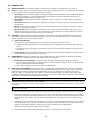
6.0 LABELING:
Figure 14 illustrates product labels and their location on the Full Body Harness. All labeling must be present and fully
legible.

15
Table 1 – Inspection and Maintenance Log
Serial Number(s): Date Purchased:
Model Number: Date of First Use:
Inspection Date: Inspected By:
Component: Inspection: (See Section 2.2 for Inspection Frequency) User Competent
Person
Harness Hardware
(Diagram 1)
Inspect harness hardware including buckles, adjusters, D-rings, Easy-Link, loop keepers, lanyard parking,
etc. These items must not be damaged, broken, or distorted, and must be free of sharp edges, burrs,
cracks, worn parts, or corrosion. PVC coated hardware must be free of cuts, rips, tears, holes, etc. in the
coating to ensure non-conductivity. Ensure buckles and adjusters work smoothly.
Webbing & Stitching
(Diagram 2)
Inspect webbing; material must be free of frayed, cut, or broken fi bers. Check for tears, abrasions, mold,
burns, or discoloration. Inspect stitching; Check for pulled or cut stitches. Broken stitches may be an
indication that the harness has been impact loaded and must be removed from service.
Stitched Impact Indicators
(Diagram 3)
The Stitched Impact Indicators are sections of webbing lapped back on themselves and secured with
a specifi c stitch pattern. The stitch pattern is designed to release when the harness arrests a fall or is
exposed to equivalent force. If an Impact Indicator has been activated (indicated), the harness
must be removed from service and destroyed.
Labels All labels should be present and fully legible. See Figure 14.
System & Subsystem
Components
Inspect each system component or subsystem according to the manufacturer’s instructions.
Diagram 1 – Hardware
Diagram 2 – Webbing
Cut
Frayed
Heavily
Soiled
Welding
Burns
Diagram 3 – Impact
Indicator
Good
Indicated
Corrective Action/Maintenance: Approved By:
Date:
Corrective Action/Maintenance: Approved By:
Date:
Corrective Action/Maintenance: Approved By:
Date:
Corrective Action/Maintenance: Approved By:
Date:
Corrective Action/Maintenance: Approved By:
Date:
Corrective Action/Maintenance: Approved By:
Date:
Corrective Action/Maintenance: Approved By:
Date:
Corrective Action/Maintenance: Approved By:
Date:
Corrective Action/Maintenance: Approved By:
Date:


i
ANSI/ASSE Z359.11-2014 American National Standard
Annex A
ANSI/ASSEE Z359 Requirements for
Proper Use and Maintenance of Full Body Harnesses
NOTE: These are general requirements and information provided by ANSI/ASSE Z359, the Manufacturer of this
equipment may impose more stringent restrictions on the use of the products they manufacture, see the Manufacturer’s
instructions.
1. It is essential that the users of this type of equipment receive proper training and instruction, including detailed
procedures for the safe use of such equipment in their work application. ANSI/ASSE Z359.2, Minimum Requirements for
a Comprehensive Managed Fall Protection Program, establishes guidelines and requirements for an employer’s managed
fall protection program, including policies, duties and training; fall protection procedures; eliminating and controlling fall
hazards; rescue procedures; incident investigations; and evaluating program effectiveness.
2. Correct fi t of a Full Body Harness is essential to proper performance. Users must be trained to select the size and maintain
the fi t of their Full Body Harness.
3. Users must follow manufacturer’s instructions for proper fi t and sizing, paying particular attention to ensure that buckles are
connected and aligned correctly, leg straps and shoulder straps are kept snug at all times, chest straps are located in the
middle chest area and leg straps are positioned and snug to avoid contact with the genitalia should a fall occur.
4. Full Body Harnesses which meet ANSI/ASSE Z359.11 are intended to be used with other components of a Personal fall
Arrest system that limit maximum arrest forces to 1800 pounds (8 kn) or less.
5. Suspension intolerance, also called suspension trauma or orthostatic intolerance, is a serious condition that can be
controlled with good harness design, prompt rescue and post fall suspension relief devices. A conscious user may deploy a
suspension relief device allowing the user to remove tension from around the legs, freeing blood fl ow, which can delay the
onset of suspension intolerance. An attachment element extender is not intended to be attached directly to an anchorage
or anchorage connector for fall arrest. An energy absorber must be used to limit maximum arrest forces to 1800 pounds (8
kn). the length of the attachment element extender may affect free fall distances and free fall clearance calculations.
6. Full Body Harness (FBH) Stretch, the amount the FBH component of a personal fall arrest system will stretch and deform
during a fall, can contribute to the overall elongation of the system in stopping a fall. it is important to include the increase
in fall distance created by FBH Stretch, as well as the FBH connector length, the settling of the user’s body in the FBH and
all other contributing factors when calculating total clearance required for a particular fall arrest system.
7. When not in use, unused lanyard legs that are still attached to a Full Body Harness D-Ring should not be attached to a work
positioning element or any other structural element on the Full Body Harness unless deemed acceptable by the competent
person and manufacturer of the lanyard. this is especially important when using some types of “y” style lanyards, as some
load may be transmitted to the user through the unused lanyard leg if it is not able to release from the harness. the lanyard
parking attachment is generally located in the sternal area to help reduce tripping and entanglement hazards.
8. Loose ends of straps can get caught in machinery or cause accidental disengagement of an adjuster. All Full Body Harnesses
shall include keepers or other components which serve to control the loose ends of straps.
9. Due to the nature of soft loop connections, it is recommended that soft loop attachments only be used to connect with other
soft loops or carabiners. Snaphooks should not be used unless approved for the application by the manufacturer.
Sections 10-16 provide additional information concerning the location and use of various attachments
that may be provided on this FBH.
10. Dorsal – the dorsal attachment element shall be used as the primary fall arrest attachment, unless the application allows
the use of an alternate attachment. the dorsal attachment may also be used for travel restraint or rescue. When supported
by the dorsal attachment during a fall, the design of the Full Body Harness shall direct load through the shoulder straps
supporting the user, and around the thighs. Supporting the user, post fall, by the dorsal attachment will result in an upright
body position with a slight lean to the front with some slight pressure to the lower chest. considerations should be made
when choosing a sliding versus fi xed dorsal attachment element. Sliding dorsal attachments are generally easier to adjust to
different user sizes, and allow a more vertical rest position post fall, but can increase FBH Stretch.
11. Sternal – the sternal attachment may be used as an alternative fall arrest attachment in applications where the dorsal
attachment is determined to be inappropriate by a competent person, and where there is no chance to fall in a direction
other than feet fi rst. Accepted practical uses for a sternal attachment include, but are not limited to, ladder climbing with a
guided type fall arrester, ladder climbing with an overhead self-retracting lifeline for fall arrest, work positioning and rope
access. the sternal attachment may also be used for travel restraint or rescue.
When supported by the sternal attachment during a fall, the design of the Full Body Harness shall direct load through
the shoulder straps supporting the user, and around the thighs. Supporting the user, post fall, by the sternal attachment
will result in roughly a sitting or cradled body position with weight concentrated on the thighs, buttocks and lower back.
Supporting the user during work positioning by this sternal attachment will result in an approximate upright body position.
if the sternal attachment is used for fall arrest, the competent person evaluating the application should take measures to
ensure that a fall can only occur feet fi rst. This may include limiting the allowable free fall distance. it may be possible for a
sternal attachment incorporated into an adjustable style chest strap to cause the chest strap to slide up and possibly choke
the user during a fall, extraction, suspension, etc. The competent person should consider Full Body Harness models with a
fi xed sternal attachment for these applications.

ii
ANSI/ASSE Z359.11-2014 American National Standard
Annex A
ANSI/ASSEE Z359 Requirements for
Proper Use and Maintenance of Full Body Harnesses
12. Frontal – the frontal attachment serves as a ladder climbing connection for guided type fall arresters where there is no
chance to fall in a direction other than feet fi rst, or may be used for work positioning. Supporting the user, post fall or during
work positioning, by the frontal attachment will result in a sitting body position, with the upper torso upright, with weight
concentrated on the thighs and buttocks. When supported by the frontal attachment the design of the Full Body Harness
shall direct load directly around the thighs and under the buttocks by means of the sub-pelvic strap.
if the frontal attachment is used for fall arrest, the competent person evaluating the application should take measures to
ensure that a fall can only occur feet fi rst. This may include limiting the allowable free fall distance.
13. Shoulder – the shoulder attachment elements shall be used as a pair, and are an acceptable attachment for rescue and
entry/retrieval. the shoulder attachment elements shall not be used for fall arrest. it is recommended that the shoulder
attachment elements be used in conjunction with a yoke which incorporates a spreader element to keep the Full Body
Harness shoulder straps separate.
14. Waist, Rear – the waist, rear attachment shall be used solely for travel restraint. the waist, rear attachment element shall
not be used for fall arrest. Under no circumstances is it acceptable to use the waist, rear attachment for purposes other than
travel restraint. the waist, rear attachment shall only be subjected to minimal loading through the waist of the user, and
shall never be used to support the full weight of the user.
15. Hip – the hip attachment elements shall be used as a pair, and shall be used solely for work positioning. the hip attachment
elements shall not be used for fall arrest. Hip attachments are often used for work positioning by arborists, utility workers
climbing poles and construction workers tying rebar and climbing on form walls. Users are cautioned against using the hip
attachment elements (or any other rigid point on the Full Body Harness) to store the unused end of a fall arrest lanyard, as
this may cause a tripping hazard, or, in the case multiple leg lanyards, could cause adverse loading to the Full Body Harness
and the wearer through the unused portion of the lanyard.
16. Suspension Seat – the suspension seat attachment elements shall be used as a pair, and shall be used solely for work
positioning. the suspension seat attachment elements shall not be used for fall arrest. Suspension seat attachments are
often used for prolonged work activities where the user is suspended, allowing the user to sit on the suspension seat formed
between the two attachment elements. An example of this use would be window washers on large buildings.
User Inspection, Maintenance, and Storage of Equipment
Users of personal fall arrest systems shall, at a minimum, comply with all manufacturer instructions regarding the inspection,
maintenance and storage of the equipment. the user’s organization shall retain the manufacturer’s instructions and make them
readily available to all users. See ANSI/ASSE Z359.2, Minimum Requirements for a Comprehensive Managed Fall Protection
Program, regarding user inspection, maintenance and storage of equipment.
1. In addition to the inspection requirements set forth in the manufacturer’s instructions, the equipment shall be inspected by
the user before each use and, additionally, by a competent person, other than the user, at interval of no more than one year
for:
• Absence or illegibility of markings.
• Absence of any elements affecting the equipment form, fi t or function.
• Evidence of defects in, or damage to, hardware elements including cracks, sharp edges, deformation, corrosion,
chemical attack, excessive heating, alteration and excessive wear.
• Evidence of defects in or damage to strap or ropes including fraying, unsplicing, unlaying, kinking, knotting, roping,
broken or pulled stitches, excessive elongation, chemical attack, excessive soiling, abrasion, alteration, needed or
excessive lubrication, excessive aging and excessive wear.
2. Inspection criteria for the equipment shall be set by the user’s organization. Such criteria for the equipment shall equal or
exceed the criteria established by this standard or the manufacturer’s instructions, whichever is greater.
3. When inspection reveals defects in, damage to, or inadequate maintenance of equipment, the equipment shall be
permanently removed from service or undergo adequate corrective maintenance, by the original equipment manufacturer or
their designate, before return to service.
Maintenance and Storage
1. Maintenance and storage of equipment shall be conducted by the user’s organization in accordance with the manufacturer’s
instructions. Unique issues, which may arise due to conditions of use, shall be addressed with the manufacturer.
2. Equipment which is in need of, or scheduled for, maintenance shall be tagged as unusable and removed from service.
3. Equipment shall be stored in a manner as to preclude damage from environmental factors such as temperature, light, UV,
excessive moisture, oil, chemicals and their vapors or other degrading elements.

The follow models also apply to this instruction:
1100160
1100161
1100162
1100163
1100164
1100170
1100171
1100172
1100173
1100234
1100235
1100236
1100237
1100238
1100239
1100240
1100241
1100264
1100300
1100301
1100302
1100303
1100304
1100305
1100306
1100307
1100308
1100375
1100376
1100378
1100445
1100446
1100451
1100452
1100453
1100454
1100455
1100456
1100457
1100458
1100459
1100460
1100525
1100526
1100527
1100528
1100529
1100530
1100531
1100532
1100533
1100534
1100535
1100536
1100537
1100538
1100539
1100545
1100546
1100547
1100548
1100549
1100580
1100581
1100582
1100583
1100590
1100591
1100592
1100593
1100594
1100595
1100596
1100640
1100641
1100642
1100685
1100686
1100687
1100688
1100689
1100692
1100694
1100730
1100730H
1100731
1100731H
1100732
1100732H
1100733
1100733H
1100734
1100734H
1100735
1100735H
1100736
1100736H
1100737
1100737H
1100738
1100738H
1100739
1100739H
1100740
1100741
1100742
1100743
1100790
1100791
1100792
1100793
1100825
1100826
1100827
1100828
1100829
1100940
1100940H
1100941
1100941H
1100942
1100943
1100944
1100970
1100971
1100972
1100973
1100990
1100991
1100992
1100993
1100995
1100996
1100997
1101093
1101094
1101095
1101096
1101097
1101098
1101099
1101190
1101191
1101192
1101193
1101194
1101195
1101196
1101197
1101198
1101361
1101362
1101363
1101364
1101365
1101366
1101367
1101368
1101369
1101370
1101371
1101372
1101373
1101374
1101411
1101412
1101412H
1101413
1101414
1101414H
1101449
1101485
1101486
1101487
1101488
1101489
1101490
1101491
1101492
1101493
1101495
1101496
1101497
1101498
1101590
1101591
1101592
1101593
1101594
1101595
1101596
1101597
1101598
1101615
1101616
1101617
1101618
1101619
1101620
1101621
1101710
1101711
1101712
1101720
1101735
1101736
1101737
1101738
1101740
1101741
1101763
1101763H
1101764
1101764H
1101765
1101765H
1101766
1101766H
1101767
1101767H
1101768
1101768H
1101769
1101769H
1101770
1101770H
1101771
1101771H
1101772
1101772H
1101773
1101773H
1101774
1101883
1101884
1101885
1101886
1101887
1101915
1101916
1101940
1101941
1101942
1101943
1101990
1101991
1101992
1101993
1101994
1101995
1101996
1101997
1102011
1102012
1102013
1102014
1102015
1102144
1102145
1102146
1102147
1102148
1102149
1102181
1102182
1102183
1102184
1102185
1102286
1102306
1102307
1102340
1102341
1102342
1102343
1102346
1102347
1102384
1102385
1102386
1102387
1102388
1102389
1102393
1102440
1102441
1102442
1102443
1102444
1102457
1102458
1102459
1102460
1102461
1102462
1102463
1102464
1102465
1102605
1102606
1102607
1102608
1102609
1102615
1102616
1102617
1102618
1102619
1102660
1102661
1102665
1102666
1102667
1102668
1102669
1102685
1102686
1102687
1102688
1102729
1102730
1102731
1102732
1102740
1102741
1102742
1102743
1102754
1102829
1102830
1102831
1102832
1102833
1102840
1102841
1102842
1102843
1102844
1102860
1102861
1102862
1102863
1102864
1102890
1102891
1102892
1102893
1102894
1102915
1102944
1103039
1103040
1103041
1103042
1103043
1103044
1103054H
1103055H
1103056
1103056H
1103057H
1103058H
1103065
1103066
1103067
1103068
1103080
1103081
1103082
1103083
1103090
1103091
1103092
1103093
1103910
1103911
1103912
1103913
1106093
1106094
1106095
1106096
1107303
1107304
1107880H
1107881H
1107882H
1107883H
1107884H
1107885H
1107886H
1107887H
1107888H
1107889H
1107975
1107976
1107976
1107977
1107977A
1107981
1107982
1107983
1107985
1107986
1107987
1107988
1107989
1107990
1107991
1107992
1107993
1107994
1107995
1107996
1107997
1107998
1107999
1108158
1108498
1108499
1108500
1108500H
1108501
1108501H
1108502
1108502H
1108503
1108504
1108505
1108506
1108507
1108507H
1108508
1108508H
1108509
1108510
1108511
1108512
1108513
1108514
1108515
1108516
1108517
1108518
1108519
1108520
1108521
1108522
1108523
1108524
1108525
1108525H
1108526
1108526H
1108527
1108527H
1108531
1108531H
1108532
1108532H
1108533
1108533H
1108535
1108536
1108537
1108538
1108543
1108550
1108551
1108552
1108553
1108575
1108576
1108577
1108581
1108582
1108583
1108587
1108588
1108600
1108601
1108602
1108604
1108605
1108606
1108607
1108608
1108609
1108610
1108611
1108612
1108613
1108614
1108615
1108616
1108617
1108618
1108619
1108620
1108621
1108622
1108623
1108624
1108650
1108651
1108652
1108653
1108656
1108657
1108658
1108664
1108675
1108676
1108677
1108681
1108682
1108683
1108700
1108701
1108702
1108703
1108704
1108705
1108706
1108707
1108708
1108709
1108716
1108725
1108726
1108727
1108728
1108729
1108750
1108751
1108752
1108753
1108754
1108755
1108900
1108901
1108902
1108903
1108975
1108976
1108977
1108978
1108979
1108980
1108987H
1108988H
1108989H
1108990H
1108991H
1108995
1108996
1108997
1108998
1108999
1109225
1109226
1109227
1109228
1109229
1109230
1109355
1109356
1109357
1109358
1109359
1109375
1109376
1109377
1109378
1109700
1109701
1109702
1109703
1109725
1109726
1109727
1109728
1109729
1109750
1109751
1109752
1109753
1109754
1109756
1109759
1109760
1109761
1109762
1109763
1109764
1109765
1109766
1109767
1109768
1109769
1109770
1109771
1109772
1109773
1109775
1109776
1109777
1109778
1109779
1109800
1109801
1109802
1109803
1109804
1109805
1109806
1109807
1109808
1109809
1109810
1109811
1109812
1109813
1109814
1109815
1109816
1109817
1109818
1109827
1109925
1109926
1109927
1109928
1109929
1110000
1110001
1110075
1110076
1110077
1110078
1110079
1110100
1110101
1110102
1110103
1110104
1110105
1110106
1110107
1110108
1110109
1110110
1110111
1110112
1110113
1110113H
1110114
1110114H
1110115
1110115H
1110116
1110116H
1110117
1110117H
1110125
1110126
1110127
1110128
1110129
1110150
1110151
1110152
1110152H
1110153
1110154
1110155
1110156
1110157
1110158
1110159
1110160
1110161
1110162
1110163
1110164
1110165
1110166
1110167
1110168
1110169
1110169H
1110170
1110170H
1110171
1110171H
1110172
1110172H
1110174
1110175
1110176
1110177
1110178
1110179
1110180
1110200
1110201
1110202
1110203
1110204
1110205
1110206
1110207
1110208
1110209
1110221
1110221H
1110222
1110222H
1110223
1110223H
1110224
1110224H
1110225
1110226
1110227
1110228
1110229
1110230
1110231
1110232
1110233
1110234
1110235
1110250
1110251
1110252
1110253
1110254
1110275
1110276
1110277
1110278
1110279
1110300
1110301
1110302
1110303
1110304
1110305
1110325
1110326
1110327
1110328
1110350
1110351
1110352
1110353
1110354
1110355
1110375
1110376
1110377
1110378
1110379
1110400
1110401
1110402
1110403
1110404
1110427
1110475
1110476
1110477
1110478
1110479
1110480
1110481
1110482
1110483
1110484
1110500
1110501
1110502
1110503
1110504
1110525
1110526
1110527
1110528
1110529
1110550
1110551
1110552
1110553
1110560
1110561
1110562
1110563
1110840
1110841
1110842
1110843
1110844
1110845
1110846
1110847
1110848
1110849
1110850
1110851
1110852
1110853
1110854
1110855
1110856
1110857
1110858
1110859
1110860
1110861
1110862
1110870
1110871
1110872
1110873
1110880
1110881
1110882
1110883
1110884
1110885
1110886
1110887
1110888
1110889
1110890
1110891
1110892
1110893
1110894
1110900
1110901
1110902
1110903
1110904
1110910
1110911
1110912
1110913
1110914
1110960
1110963
1110964
1110970
1110971
1110982
1110983
1111010
1111011
1111012
1111013
1111014
1111015
1111016
1111017
1111018
1111019
1111020
1111021
1111022
1111075
1111076
1111077
1111078
1111079
1111085
1111086
1111087
1111088
1111089
1111090
1111091
1111092
1111093
1111094
1111095
1111096
1111097
1111098
1111150
1111151
1111152
1111153
1111154
1111155
1111156
1111157
1111158
1111300
1111301
1111302
1111303
1111307
1111380
1111381
1111382
1111383
1111384
1111400
1111401
1111402
1111403
1111404
1111405
1111406
1111407
1111408
1111409
1111410
1111425
1111426
1111427
1111428
1111429
1111452
1111475
1111476
1111477
1111478
1111479
1111525
1111526
1111527
1111528
1111529
1111530
1111550
1111551
1111552
1111553
1111554
1111600
1111601
1111602
1111603
1111640
1111641
1111642
1111643
1111644
1111645H
1111700
1111701
1111702
1111703
1111704
1111800
1111801
1111802
1111803
1111804
1113790
1113791
1113792
1113793
1114062
1114063
1114064
1114065
1114066

ISO
9001
USA
3833 SALA Way
Red Wing, MN 55066-5005
Toll Free: 800.328.6146
Phone: 651.388.8282
Fax: 651.388.5065
Brazil
Rua Anne Frank, 2621
Boqueirão Curitiba PR
81650-020
Brazil
Phone: 0800-942-2300
Mexico
Calle Norte 35, 895-E
Col. Industrial Vallejo
C.P. 02300 Azcapotzalco
Mexico D.F.
Phone: (55) 57194820
Colombia
Compañía Latinoamericana de Seguridad S.A.S.
Carrera 106 #15-25 Interior 105 Manzana 15
Zona Franca - Bogotá, Colombia
Phone: 57 1 6014777
Canada
260 Export Boulevard
Mississauga, ON L5S 1Y9
Phone: 905.795.9333
Toll-Free: 800.387.7484
Fax: 888.387.7484
EMEA (Europe, Middle East, Africa)
EMEA Headquarters:
5a Merse Road
North Moons Moat
Redditch, Worcestershire
B98 9HL UK
Phone: + 44 (0)1527 548 000
Fax: + 44 (0)1527 591 000
France:
Le Broc Center
Z.I. 1re Avenue - BP15
06511 Carros Le Broc Cedex
France
Phone: + 33 04 97 10 00 10
Fax: + 33 04 93 08 79 70
Australia & New Zealand
95 Derby Street
Silverwater
Sydney NSW 2128
Australia
Phone: +(61) 2 8753 7600
Toll-Free : 1800 245 002 (AUS)
Toll-Free : 0800 212 505 (NZ)
Fax: +(61) 2 8753 7603
Asia
Singapore:
1 Yishun Avenue 7
Singapore 768923
Phone: +65-6450 8888
Fax: +65-6552 2113
TotalF[email protected]
Shanghai:
19/F, L’Avenue, No.99 Xian Xia Rd
Shanghai 200051, P R China
Phone: +86 21 62539050
Fax: +86 21 62539060
Korea:
3M Koread Ltd
20F, 82, Uisadang-daero,
Yeongdeungpo-gu, Seoul
Phone: +82-80-033-4114
Fax: +82-2-3771-4271
TotalF[email protected]
Japan:
3M Japan Ltd
6-7-29, Kitashinagawa, Shinagawa-ku, Tokyo
Phone: +81-570-011-321
Fax: +81-3-6409-5818
3M.com/FallProtection
U.S. PRODUCT WARRANTY, LIMITED REMEDY
AND LIMITATION OF LIABILITY
WARRANTY: THE FOLLOWING IS MADE IN LIEU OF ALL WARRANTIES OR CONDITIONS, EXPRESS
OR IMPLIED, INCLUDING THE IMPLIED WARRANTIES OR CONDITIONS OF MERCHANTABILITY OR
FITNESS FOR A PARTICULAR PURPOSE.
Unless otherwise provided by applicable law, 3M fall protection products are warranted against factory
defects in workmanship and materials for a period of one year from the date of installation or fi rst use
by the original owner.
LIMITED REMEDY: Upon written notice to 3M, 3M will repair or replace any product determined by
3M to have a factory defect in workmanship or materials. 3M reserves the right to require product be
returned to its facility for evaluation of warranty claims. This warranty does not cover product damage
due to wear, abuse, misuse, damage in transit, failure to maintain the product or other damage beyond
3M’s control. 3M will be the sole judge of product condition and warranty options.
This warranty applies only to the original purchaser and is the only warranty applicable to 3M’s fall
protection products. Please contact 3M’s customer service department at 800-328-6146 or via email at
3MF[email protected] for assistance.
LIMITATION OF LIABILITY: TO THE EXTENT PERMITTED BY APPLICABLE LAW, 3M IS NOT
LIABLE FOR ANY INDIRECT, INCIDENTAL, SPECIAL OR CONSEQUENTIAL DAMAGES INCLUDING,
BUT NOT LIMITED TO LOSS OF PROFITS, IN ANY WAY RELATED TO THE PRODUCTS REGARDLESS
OF THE LEGAL THEORY ASSERTED.
-
 1
1
-
 2
2
-
 3
3
-
 4
4
-
 5
5
-
 6
6
-
 7
7
-
 8
8
-
 9
9
-
 10
10
-
 11
11
-
 12
12
-
 13
13
-
 14
14
-
 15
15
-
 16
16
-
 17
17
-
 18
18
-
 19
19
-
 20
20


3M DBI-SALA® ExoFit™ XP Vest-Style Climbing Harness 1110204, 2X-Large, 1 EA Operating instructions
- Type
- Operating instructions
Ask a question and I''ll find the answer in the document
Finding information in a document is now easier with AI
Related papers
-
3M Protecta® Comfort Vest-Style Positioning/Climbing Harness 1161444, Black, X-Large, 1 EA/Case Operating instructions
-
3M DBI-SALA® Suspension Trauma Safety Straps, Fire Resistant 9505712, 1 EA Operating instructions
-
3M DBI-SALA® ExoFit STRATA™ Vest-Style Climbing Harness 1112508, Grey, Blue, X-Large, 1 EA Operating instructions
-
-
3M DBI-SALA® ExoFit STRATA™ Construction Style Positioning/Climbing and Retrieval Harness 1112549, 2X-Large, 1 EA Operating instructions
-
-
-
3M DBI-SALA® Confined Space Portable Fall Arrest Post 8516996, 1 EA Operating instructions
-
-
3M DBI-SALA® Delta™ Arc Flash Harness, Dorsal/Rescue Web Loops 1110780, Medium, 1 EA Operating instructions
Other documents
-
Honeywell H700 User manual
-
DeWalt D3000 Series User manual
-
-
 KwikSafety KS6602T Thunder 3 D-Ring User manual
-
Werner Full Body Harness Operating instructions
-
Werner H312004 Owner's manual
-
Echo 99944200202 User manual
-
 Ultra-safe 96701S User Instruction Manual
-
Guardian Seraph Construction Harness for Confined Space Operating instructions
-

