Page is loading ...

W415-0865 / B / 05.26.11
1
INSTALLER: LEAVE THIS MANUAL WITH THE APPLIANCE.
CONSUMER: RETAIN THIS MANUAL FOR FUTURE REFERENCE.
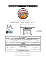
INSTALLATION AND
OPERATING INSTRUCTIONS
1.18B
Wolf Steel Ltd., 24 Napoleon Rd., Barrie, ON, L4M 0G8 Canada /
103 Miller Drive, Crittenden, Kentucky, USA, 41030
Phone (705)721-1212 • Fax (705)722-6031 • www.timberwolffi replaces.com • ask@timberwolffi replaces.com
$10.00
SAFETY INFORMATION
!
WARNING
PLEASE READ ENTIRE MANUAL
BEFORE YOU INSTALL OR USE THIS
PELLET BURNING APPLIANCE.
If the appliance is not properly installed,
a house fi re may result causing personal
injury or loss of life.
- Authorities having jurisdiction (such as
municipal building department, fi re department,
fi re prevention bureau, etc.) should be consulted
before installation to determine the need to obtain
a permit.
- Contact local building or fi re offi cials about
restrictions and installation inspection
requirements in your area.
- This appliance is hot while in operation. Keep
children, clothing and furniture away. Contact may
cause skin burns.
- Do not start a fi re with chemicals or fl uids such
as gasoline, engine oil, etc...
CERTIFIED FOR CANADA AND UNITED STATES USING ANSI/CSA METHODS.
This appliance has been tested to ASTM E 1509, ULC/ORD C1482M-90, ULC S627 AND ULC S628.
TPS35
PELLET STOVE
TPI35
PELLET INSERT

W415-0865 / B / 05.26.11
2
NOTE: Changes, other than editorial, are denoted by a vertical line in the margin.
TABLE OF CONTENTS
1.0 INSTALLATION OVERVIEW 3
1.1 STOVE 3
1.2 INSERT 4
2.0 INTRODUCTION 5
2.1 DIMENSIONS 6
2.1.1 STOVE 6
2.1.2 INSERT (COMPLETE WITH FLASHING) 6
2.2 SPECIFICATIONS 7
2.3 GENERAL INSTRUCTIONS 7
2.4 GENERAL INFORMATION 8
2.4.1 FUEL 8
2.4.2 PELLET SPECIFICATIONS 9
2.4.3 CORN SPECIFICATIONS 9
2.4.4 SAFETY FEATURES 10
2.4.5 EPA COMPLIANCE 10
2.5 RATING PLATE INFORMATION 10
3.0 INSTALLATION PLANNING 11
3.1 INSTALLATION OPTIONS 11
3.2 APPLIANCE PLACEMENT 11
3.3 MINIMUM CLEARANCE TO COMBUSTIBLES 12
3.3.1 STRAIGHT INSTALLATION 12
3.3.2 CORNER INSTALLATION 12
3.4 FLOOR PROTECTION REQUIREMENTS INSTALLATION 13
3.5 OUTSIDE AIR 13
3.6 MOBILE HOME 13
4.0 VENTING 14
4.1 TYPE OF VENT 14
4.2 INSTALLING THE PELLET VENT 14
4.3 VENTING THE PELLET APPLIANCE 14
4.4 PELLET VENT TERMINATION 15
4.5 VENT TERMINAL CLEARANCES 15
4.6 STOVE VENTING INSTALLATION EXAMPLES 16
4.6.1 HORIZONTAL TERMINATION (THROUGH WALL) 16
4.6.2 VERTICAL RISE HORIZONTAL TERMINATION (THROUGH WALL) 16
4.6.3 VERTICAL TERMINATION 17
4.6.4 CLASS A CHIMNEY RETROFIT 17
4.6.5 HEARTH MOUNT INSTALLATION 18
4.7 INSERT VENTING INSTALLATION EXAMPLES 19
4.7.1 TYPICAL EXISTING MASONRY INSTALLATION 19
4.7.2 FACTORY BUILT FIREPLACE 20
5.0 FRAMING (INSERT ONLY) 21
5.1 INSTALLATION INTO A COMBUSTIBLE ENCLOSURE 22
5.2 MINIMUM ENCLOSURE CLEARANCES 23
5.3 MINIMUM CLEARANCE TO COMBUSTIBLES 23
5.4 MINIMUM MANTEL CLEARANCES 24
5.5 ALCOVE INSTALLATION REQUIREMENTS (MINIMUM) 24
6.0 FINISHING 25
6.1 INSTALLING VIEWING DOOR 25
6.2 DOOR HANDLE INSTALLATION 26
6.3 DECORATIVE INSET 26
6.4 FLASHING INSTALLATION 27
7.0 WIRING DIAGRAM 28
8.0 OPERATING INSTRUCTIONS 29
8.1 PROPER PELLET LOADING 29
8.2 PRE-START CHECK 29
8.3 LIGHTING APPLIANCE MANUALLY 29
8.4 LIGHTING INSTRUCTIONS 30
8.5 CONTROLS 30
8.6 CONTROL ADJUSTMENT 31
8.7 INSTALLING A THERMOSTAT 31
8.8 SHUTDOWN INSTRUCTIONS 31
9.0 NORMAL OPERATING SOUNDS 32

W415-0865 / B / 05.26.11
3
1.0 INSTALLATION OVERVIEW
Door, see “FINISHING - INSTALLING
THE VIEWING DOOR” section.
Venting, see “GENERAL VENTING”
and “INSTALLATION” sections.
Floor, see “INSTALLATION PLANNING -
FLOOR PROTECTION REQUIRE-
MENTS” section.
See “OUTSIDE AIR”
section.
Handle, see “DOOR
HANDLE INSTALLATION”
section.
Rating plate, see
“RATING PLATE
INFORMATION”
section.
1.1 STOVE
10.0 MAINTENANCE 33
10.1 DAILY (WHENEVER USING THE APPLIANCE) 33
10.1.1 DISPOSAL OF ASHES 33
10.1.2 INSPECT THE BURN POT 33
10.1.3 CARE OF GLASS 33
10.1.4 CLEANING THE HEAT EXCHANGER TUBES 34
10.1.5 MAKE SURE PELLETS ARE NOT PILING UP 34
10.1.6 CLEANING THE BURN POT 35
10.2 BI-WEEKLY (OR EVERY 10 BAGS OF PELLETS) 35
10.2.1 VACUUM FIREBOX 35
10.3 SEMI-ANNUALLY (OR EVERY TWO TONS OF PELLET) 36
10.3.1 VACUUM HOPPER 36
10.3.2 SOOT AND FLY ASH FORMATION 36
10.3.3 CLEAN THE VERTICAL EXHAUST DUCT 36
10.3.4 CLEAN THE EXHAUST BLOWER 37
10.3.5 CHECK ALL SEALS 37
10.3.6 CLEAN THE VENT 38
10.4 IN THE EVENT OF A JAMMED AUGER 38
11.0 REPLACEMENTS 39
12.0 TROUBLESHOOTING 41
13.0 WARRANTY 44
14.0 SERVICE HISTORY 45

W415-0865 / B / 05.26.11
4
1.2 INSERT
Door, see “FINISHING -
INSTALLING THE VIEW-
ING DOOR” section.
Venting, see “VENTING” and
“INSTALLATION” sections.
Handle, see “DOOR
HANDLE INSTALLATION”
section.
Rating plate, see
“RATING PLATE
INFORMATION”
section.
Flashing, see “FLASHING
INSTALLATION” section.

W415-0865 / B / 05.26.11
5
2.0 INTRODUCTION
3.8B
!
WARNING
• THIS APPLIANCE IS HOT WHEN OPERATED AND CAN CAUSE SEVERE BURNS IF CONTACTED.
• Do not operate appliance before reading and understanding operating instructions. Failure to operate appliance according to
operating instructions could cause fi re or injury. Contact the local building or fi re authority and follow their guidelines. Notify
your insurance company of this appliance as well.
• Never try to repair or replace any part of the appliance unless instructions are given in this manual. All other work should be
done by a trained technician.
• Risk of burns. The appliance should be turned off and cooled before servicing.
• Do not operate without fully assembling all components.
• Do not install damaged, incomplete or substitute components.
• Risk of cuts and abrasions. Wear protective gloves and safety glasses during installation. Sheet metal edges may be sharp.
• Children and adults should be alerted to the hazards of high surface temperature and should stay away to avoid burns or
clothing ignition. Toddlers, young children and others may be susceptible to accidental contact burns. A physical barrier is rec-
ommended if there are at risk individuals in the house. To restrict access to an appliance or stove, install an adjustable safety
gate to keep toddlers, young children and other at risk individuals out of the room and away from hot surfaces.
• Clothing or other fl ammable material should not be placed on or near the appliance.
• Due to high temperatures, the appliance should be located out of traffi c and away from furniture and draperies.
• Ensure you have incorporated adequate safety measure to protect infants/toddlers from touching hot surfaces.
• Even after the appliance is out, the glass and/or screen will remain hot for an extended period of time.
• Check with your local hearth specialty dealer for safety screens and hearth guards to protect children from hot surfaces.
These screens and guards must be fastened to the fl oor.
• Any safety screen or guard removed for servicing must be replaced prior to operating the appliance.
• It is imperative that the control compartments, burners and circulating blower and its passageway in the appliance and venting
system are kept clean. The appliance and its venting system should be inspected before use and at least annually by a quali-
fi ed service person. More frequent cleaning may be required due to excessive lint from carpeting, bedding material, etc. The
appliance area must be kept clear and free from combustible materials, gasoline and other fl ammable vapors and liquids.
• Under no circumstances should this appliance be modifi ed.
• Do not use this appliance if any part has been under water. Immediately call a qualifi ed service technician to inspect the appli-
ance and to replace any part of the control system and any gas control which has been under water.
• Do not operate the appliance with the glass door removed, cracked or broken. Replacement of the glass should be done by a
licensed or qualifi ed service person. The viewing door and ashpan must be closed and latched during operation.
• Do not strike or slam shut the appliance glass door.
• Only doors / optional fronts certifi ed with the unit are to be installed on the appliance.
• Keep the packaging material out of reach of children and dispose of the material in a safe manner. As with all plastic bags,
these are not toys and should be kept away from children and infants.
• If the appliance is not properly installed, a house fi re may result. Do not expose the appliance to the elements (ex. rain, etc.)
and keep the appliance dry at all times. Wet insulation will produce an odour when the appliance is used.
• The chimney must be sound and free of cracks. Clean your chimney a minimum of twice a year and as required.
• The heater is designed and approved for pelletized wood fuel only. Any other type of fuel burned in this heater will void the
warranty and safety listing.
• Do not start a fi re with chemicals or fl uids such as gasoline, engine oil, etc.
• Ashes must be disposed in a metal container with a tight lid and placed on a non-combustible surface well away from the
home or structure.
• Your appliance requires periodic maintenance and cleaning. Failure to maintain your appliance may lead to smoke spillage in
your home.
• The exhaust system must be completely straight and properly installed. It is recommended that the pellet vent joints be sealed
with a minimum 500°F (260°C) silicone sealant. Install according to the vent manufacturer’s instructions.
• Ensure clearances to combustibles are maintained when building a mantel or shelves above the appliance. Elevated
temperatures on the wall or in the air above the appliance can cause melting, discolouration or damage to decorations, a T.V.
or other electronic components.
• During a power outage this appliance will not operate. If a power outage does occur, check the appliance for smoke spillage
and open a window if any smoke spills into the room.
• Keep foreign objects out of the hopper.
• Disconnect the power cord before performing any maintenance. NOTE: Turning the pellet feed to “OFF” does not discon-
nect all power to the heater.
• Do not throw this manual away. This manual has important operating and maintenance instructions that you will need at a
later time. Always follow the instructions in this manual.
• At no point should you use fi rewood or fi relogs in this appliance. The use of which could cause a house fi re.
• This appliance must be connected to a standard 115 V, 50Hz grounded electrical outlet. Do not use an adapter plug or sever
the grounding prong. Do not route the electrical cord underneath, in front of, or over the appliance.
• When installed in a mobile home, the appliance must be bolted to the fl oor, have outside air, and NOT BE INSTALLED IN THE
BEDROOM (per H.U.D. requirements). Check with local building offi cials.
• The exhaust system should be checked and cleaned once a year minimum for any build-up of soot or creosote.
• This heater becomes very hot, you MUST wear heat resistant gloves when cleaning or handling this heater.

W415-0865 / B / 05.26.11
6
2.1 DIMENSIONS
19
11
/16"
30
5
/16"
21
1
/4"
23
1
/2"
24
1
/4"
11
5
/8"
17
"
1
7
/8"
CENTRE LINE
OF AIR INTAKE
7
1
/8"
29
3
/8"
10
5
/8"
8
1
/2" CENTRE LINE
OF AIR INTAKE
5
5
/
8
"
CENTRE LINE
OF EXHAUST
21
1
/4"
38
3
/8"
20
13
/16"
A
*
CENTRE
LINE OF
EXHAUST
CENTER LINE
OF INSERT
25
7
/8"
38
3
/8"
1
1
/4"
B
*
CENTRE LINE
OF AIR INTAKE
CENTRE
LINE OF
EXHAUST
2.1.1 STOVE
2.1.2 INSERT (COMPLETE WITH FLASHING)
* A and B are adjustable, see "SPECIFICATIONS" section.

W415-0865 / B / 05.26.11
7
2.2 SPECIFICATIONS
ALL WIRING SHOULD BE DONE BY A QUALIFIED ELECTRICIAN AND SHALL BE IN COMPLIANCE
WITH LOCAL CODES. IN THE ABSENCE OF LOCAL CODES, USE THE CURRENT CSA C22.1
CANADIAN ELECTRIC CODE (IN CANADA) OR THE ANSI/NFPA NO. 70 NATIONAL ELECTRIC CODE
IN THE UNITED STATES.
DO NOT CONNECT THIS APPLIANCE TO A CHIMNEY FLUE SERVING ANOTHER APPLIANCE. DO
NOT CONNECT TO ANY AIR DISTRIBUTION DUCT OR SYSTEM.
PROVIDE ADEQUATE CLEARANCE FOR SERVICING AND OPERATING THE APPLIANCE.
PROVIDE ADEQUATE VENTILATION.
NEVER OBSTRUCT THE FRONT OPENING OF THE APPLIANCE.
OBJECTS PLACED IN FRONT OF THE APPLIANCE MUST BE KEPT A MINIMUM OF 48” FROM THE
FRONT FACE OF THE APPLIANCE.
!
WARNING
AB
Adjuistable Flashing 11" to 13" 10 1/2" to 12 1/2"
Electrical Rating 115 Volts, 3.6 Amps, 60Hz
Watts During Ignition Sequence 400 (approximately)
Watts During Operation 180 (approximately)
Weight Stove 158 lbs / Insert 140 lbs
Exhaust Collar 3"
Intake Collar 2"
Hopper Capacity 45 Pounds
EPA Exempt
Burn Rate 1.5 to 4.5 (Pounds Per Hour)
BTU/H 12750 to 38250
Approximate Maximum Heating Capacity (in square feet)* 800 to 2000 Sq. Feet
Maximum Burn Time on Low Burn** 30 Hours
* Heating capacity will vary depending on the home's fl oor plan, degree of insulation, and the outside temperature. It is
also affected by the fuel size, quality, and moisture level.
** Small pellets will increase or decrease the stated burn rates and burn times. Differences of plus or minus 20% depend-
ing on fuel quality may occur.
2.3 GENERAL INSTRUCTIONS

W415-0865 / B / 05.26.11
8
2.4 GENERAL INFORMATION
Thank you for purchasing a Wolf Steel Ltd. Pellet Appliance. This appliance is designed for use with Pelletized
Wood Only.
Please read this entire manual before installation and use of this pellet fuel-burning room appliance. Failure to
follow these instructions could result in property damage, bodily injury or even death.
Keep this manual handy for future reference.
This Pellet Appliance, when installed, must be electrically grounded in accordance with the local codes, or in
the absence of local codes, use the current CSA C22.1 Canadian Electrical Code in Canada or the ANSI/NFPA
70 National Electrical Code in the United States.
This appliance will not operate using natural draft or without a power source for the blower systems and fuel
feed system.
The protective wrap on plated parts is best removed when the assembly is at room temperature but this can be
improved if the assembly is warmed, using a hair dryer or similar heat source.
If the appliance is installed directly on carpeting, vinyl tile or other combustible material other than wood
fl ooring, the appliance shall be installed on a metal or wood panel extending the full width and depth.
4.5
2.4.1 FUEL
This appliance is designed to burn wood pellet fuel. In addition, a corn/wood pellet mixture with a maximum
50% corn can be burned. Burning any other fuel, that is not approved for use with this appliance, will void the
warranty.
Important: The corn/wood pellet mixture needs to be mixed evenly before being put into the hopper.

W415-0865 / B / 05.26.11
9
If the fuel does not comply to
this standard the appliance may
not operate as designed.
We recommend the use of pre-
mium grade (1% ash content)
for longer appliance life and less
frequent cleaning.
Fines (fi ne particles) 1% maximum through a 1/8" screen
Bulk Density 40 pound per cubic foot minimum
Size 1/4" to 5/16" diameter, 1/2" - 1 1/2" long maximum
Ash Content 1% maximum (Premium grade)
3% maximum (Standard grade)
Moisture Content 8% maximum
Heat Content Approximately 8200 BTU per pound minimum
2.4.2 PELLET SPECIFICATIONS
P.F.I. PELLET STANDARDS:
Pellet quality is important, please read the following:
Your Wolf Steel Ltd. Pellet Appliance has been designed to burn premium hard or soft wood pellets only. Do
not use any other type of fuel such as fi re logs or fi re starting pellets, as this will void the warranties stated in
this manual.
The performance and heat output of the pellet appliance is directly related to the quality and moisture of the
pellets. Store pellets in a cool dry area to prevent moisture absorption.
64.1
!
WARNING
IT IS IMPORTANT TO SELECT AND USE ONLY PELLETS THAT ARE DRY AND FREE OF DIRT OR ANY
IMPURITIES SUCH AS HIGH SALT CONTENT. DIRTY FUEL WILL ADVERSELY AFFECT THE OPERA-
TION AND PERFORMANCE OF THE APPLIANCE AND WILL VOID THE WARRANTY. THE PELLET
FUEL INSTITUTE (P.F.I.) HAS ESTABLISHED STANDARDS FOR WOOD PELLET MANUFACTURERS.
WE RECOMMEND THE USE OF PELLETS THAT MEET OR EXCEED THESE STANDARDS. ASK YOUR
DEALER FOR A RECOMMENDED PELLET TYPE.
2.4.3 CORN SPECIFICATIONS
Use only clean-shelled corn with a moisture content less than 15% and approximate fuel value of 7,000 BTU/
lb (16,200 kJ/kg). Do not attempt to burn corn with higher moisture content or burn lesser grade fuels. Do not
burn other types of agricultural pellets or by-products (alfalfa, cherry pits, olive pits, nut shells, etc.) as they are
not permitted to be burned in this appliance.
Corn must be clean and free of debris. Never burn corn right from the fi eld. Damage caused by dirty corn is
not covered by the Lifetime Limited Warranty. Ask for screened corn only. Stalk parts, excessive fi nes and
cob remnants will clog the air fl ow holes in the burn plate. Check the corn for foreign objects.
Use only a maximum 50% corn to pellet mixture.

W415-0865 / B / 05.26.11
10
2.4.4 SAFETY FEATURES
2.4.5 EPA COMPLIANCE
This appliance is EPA exempt from Phase II
prerequisites, but complies with Oregon /
Washington emissions requirements.
We suggest that our pellet hearth
products be installed and serviced by
professionals who are certified in the U.S.
by the National Fireplace Institute
®
(NFI)
as NFI Pellet Specialists or who are
certified in Canada by
Wood Energy Technical
Training (WETT).
www.nficertified.org
66.1A
HIGH LIMIT SWITCH: Your appliance is equipped with a high limit switch. In the event that the temperature of
the appliance approaches an unsafe operating temperature, this switch will shut down the pellet feed, which
will eventually shut down the unit. If this happens, it is important to fi nd out why the unit overheated. Contact
your local dealer.
LOW LIMIT SWITCH: This switch will automatically shut down the appliance if the fi re goes out or fails to light
within 15 minutes.
HOPPER DOOR INTERLOCK: Your appliance is equipped with a micro switch in the hopper assembly that
shuts-off the auger when the hopper door is opened. Closing the door switches the auger back on, allowing
pellets to feed again.
VACUUM SWITCH: This switch will sense lack of air fl ow through the appliance and shut down the pellet feed.
This lack of fl ow could be caused by a blocked vent.
POWER FAILURE: In the event of a power failure, the appliance will shut down. Once power is restored, the
appliance will re-start, unless the convection air temperature has gone above the high limit switch setting. If
this happens, contact your local dealer.
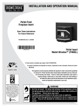
2.5 RATING PLATE INFORMATION
CAUTION: HOT WHILE IN OPERATION. DO NOT TOUCH. KEEP CHILDREN,
CLOTHING AND FURNITURE AWAY. CONTACT MAY CAUSE SKIN BURNS.
U.S. ENVIROMENTAL PROTECTION AGENCY Certified to comply with July 1992 Particulate Emission Standards
MODEL TPS35 LISTED PELLET FUEL BURNING ROOM HEATER TESTED TO:
ASTM E 1509, ULC/ORD C1482-M90, ULC S627
TPS35
Straight Installation Corner Installation
MINIMUM CLEARANCES TO COMBUSTIBLE
SIDE 6”
REAR 3”
CORNER 2”
CEILING 48”
INPUT RATING
MIN 1.5 LB/HR
MAX 4.5 LB/HR
ELECTRICAL RATING
120V 3.6A 60HZ
Floor
Protection
Through
Wall
Installation
3”
6”
- INSTALL AND USE ONLY IN ACCORDANCE WITH THE
MANUFACTURER’S INSTRUCTIONS AND LOCAL
BUILDING CODES.
- MINIMUM CEILING HEIGHT: 7FT (2.13M) HEARTH
EXTENSION / COMBUSTIBLE FLOOR PROTECTION: IF
INSTALLED ON A COMBUSTIBLE FLOOR, UNIT MUST BE
PLACED ON A NON-COMBUSTIBLE FLOOR PROTECTOR
EXTENDING 6” IN FRONT.
- DO NOT CONNECT THIS UNIT TO A CHIMNEY FLUE
SERVING ANOTHER APPLIANCE.
- REPLACE GLASS WITH ONLY CERAMIC GLASS.
DANGER: RISK OF ELECTRICAL SHOCK. DISCONNECT
POWER BEFORE SERVICING UNIT.
- KEEP VIEWING AND ASH REMOVAL DOORS TIGHTLY
CLOSED DURING OPERATION.
- CONTACT LOCAL BUILDING AND FIRE OFFICIALS ABOUT
RESTRICTIONS AND INSTALLATION INSPECTION IN YOUR
LOCAL AREA.
- SUITABLE FOR USE IN MOBILE HOMES WHEN USED WITH
OUTSIDE AIR INSTALLATION KIT.
- REFER TO INSTALLATION INSTRUCTIONS OR LOCAL
BUILDING CODES WHEN PASSING EXHAUST SYSTEM
THROUGH COMBUSTIBLE WALL OR CEILING.
- FUEL: FOR USE WITH PELLET FUEL ONLY.
Floor Protection
6”
2”
Floor Protection
6”
Interior
Vertical
Vent
2”
2”
Tee
WOLF STEEL LTD.
24 NAPOLEON ROAD, BARRIE, ON, L4M 0G8 CANADA
ATTENTION : L'APPAREIL EST CHAUD LORSQU’IL FONCTIONNE. NE PAS
TOUCHER. TENIR LES ENFANTS, LES VÊTEMENTS ET LES MEUBLES À
L’ÉCART. LE CONTACT PEUT CAUSER DES BRÛLURES DE PEAU.
Certifié conforme à la norme d'émanation de particules de juillet 1992 du U.S. ENVIROMENTAL PROTECTION AGENCY
W385-0509 / B
- INSTALLER ET UTILISER CONFORMÉMENT AUX INSTRUCTIONS DU FABRICANT ET
AUX CODES DU BÂTIMENT LOCAUX.
- HAUTEUR DE PLAFOND MINIMALE 7 PI. (2,13 m)
BASE DE PROTECTION/PROTECTION DE PLANCHER COMBUSTIBLE : SI INSTALLÉ
SUR UN PLANCHER COMBUSTIBLE, L’APPAREIL DOIT ÊTRE PLACÉ SUR UNE
PLAQUE PROTECTRICE INCOMBUSTIBLE S’ÉTENDANT SUR 6” À L’AVANT.
- NE PAS RACCORDER CET APPAREIL À LA CHEMINÉE D’UN AUTRE APPAREIL.
- REMPLACER LA VITRE PAR UNE VITRE EN CÉRAMIQUE SEULEMENT.
DANGER : RISQUE DE SECOUSSE ÉLECTRIQUE. DÉBRANCHER L’ALIMENTATION
ÉLECTRIQUE AVANT DE PROCÉDER À L’ENTRETIEN.
- GARDER LA PORTE VITRÉE ET LA PORTE DU TIROIR À CENDRES BIEN FERMÉES
DURANT LE FONCTIONNEMENT.
- CONTACTER LES AUTORITÉS LOCALES DU BÂTIMENT ET DU SERVICE DES
INCENDIES AU SUJET DES RESTRICTIONS ET DES INSPECTIONS D’INSTALLATION
DANS VOTRE RÉGION.
- PEUT ÊTRE INSTALLÉ DANS UNE MAISON MOBILE SI INSTALLÉ CONJOINTEMENT
AVEC UNE PRISE D’AIR EXTÉRIEUR.
- SE RÉFÉRER AUX INSTRUCTIONS D’INSTALLATION OU AUX CODES DU BÂTIMENT
LOCAUX LORSQUE LE SYSTÈME D’ÉVACUATION TRAVERSE UN MUR OU UN
PLAFOND COMBUSTIBLES.
- COMBUSTIBLE : POUR USAGE AVEC DES GRANULES SEULEMENT.
Installation droite
Installation de coin
MODÈLE TPS35 APPAREIL DE CHAUFFAGE AUX GRANULES HOMOLOGUÉ TESTÉ SELON LES
NORMES : ASTM E 1509, ULC/ORD1482-M90, ULC S627
DÉGAGEMENTS MINIMAUX AUX MATÉRIAUX COMBUSTIBLES
CÔTÉ 6”
ARRIÈRE 3”
COIN 2”
PLAFOND 48”
IDÉBIT D’ALIMENTATION
MIN. 1.5 LB/H
MAX. 4.5 LB/H
CARACTÉRISTIQUES ÉLECTRIQUES
120 V 60 Hz
3”
2”
Te e
Interior
Vertical
Vent
DATE CODE / DE DATE
6”
6”
Floor
Protection
6”
6”
Protection de
plancher
Installations
à travers le
mur
Protection de
plancher
Évents à
travers le
mur
Coude
45°
Té
Protection de
plancher
Évents
verticaux
intérieurst
Protection de
plancher
Évents
verticaux
intérieurs
Té
6”
45°
2”
2”
6”
2”
2”
3”
2”
6”
6”
6”
6”
6”
9700539 (WSL)
4001657 (NGZ)
4001658 (NAC)
4001659 (WUSA)
REFERENCE
#16544
Stove rating plate illustrated
For rating plate location, see “INSTALLATION OVERVIEW” section.
This illustration is for reference only. Refer to the rating plate on the appliance for accurate information.
SAMPLE
SAMPLE
S. ENVIROMENTAL PROTECTION AGENCY C. ENVIROMENTAL PROTECT
RNING ROOM HEATERRNING ROOM HEAT
D C1482-M90, ULC S627D C1482-M90, ULC S627
MPLE
S
TPS
Corner Ins
Corner In
EARANCES TO COMBUSTIBLEEARANCES TO COMBUST
6”
3”
NER 2” 2”
ILING 48”LING 48”
P
E
L
L
L
L
L
L
L
E
E
E
E
E
E
E
E
E
E
E
E
E
6”6”
L
L
L
LE
LE
LE
LE
L
LE
LE
LE
L
L
L
L
ON, L4M 0G8 CANADAON, L4M 0G8 CANADA
AUD LORSQU’IL FONCTIONNE. NE PAS AUD LORSQU’IL FONCTIONNE. NE P
LES VÊTEMENTS ET LES MEUBLES À LES VÊTEMENTS ET LES MEUBLES
AUSER DES BRÛLURES DE PEAU.AUSER DES BRÛLURES DE PEAU.
TATIONN
EN FERMÉES
ERVICE DESRVICE D
ONS D’INSTALLATION ONS D’INSTALLAT
STALLÉ CONJOINTEMENT LLÉ CONJOINTEMENT
OU AUX CODES DU BÂTIMENT ODES DU BÂTIMENT
TRAVERSE UN MUR OU UN N MUR OU
RANULES SEULEMENT. ULES SEULEMENT.
Installation droitInstallation droi
MODÈLE TPS35 APPAREIL DE CHAUMODÈLE TPS35 APPAREIL DE
NORMES : ASNORMES : A
AMP
MP
PLE
L
L
L
PL
PL
PL
PL
PL
PL
PL
PL
LE
LE
LE
LE
L
l
nt
PL
PL
PL
PL
PL
PL
PL
PL
L
PL
L
PL
PL
PL
PL
PL
L
PL
L
PL
PL
PL
PL
PL
PL
L
PL
PL
PL
PL
L
PL
PL
PL
PL
L
L
L
PL
PL
PL
PL
PL
PL
PL
PL
PL
PL
PL
PL
L
L
L
L
L
L
PL
L
L
PL
PL
L
L
L
PL
PL
PL
PL
PL
PL
PL
PL
PL
PL
PL
PL
PL
PL
PL
PL
PL
PL
PL
PL
PL
PL
6”6”
Floo
r
Fl
P
r
o
t
ec
ti
o
n
Prot
LE
L
L
L
L
L
L
L
L
L
L
L
L
L
L
L
L
L
L
L
L
Pr
o
t
ec
ti
o
n
de
Protection de
pl
anc
h
er
plancher
Installations
Installations
à
travers le
à travers le
m
u
rmur
AM
M
M
M
M

W415-0865 / B / 05.26.11
11
3.0 INSTALLATION PLANNING
Check with local building offi cials for any permits required for installation of this pellet appliance and notify your
insurance company before proceeding with installation.
Before installing we recommend placing the appliance outside and load 5 pounds of pellets inside the hopper.
Plug the appliance in and let it run on HIGH until the pellets run out. This will cure the paint and burn off most
of the oils on the steel, thereby minimizing any smell inside the home.
68.1
!
WARNING
READ ENTIRE MANUAL BEFORE YOU INSTALL OR USE THIS APPLIANCE. FAILURE TO FOLLOW THE
INSTRUCTIONS MAY RESULT IN PROPERTY DAMAGE, BODILY INJURY OR EVEN DEATH.
USE ONLY WOLF STEEL APPROVED OPTIONAL ACCESSORIES AND REPLACEMENT PARTS WITH
THIS APPLIANCE. USING NON-LISTED ACCESSORIES AND REPLACEMENT PARTS (BLOWERS,
DOORS, LOUVRES, TRIMS, GAS COMPONENTS, VENT COMPONENTS, ETC.) COULD RESULT IN A
SAFETY HAZARD AND WILL VOID THE LIMITED LIFETIME WARRANTY.
3.1 INSTALLATION OPTIONS
Stove model:
To install in a Residential or Mobile Home see "MOBILE HOME INSTALLATION" section. For alcove instal-
lations see "ALCOVE INSTALLATION REQUIREMENTS" section. For horizontal vent or vertical vent see
"VENTING" section. Outside air, see "OUTSIDE AIR" section.
Insert model:
To install as an insert into an existing masonry appliance or factory built appliance see "VENTING" section. To
install into a combustible enclosure, see "INSTALLATION INTO A COMBUSTIBLE ENCLOSURE" section.
Have an authorized dealer install the appliance. If you install the appliance yourself, have your dealer review
your installation plans and/or installation.
Draw out a detailed plan of the installation including dimensions and verify the dimensions with the require-
ments listed in this manual.
You may wish to adjust the appliance position slightly to ensure the vent does not intersect with a framing
member. Appliance must be positioned so that no combustibles are within, or can swing within (e.g. drapes,
doors), 48” of the front of the appliance.
67.1A
3.2 APPLIANCE PLACEMENT

W415-0865 / B / 05.26.11
12
3”
2”
6”
6”
Floor
Protection
6”
Floor
Protection
3”
6”
6”
6”
Floor Protection
6”
2”
2”
6”
45°
Floor Protection
6”
45°
2”
2”
45°
Elbow
6”
3.3 MINIMUM CLEARANCE TO COMBUSTIBLES
Through the Wall Installations complete
with outside air
Interior Vertical Vents
3.3.1 STRAIGHT INSTALLATION
DO NOT INSTALL INTO ANY AREA HAVING LESS THAN 48" (CEILING TO APPLIANCE BOTTOM,
EXCLUDING HEARTH HEIGHT).
!
WARNING
Through the Wall Vents complete with outside air Interior Vertical Vents
NOTE: If interior vertical pellet vent is used, the clearance to the back wall is determined by the up-
ward-turning elbow or "Tee". It will vary in depth depending on the brand of pellet vent used (it is ap-
proximately 5"). Before placing the appliance, connect the elbow or "Tee" and allow for the minimum
3" clearance to the combustible wall.
3.3.2 CORNER INSTALLATION

W415-0865 / B / 05.26.11
13
3.4 FLOOR PROTECTION REQUIREMENTS INSTALLATION
29.4A
Installation into a manufactured home or mobile home should be installed in
accordance with the Manufactured Home Construction and Safety Standard,
Title 24 CFR, Part 3280, in the United States or the Mobile Home Standard,
CAN/CSA Z240 MH Series, in Canada.
The appliance must be grounded to the steel chassis of the mobile home
(Some states do not require this; check with your local building department).
!
WARNING
DO NOT INSTALL IN A SLEEPING ROOM.
THE STRUCTURAL INTEGRITY OF THE MANUFACTURED HOME FLOOR, WALL, AND CEILING ROOF
MUST BE MAINTAINED.
3.5 OUTSIDE AIR
Available from your Authorized Dealer (114KT)
Outside air must not be drawn from an enclosed space (garage, unventilated crawl space).
NOTE: Wolf Steel Ltd. strongly suggests using outside air for all residential installations, especially for
those that are energy effi cient, air-tight homes.
Outside air supply must not be over 15' long.
Outside air vents must be made with 1 3/4" diameter or larger metal or aluminum duct with a metal screen at-
tached to the end to keep out rodents (P.V.C. or other materials may not be used).
The outside air inlet must not be above or within 12" of the chimney termination, must have a rain cap or down-
turned elbow to prevent the water from entering and be located so that it will not become plugged by snow or
other material.
Outside air is required for all combustible built-in enclosure installations.
STOVE
ILLUSTRATED
The appliance must be installed on a non-combustible fl oor protector extending the full depth of the appliance
and extending a minimum 6" in front and on either side (minimum .018" thick - 26 gauge) of the fuel loading
and ash removal openings.
The fl oor protector must extend under and 2" beyond each side and rear of a "Tee" (if used).
NOTE: Floor protection is required for spark and ash shielding, but not for limiting fl oor temperatures
from the radiant heat of the appliance. The appliance was designed and safety tested so that without
any protection, the fl oor would not overheat.
Refer to local building codes for suitable fl oor protection materials.
3.6 MOBILE HOME

W415-0865 / B / 05.26.11
14
4.0 VENTING
4.1 TYPE OF VENT
4.2 INSTALLING THE PELLET VENT
4.3 VENTING THE PELLET APPLIANCE
Must be an approved 3" or 4" diameter Type "L" or "PL" vent, vented to the outside or connect the vent to a
factory built type "A" chimney using an adaptor; and/or stainless steel chimney liner for masonry appliance in-
stallations. Use 4" diameter vent if vent or liner height is over 15' or if installation is over 4,000' above sea level.
Use an approved wall thimble when passing the vent through walls and a ceiling support / fi restop spacer when
passing the vent through ceilings (maintain a 3" clearance to any combustibles).
7.5A
The vent must have a support bracket every 5’ when on
the exterior wall. To achieve optimum performance, keep
vent runs as short as possible, especially on horizontal
installations.
MAXIMUM VENTING: Maximum venting height is 33’.
Maximum horizontal vent run is 10’. Use no more than
180° of elbows (two 90’ elbows, or two 45’ elbows and
one 90’ elbow, etc), excluding the tee and the termination.
VENT INSTALLATION: Termination must exhaust above
the air inlet elevation, and parallel or above the exhaust
output of the pellet appliance. It is recommended that at
least 3’ of vertical pipe be installed to create some natural
draft. This is to help prevent the possibility of smoke or
odour entering the home during the appliance shut down
or in the event of a power outage. Horizontal sections
must have a 1/4” rise every 12” of travel if longer than 3’.
The pellet vent connections must be sealed with HI-Temp
RTV Silicone and screwed together with at least 3 3/8”
long stainless steel screws. Seal each vent section by
injecting a liberal amount of 500°F (260°C) RTV silicone
sealant into the gap. We recommend sealing the outside
of the vent connections to permit easier access when
servicing.
5’
10’
15’
20’
33’
30’
25’
0’
5’
10’
0’
Use 4” diameter
“L” vent if
venting in this
region.
Use 3” or 4”
diameter “L”
vent if venting
in this region.
!
WARNING
PELLET VENT MUST MAINTAIN A MINIMUM 3" CLEARANCE TO ANY COMBUSTIBLE (INSTALL VENT
AT CLEARANCES SPECIFIED BY THE VENT MANUFACTURER).
DO NOT CONNECT THE PELLET VENT TO A VENT OR CHIMNEY SERVING ANY OTHER APPLIANCE
OR HEATER.
DO NOT INSTALL A FLUE DAMPER IN THE EXHAUST VENTING SYSTEM OF THIS UNIT.

W415-0865 / B / 05.26.11
15
4.4 PELLET VENT TERMINATION
The vent termination must have an approved cap (to prevent water from entering) or a 45° downturn.
If the termination is located on a windy side of the house, a shield is recommended to prevent soot from build-
ing up on the side of the house.
Horizontal terminations must protrude 12" from the wall, vertical terminations require a minimum 24" above the
highest point that it penetrates through the roof.
Depending on pellet quality, vent confi guration and air settings, black soot may occur on the terminal wall.
4.5 VENT TERMINAL CLEARANCES
CLEARANCES
A 24” Clearance above grade, veranda porch, deck or balcony. (Including vegetation and mulch)
B
48” Clearance beside or below any windows or doors that open.
12” * Clearance above any window or door that opens.
C 18”
Vertical clearance to ventilated soffi t located above the terminal within a horizontal distance of 2 feet
from the center line of the terminal.
D 0” Clearance to an outside corner wall.
E 3”
Clearance to an inside combustible corner wall or protruding combustible obstructions (vent chase,
etc.)
F 9” Clearance to a non-mechanical air supply inlet to the building or a combustion air inlet to any other appliance.
G 3” Clearance to a mechanical air supply inlet.
H 7’ ** Clearance above a paved sidewalk or paved driveway located on public property.
I 12” ** Clearance under a veranda, porch, deck or balcony.
J 24” Clearance above the roof.
K 2’ Clearance from an adjacent wall including neighbouring buildings.
L
3’ within a
height of 15 feet
above the meter
/ regulator as-
sembly
Clearance to each side of center line extended above natural gas or propane meter / regulator assembly
or mechanical vent.
* Recommended to prevent condensation on windows and thermal breakage
** This is a recommended distance. For additional requirements check local codes.
A
J
D
K
I
H
E
C
B
G
F
E
B
L
12.7A
NOTE: Illustration dimensions are to the center of
the exhaust exit point of the vent.

W415-0865 / B / 05.26.11
16
Floor
Protection
12” Minimum
Outside Air
(Recommended)
6”
Minimum
3” Minimum
Wall
Thimble
11 5/8”
5’ Maximum
Wall Thimble
Outside Air
(Recommended)
3”
2”
Floor
Protection
6”
Minimum
11 5/8”
17”
17”
4.6 STOVE VENTING INSTALLATION EXAMPLES
4.6.1 HORIZONTAL TERMINATION (THROUGH WALL)
4.6.2 VERTICAL RISE HORIZONTAL TERMINATION (THROUGH WALL)

W415-0865 / B / 05.26.11
17
Outside air (Recommended)
(Installation showing inlet of out-
side air in ventilated crawl space)
Ceiling Support
Vent must maintain 3”
clearance to combus-
tibles.
Vertical Cap
Roof Flashing
Storm Collar
Floor Protection
3”
2”
4.6.3 VERTICAL TERMINATION
Class A Chimney
Ceiling Support
Outside air
(Recommended)
(Installation show-
ing inlet of outside
air in ventilated
crawl space)
Vent must maintain
3” clearance to
combustibles.
Roof Flashing
Storm Collar
Floor Protection
3”
2”
Vertical Cap
4.6.4 CLASS A CHIMNEY RETROFIT

W415-0865 / B / 05.26.11
18
Floor Protection
6”
MIN
Clean-out
tee
Outside Air (Recommended)
Fl
oo
r Pr
o
t
ect
6
M
I
N
R
ec
om
me
nd
ed
)
o
ut
Ou
ts
id
e
Ai
r
(R
Storm Collar
Vertical Cap
S
torm
Co
Chimney Cap
Bring outside air to the stove
Pellet
Liner
Flue Cover
Pellet
Vent
4.6.5 HEARTH MOUNT INSTALLATION

W415-0865 / B / 05.26.11
19
4.7 INSERT VENTING INSTALLATION EXAMPLES
4.7.1 TYPICAL EXISTING MASONRY INSTALLATION
!
WARNING
Prior to installation:
When installing the insert into a masonry fi replace, do not
remove any bricks or masonry. Do not weaken the structure,
or reduce the protection for combustible materials to less then
that required by the National Building Code. Bolted or screwed
together pieces (smoke shelf / defl ectors) may be removed,
but must be able to be re-installed if the appliance is removed.
External trim pieces, which do not affect the operation of the
fi replace, may be removed provided they are available to be re-
installed in event the appliance is removed.
A warning label must be attached to the back wall of the fi replace
stating that “This fi replace has been altered to accommodate a
fi replace insert and must be re-inspected by a qualifi ed person
prior to re-use as a fi replace”.
Non-combustible fl oor protection must cover the fl ooring
underneath, as well as extend a minimum of six inches in front
and to both sides of the appliance.
Clean all ashes out of the inside of the fi replace. Make sure
that the chimney and fi replace are free of cracks, loose mortar,
creosote deposits, blockage or other signs of deterioration.
If necessary, have any repair work done by a qualifi ed
professional before installing the appliance.
A. Remove the fi replace damper or fasten it permanently open.
B. Measure the throat of the fi replace and mark this shape on a piece of 24 gauge sheet metal (fl ue
cover). Cut a hole sized for the pellet liner to lie directly below the fi replace fl ue opening. Allow two
inches of material for a fl ange on all sides and cut to these measurements. Bend down the fl anges. If
you have never done this before, it might be a good idea to make a cardboard pattern and test it fi rst.
Fasten this fl ue cover in position as high as possible with two masonry screws per side through the
fl anges into the fi replace.
C. If you plan on connecting outside air it is recommended to do so at this time.
D. Install fl oor protection if necessary.
E. Connect the pellet vent with a clean out tee to the back of the insert. Refer to manufacturer’s
installation instructions to see “REAR TO TOP VENT CONVERSION INSTRUCTIONS” section and th
e
“GENERAL VENTING” section.
F. Run a liner down the chimney and connect to tee.
G. Position the insert in it’s fi nal location.
H. Pull the excess length of liner out through the top of the chimney. Trim the excess liner, install the cap
and cap the chimney.
DO NOT REMOVE BRICKS OR MORTAR FROM THE FIREPLACE.
Storm Collar
Vertical Cap
Outside Air
(Recommended)
o
rm
C
olla
r
S
t
o
rtical
Cap
Ver
Cover Plate
Flue
Cover
Pellet
Liner
62.3A

W415-0865 / B / 05.26.11
20
4.7.2 FACTORY BUILT FIREPLACE
Prior to installation:
Do not weaken the structure, or reduce the protection for
combustible materials to less then that required by the National
Building Code. Bolted or screwed together pieces (smoke shelf /
defl ectors) may be removed, but must be able to be re-installed
if the appliance is removed.
External trim pieces, which do not affect the operation of the
fi replace, may be removed provided they are available to be re-
installed in event the appliance is removed.
A warning label must be attached to the back wall of the
fi replace stating that “This heater has been altered to
accommodate a fi replace insert and must be re-inspected by a
qualifi ed person prior to re-use as a factory built fi replace”.
Non-combustible fl oor protection must cover the fl ooring
underneath, as well as extend a minimum of six inches in front
and to both sides of the appliance.
Clean all ashes out of the inside of the fi replace. Make sure
that the chimney and fi replace are free of cracks, loose mortar,
creosote deposits, blockage or other signs of deterioration.
If necessary, have any repair work done by a qualifi ed
professional before installing the appliance.
A. Remove the fi replace damper or fasten it permanently
open.
B. Measure the throat of the fi replace and mark this shape on a piece of 24 gauge sheet metal (fl ue
cover). Cut a hole sized for the pellet liner to lie directly below the fi replace fl ue opening. Allow two
inches of material for a fl ange on all sides and cut to these measurements. Bend down the fl anges. If
you have never done this before, it might be a good idea to make a cardboard pattern and test it fi rst.
Fasten this fl ue cover in position as high as possible with two masonry screws per side through the
fl anges into the appliance.
C. If you plan on connecting outside air it is recommended to do so at this time.
D. Install fl oor protection if necessary.
E. Connect the pellet vent with a clean out tee to the back of the insert. Refer to manufacturer’s
installation instructions to see “REAR TO TOP VENT CONVERSION INSTRUCTIONS” section and th
e
“GENERAL VENTING” section.
F. Run a liner down the chimney and connect to tee.
G. Position the insert in it’s fi nal location.
H. Pull the excess length of liner out through the top of the chimney. Trim the excess liner, install the cap
and cap the chimney.
Roof
Flashing
Storm
Collar
Floor Protection
Vertical
Cap
The smoke
shelf, damper
and baffles may
be removed
Do not remove any part that would
alter the integrity in any way.
80.1
/