Page is loading ...

Installation and Operating Manual
Model 5660 (I)
Tested &
Listed by
Portland
Oregon USA
OMNI- Test Laboratories, Inc.
Report #:
215-S-32-4 and 215-S-33-4
SAFETY NOTICE
Please read this entire manual before installation and use of this pellet fuel-burning room heater. Failure to follow instructions
may result in property damage, bodily injury, or even death.
If your heater is not properly installed, a house fi re may result. For everyone’s safety, follow all Installation and Operating
Directions. Never use makeshift compromises during the installation of this appliance.
Contact your local building or fi re offi cials about restrictions and installation inspection requirements in your area.
These Pellet Stove Room Heaters have been designed for use in the US and Canada and are suitable for mobile homes.
The French version of this manual is available for download at www.usstove.com
Save These Instructions
United States Stove Company • 227 Industrial Park Road, South Pittsburg, TN 37380 • Phone #: (800) 750-2723
Part No.: 851901E

TABLE OF CONTENTS
Topic Page(s)
Introduction ....................................................................................................................................................3
Safety Information .........................................................................................................................................4
Specifi cations ............................................................................................................................................... 6
Dimensions ................................................................................................................................................6-7
Operating Instructions ................................................................................................................................8-9
Thermostat Installation ................................................................................................................................10
Clearances to Combustibles ....................................................................................................................... 11
Installing Your Room Heater ..................................................................................................................12-19
Mobile Home Installations ..........................................................................................................................20
Insert Pellet Stove Installation ................................................................................................................21-24
Vent Termination Locations ........................................................................................................................25
Maintenance ..........................................................................................................................................26-29
Troubleshooting .....................................................................................................................................30-31
Wiring Diagram ...........................................................................................................................................32
Replacement Parts List ..............................................................................................................................33
Warranty Card .............................................................................................................................................35
2

Introduction
The entire family of United States Stove Company thanks you for purchasing your new pellet burning room heater. At U.S.
Stove, we build all of our products with a hands-on approach to detail and quality. Our old world team of Craftsmen take
great pride in their superior workmanship to ensure you have years of trouble free use of your pellet heater.
U.S. Stove Pellet Burning Room Heaters have been tested and listed for installation in residential, mobile home and alcove
installations. U.S. Stove Pellet Burning Room Heaters are available in free standing pedestal and fi replace insert versions.
U.S. Stove Pellet Burning Room Heaters have been certifi ed by OMNI-Test Laboritories to:
ASTM E1509-04, ULC/ORD-C1482-M90, ULC-S627-00, & ULC-S628-00
The performance of your Pellet Stove Room Heater can be affected by the type of pellet fuel you choose to burn in it. It is
important to use only pellet fuel that is dry and free from dirt or other impurities. The Pellet Fuel Industry has established
standards for wood pellet manufacturers. We recommend that pellet fuel used in all U.S. Stove Pellet Burning Room
Heaters meet or exceed the following specifi cations:
Fines (fi ne particles):
Maximum through a 1/8” screen
Bulk Density: Minimum 40 lbs per cubic foot
Size: Maximum 3/8” Diameter by 1-1/2” length
Ash Content: 1% Maximum (Premium grade)
3% Maximum (Standard grade)
Moisture Content: 8% Maximum
Heat Content: Minimum 8,200 btu’s per hour
It is important to note that the ash content of the fuel and frequency of operation will determine the frequency of which you
will be required to clean your Pellet Stove. A high ash fuel may result in daily cleaning, while a low ash content fuel may
result in less frequent cleaning.
Occasionally, impurities in the fuel will cause a hard mass build up in the burn pot of your Pellet Stove. Impurities, such as
silica, can virtually form little glass balls when subjected to the high heat generated in the burn pot. When allowed to collect,
a hard base build up may block air fl ow through the burn pot, which will signifi cantly affect the performance and effi ciency of
your Pellet Stove. It is a good idea to check the burn pot for any hard mass buildup or other blockage on a daily basis, and
if necessary let the burn pot cool and then clean the burn pot.
U.S. Stove Company realizes that it cannot control the quality of pellet fuel you choose to use in your Pellet heater;
U.S. Stove assumes no responsibility for that choice.
CAUTION: BE SURE TO STORE PELLET FUEL A MINIMUM OF 3 FEET (914.5MM) AWAY FROM THE PELLET HEATER.
RADIANT HEAT CAN IGNITE THE FUEL.
Please note that the rating label is located on the inside of the hopper lid on freestanding models and on the back
side of the ash pan cover for insert models.
3

SAFETY INFORMATION
Be sure to read the entire owner’s manual prior to installing and operating this Pellet heater. Failure to follow these instructions
could result in fi re, property damage, bodily injury or even death.
This stove’s exhaust system works with negative combustion chamber pressure and a slight positive chimney pressure, it is
extremely important to ensure that the exhaust system is sealed and airtight. The ash pan and viewing door must be securely
fastened in order for the unit to be airtight. This Pellet heater will not operate using natural draft or without a power source for
the blowers.
CAUTION: Burning fuel creates carbon monoxide and can be hazardous to your health if not properly vented.
CAUTION: A working smoke detector must be installed in the same room as this product.
It must be installed at least
15 feet (4,57 m) from the appliance in order to prevent undue triggering of the detector when reloading.
The use of grates or other methods of supporting the fuel is not permitted.
This Pellet heater is designed to burn pellet wood fuel only. Do not use any other type of fuel; doing so will void any warranties
stated in this manual.
THE USE OF SOLID WOOD FUEL IS PROHIBITED BY LAW.
This Pellet heater is designed for residential installation according to current national and local building codes. It is also
approved as a mobile home heater, which requires connection to an outside combustion air source. When installing a
Pellet Stove in a mobile home, it must be electrically grounded to the steel chassis of the home and bolted to the fl oor.
Make sure that structural integrity of the home is maintained.
Make sure that structural integrity of the home is maintained when passing vent pipes through walls, ceilings and roofs
It is recommended that the exhaust vent be cleaned bi-annually or after every two tons of pellets.
Soot or creosote may accumulate when the pellet heater is operated under incorrect conditions, such as an extremely rich
burn (black tipped lazy orange fl ames). Do not operate the stove if the fl ame becomes dark or sooty or if the burn pot overfi lls
with pellets. Turn the stove off and call your dealer.
The grounded electrical cord must be connected to a standard 120 volt, 60 hertz electrical outlet. Ensure that the electrical
cord is not trapped under the appliance and that it is clear of any hot surfaces or sharp edges.
The ash pan and viewing door must be locked securely for proper and safe operation.
DO NOT PLACE UNBURNED OR NEW PELLET FUEL IN THE ASH PAN. A fi re in the ash pan may occur.
Do not operate your pellet heater if you smell smoke coming from it. Turn it off, monitor it and call your dealer.
Repair and servicing of your U.S. Stove Pellet Burning Room Heater may only be done by a qualifi ed technician.
Disconnect the power cord before performing any maintenance or repair.
NOTE: Turning the Pellet Stove Room Heater to "off" does not disconnect power from the unit.
The Pellet Stove Room Heater will not operate during a power outage. If a power outage or tripped circuit occurs, check for
smoke spillage and open windows or doors to ventilate as necessary.
CAUTION DO NOT CONNECT TO OR USE IN CONJUNCTION WITH ANY AIR DISTRIBUTION DUCTWORK UNLESS
SPECIFICALLY APPROVED FOR SUCH INSTALLATIONS.
Know the symptoms of carbon monoxide poisoning: headache, dizziness, weakness, nausea, vomiting, sleepiness, and
confusion. Carbon monoxide reduces the blood’s ability to carry oxygen. Low blood oxygen levels can result in loss of
consciousness and death.
See a doctor if you or others develop cold or fl u-like symptoms while cooking or in the vicinity of this appliance. Carbon
monoxide poisoning, which can easily be mistaken for a cold or fl ue, is often detected too late.
Alcohol consumption and drug use increase the effects of carbon monoxide poisoning.
Carbon monoxide is especially toxic to mother and child during pregnancy, infants, the elderly, smokers, and people with
blood or circulatory system problems, such as anemia, or heart disease.
4

5
SAFETY INFORMATION - continued
Keep foreign objects out of the hopper.
Contact your local building offi cials to obtain a permit and information on any installation restrictions or inspection require-
ments in your area.
Be sure to notify your insurance company of your new U.S. Stove Pellet Burning Room Heater.
Allow the Pellet Stove Room Heater to cool before performing any maintenance.
Ashes must be disposed of in a steel container with a tight lid and placed on a noncombustible surface well away from your
home.
Check the venting system, at least twice a year, for creosote build-up.
Keep all door/lid seals and gaskets in good condition.
Adequate ventilation air is required to operate this heater. During operation, the heater draws air for combustion which can
be assisted by the installation of outside combustion air inlets. However, certain weather conditions such as icing or use of
kitchen exhaust fans may impact and reduce the effectiveness of vents. It is important to note that room air starvation will
negatively impact the operation of the heater.
If power outages with battery backup or room air starvation occurs during operation of heater, smoke in the house may
result. This may trigger smoke detectors if they are installed.
CAUTION:
DO NOT CONNECT TO ANY AIR DISTRIBUTION DUCT OR SYSTEM.
DO NOT USE CHEMICALS OR FLUIDS TO START THE FIRE. NEVER USE GASOLINE, GASOLINE TYPE LANTERN
FUEL, KEROSENE, CHARCOAL LIGHTER FLUID, OR SIMILAR LIQUIDS TO START OR FRESHEN UP A FIRE IN THE
HEATER. KEEP ALL SUCH LIQUIDS WELL AWAY FROM THE HEATER WHILE IT IS IN USE. USING THESE CHEMI-
CALS COULD CAUSE BODILY HARM, HEATER DAMAGE AND WILL VOID THE WARRANTY.
DO NOT BURN GARBAGE OR FLAMMABLE FLUIDS SUCH AS GASOLINE, NAPHTHA OR ENGINE OIL.
HOT WHILE IN OPERATION. KEEP CHILDREN, CLOTHING AND FURNITURE AWAY FROM THE HEATER. CONTACT
MAY CAUSE SKIN BURNS. YOUNG CHILDREN SHOULD BE SUPERVISED WHEN THEY ARE IN THE SAME ROOM
AS THE STOVE.
DO NOT ATTEMPT TO OPERATE THE HEAT EXCHANGER VENT TUBE CLEANER WHILE THE PELLET
STOVE IS IN OPERATION OR COOLING DOWN; WAIT UNTIL PELLET STOVE HAS COOLED COMPLETELY
BEFORE PERFORMING THIS PROCEDURE.
ENSURE THAT PEOPLE ARE AWARE THAT THE
HEAT EXCHANGER VENT
TUBE CLEANER KNOB WILL BE
VERY HOT DURING PELLET STOVE OPERATION AND CAN BE A BURN HAZARD.
OTHER RADIANT SURFACES OF THE STOVE WILL BE HOT DURING OPERATION AND CAN BE A BURN HAZARD.
A working smoke detector must be installed in the same room as this product.
It must be installed at least 15 feet (4,57 m) from the appliance in order to prevent undue triggering of the detector when reloading.

6
SPECIFICATIONS
Heating Specifi cations:
Burn Rate: *43,900 btu’s per hour or 5.1 lbs. of fuel per hour
Hopper Capacity: 55 lbs.
*Dependent upon quality and heating value of pellet fuel.
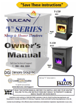
DIMENSIONS
Figure 1
6.00 in
[152.4 mm]
13.70 in
[348 mm]
20.50 in
[520.8 mm]
10.50 in
[266.6 mm]
24.25 in
[615.9 mm]
26.19 in
[665.2 mm]
30.50 in
[774.6 mm]

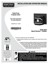
DIMENSIONS - continued
The minimum installation dimensions, of the insert opening, are:
32” (813mm) wide x 22-3/4” (578mm) high x 12-1/4” (311mm) deep.
Figure 2
7

8
OPERATING INSTRUCTIONS
Check and Fill the Fuel Hopper with Pellets:
This Pellet Stove is available as a freestanding unit or as a fi replace insert. There is a different method for fi lling the hopper for each type
of heater:
To check and fi ll the hopper of the freestanding heater, simply lift the hopper door, visually check the hopper and add pellets
when needed.
To check and fi ll the hopper of the insert heater, pull hopper lid forward, visually check the hopper and
add pellets when needed.
CAUTION: DO NOT OVERFILL THE PELLET FUEL HOPPER. AS A SAFETY PRECAUTION, AUGER WILL NOT OPERATE AT ANY
TIME WHEN FUEL HOPPER DOOR IS OPEN.
Pre-start Check-up:
Make sure that all parts of the pellet stove room heater are cool before proceeding. Remove the burn pot and clean out any ash debris.
Be sure to re-install the burn pot in the correct position (see page 8).
The blowers and automatic fuel supply are controlled from a panel located on the right hand side of the stove.
Note: Your Pellet Stove may omit an odor as oil residue from the manufacturing process burns off and the high temperature
paint cures. You can minimize this effect by running a smaller fi re for the fi rst few hours of operation. Avoid placing any items
on the stove top during this period as the stove’s paint could be permanently damaged.
Lighting Instructions:
ATTENTION: Viewing door must be securely latched to ensure proper stove operation. Push door closed and engage latches
in locking holes on door. Press latch handles toward stove body until fully engaged; you will feel the latch engage and hear an
audible click. If door is loose adjust tension control nuts on latches until both latches hold door secure and tight.
When fi rst operating your Pellet Stove, depress the MODE button until the LED indicator above MANUAL lights up. This will engage
MANUAL mode and provide you with full control of the heater’s control board functions and allow you to familiarize yourself with how the
heater works. The heat level for T-STAT mode can only be set when the control is in the Manual Mode.
Starting Up The Pellet Stove Room Heater:
Whenever operating the pellet stove for fi rst time, or if the stove runs out of pellets, it is necessary to prime the auger with pellet fuel. To
do this, Press and Hold the AUGER Button for Approximately 3 Seconds until the AUGER LED illuminates. This procedure will prime the
auger and then automatically initiate the normal ignition cycle.
CAUTION: Do not use this procedure for normal startup. To do so would cause excessive fuel build-up in the burn pot.
For normal startup with pellet fuel in the auger, press and release the On/Off button. The LED indicator light above the On/Off button will
alternately fl ash green then red to indicate that the start-up cycle has begun. The light above the Auger button will fl ash intermittently to
indicate the activation of the auger feeding the pellets into the burn pot. The electric igniter will also be activated at this time. The igniter
takes a few minutes to come up to temperature in order to ignite the pellets in the burn pot. It will normally take between 4 minutes and
8 minutes for pellets to ignite.
NOTE: If pellets do not ignite within 12 minutes the heater will shut down, requiring you to turn on the heater and repeat the
start-up process.
When the pellets have ignited and fl ame has been established, the start-up cycle will end; this procedure takes between 8 and 12 minutes.
If the control is set to Manual Mode, it will now default to the heat level setting the last shutdown time. If the control is set to T-STAT Mode,
the heat output will coincide to the commands from the thermostat.
Auger:
As explained in the starting up step, this button is only served to start up the pellet stove in lieu of the on/off button when there are no
pellets in the auger.
Circulation Air Flow:
Your pellet stove room heater features circulation air fl ow which will change in accordance with the heat setting. Circulation air fl ow will be
at its maximum setting when the heat setting is also at maximum and subsequently will be at its minimum setting when the heat setting is
at minimum. If you desire t
o operate the circulation fan at its maximum setting regardless of heat setting, you may do so by pressing the
FAN button.
Auger Trim:
When operating at Heat Level 1, if the fl ame goes out or the heat output is too high on the minimum heat level setting, use the AUGER
TRIM button to make adjustments. See the AUGER TRIM button description on page 8.
Shutting Down Your Pellet Stove Room Heater:
Turn off the heater by pressing the On/Off button. The stove will enter the shutdown cycle and the pellets will stop feeding into the burn pot
to allow the fuel in the burn pot to be combusted and consumed. During this period, the exhaust blower and circulation fan will continue to
operate until the fl ames are out and the heater has cooled down. When the heater has cooled down to its pre-set level, it will shut down
completely.
CAUTION: NEVER TURN OFF THE HEATER BY UNPLUGGING OR DISCONNECTING ITS ELECTRICAL POWER SOURCE. DOING SO
WILL CAUSE THE HEATER TO SKIP THE PROPER SHUTDOWN CYCLE, CAUSING THE HEATER TO OVERHEAT AND THE POSSIBLE
RELEASE OF SMOKE INTO THE HOUSE.

9
OPERATING INSTRUCTIONS - continued
Control Board Functions:
MODE Button: The MODE button allows you to switch operating mode on your pellet stove room heater.
Depress the MODE button to switch between Manual and T-STAT modes. As you depress the MODE button,
the indicator light above the desired mode will engage. When you engage the Manual mode, you will be
able to manually select the heat settings. If you have installed a remote thermostat for your heater and wish
to have the heater controlled by that thermostat, depress the MODE button to engage T-STAT mode. The
thermostat will control the heat output of the heater alternating between the lowest heat level and the highest
heat level that you have pre-selected.
The T-STAT mode provides the most even heat output, for better
comfort, and to extend the life of the pellet fuel ignition system. Additionally, the constant fl ame serves as a
warning for people and pets to keep away from the heater while it is in operation.
ON/OFF Button: The ON/OFF button is used to turn the heater on and off. Whenever there is power to the
heater, the LED indicator light above the ON/OFF button will be solid red. If the heater is cold prior to start-up,
press and release the ON/OFF button. The LED light above the ON/OFF button will alternately fl ash red and
green to indicate the startup cycle has started. Fuel pellets will start to feed into the burn pot and the pellet fuel
ignition system will be activated. Flames in the burn pot will normally appear between 4 - 8 minutes, and once
the fl ame has been established, the startup cycle will end, this takes between 8-12 minutes. At this point the
LED indicator light above the ON/OFF button will glow solid green. The user will now be able to make heat level
adjustments.
HEAT LEVEL Button: Depress the HEAT LEVEL button to advance the heat level by one level until you reach the
maximum setting; from the maximum level you will decrease one level each time you depress the HEAT LEVEL button.
The circulation fan speed will also increase with the heat level setting. Wait until the startup cycle is complete and the
ON/OFF LED is solid green to set Heat Level. (The HEAT LEVEL LEDs are also used as codes to indicate a malfunc-
tion, please refer to the Safety Features and warning codes section for more information.)
FAN Button: Depressing the FAN button will set the circulation fan speed to high, overriding the automatic fan speed control. The onboard
logic will modulate the fan speed in accordance with the heat level setting. It is recommended that you allow the control to automatically set and
adjust the speed of the fan to obtain optimum effi ciency and minimal fan noise.
AUGER Button: Whenever Operating the Pellet Stove for First Time, or if The Stove Runs Out Of Pellets, it is Necessary to Prime the Auger
with Pellet Fuel. To do this, Press and Hold the AUGER Button for Approximately 3 Seconds until the AUGER LED illuminates. This Procedure
will prime the Auger and then Automatically Initiate the Normal Ignition Cycle.
NOTICE: Do not use this procedure for normal startup. To
do so would cause excessive fuel build-up in the burn pot.
AUGER TRIM Button: This Button is only enabled when operating at Heat Level 1. Depress the AUGER TRIM Button to change
the Auger feed
rate on the minimum heat level to account for the quality of pellet fuel being used. Increasing the Auger feed rate will help keep the fl ames
from extinguishing on the minimum heat level setting. You can also use the AUGER TRIM button to lower heat output on the minimum heat
level setting:
Depress and release the AUGER TRIM button until the heat level 1 and 5 setting lights appear to slightly increase the feed rate on the
minimum heat level.
Depress and release the AUGER TRIM button until the heat level 1 and 4 setting lights appear to slightly reduce the pellet feed rate on the
minimum heat level setting. Use this setting to reduce the heat level output on low.
Depress and release the AUGER TRIM button until only the heat level 1 setting light is on, this is the factory setting and works for most
types of fuel.
Open Door: During normal operation the heater will automatically shut off if the viewing door is opened for more than 30 seconds. This
action causes the heater to go into vacuum error mode. To clear this error and restart the heater, close the door, depress the ON/OFF button
and then follow directions for restarting heater.
Refi lling the Fuel Hopper: For maximum performance do not let the pellet fuel hopper drop below 1/4 full.
Fuel Hopper Lid Safety Switch: When the Fuel Hopper Lid is opened the auger will stop turning to prevent accidental injury.
KEEP PELLET FUEL HOPPER LID CLOSED AT ALL TIMES EXCEPT WHEN REFILLING. DO NOT OVERFILL HOPPER.
Safety Features and warning code:
1. Your heater is equipped with a temperature “high-limit” switch, designed to shutdown the auger in case of an over temperature situation. The
high-limit switch is a thermo snap disc type and must be manually reset in the event of an overheat shutdown. Once the heater has cooled
down, you can reactivate the high-limit switch by depressing the manual reset button located on the high-limit switch.
2. When the High-Limit switch opens, which indicates an overheat failure, the HEAT LEVEL LED’s 3 & 4 will fl ash red.
3. Your heater is equipped with a vacuum switch that automatically shuts down the auger in the event of a exhaust fan malfunction.
4. When a Vacuum Error is sensed, the HEAT LEVEL LED’s 1 & 2 will fl ash red. Check to ensure the glass door is latched properly.
5. When the Low-Limit switch opens, (fi re went out) the HEAT LEVEL LED’s 4 & 5 will fl ash red. First check fuel supply, then check to
ensure Auger is not jammed and fi nally that pellet hopper door is properly closed.
6. When the Pellets in the Burn Pot fail to ignite HEAT LEVEL LED’s 1 & 5 will fl ash red.
NOTE: In the event that the high-limit switch or vacuum switch activates, please contact your dealer to discuss the cause of this
activation and to ensure that your heater continues to operate in a safe manner. Either switch tripping can indicate a problem with
the operation of your heater.
Figure 3

THERMOSTAT INSTALLATION
Optional thermostats are available for use with your pellet stove. A thermostat can help you maintain a constant room
temperature. The thermostat option will require the installation of a millivolt type thermostat.
NOTE: Your thermostat should be installed by an authorized dealer or service person.
Installation of Remote Thermostat:
• Disconnect Pellet Stove Room Heater unit from power supply.
• Open right side panel to gain access to rear of control panel.
• Strip insulation from thermostat wires and connect to the screw terminal on the rear of the control panel (see Figure 4).
If you have installed a remote thermostat for your pellet stove and wish to have the heater controlled by that thermostat,
depress the MODE button to engage T-STAT mode. The thermostat will control the heat output of the heater alternating
between the lowest heat level and the highest heat level that you have pre-selected.
The T-STAT mode provides the most even heat output, for better comfort, and to extend the life of the pellet fuel ignition
system. Additionally, the constant fl ame serves as a warning for people and pets to keep away from the heater while it is
in operation.
10
Figure 4
Connection Terminal for External ermostat
Le : GND
Middle: ermostat
Right: 5V power source

11
CLEARANCES TO COMBUSTIBLES
INSTALL ALL VENTS AT CLEARANCES SPECIFIED BY THE VENT MANUFACTURER!
When your Pellet Stove Room Heater is being installed on a combustible fl oor it is mandatory that a 1/2” (13mm) thick non-
combustible hearth pad be installed under the heater. The non-combustible hearth pad must extend at least 6” beyond the
fuel loading and ash removal openings and at least the depth of the heater plus 6 inches (152mm) out in front of the heater.
This applies to both freestanding heaters and insert heaters.
BACK WALL
Figure 5
Figure 6
Alcove Dimensions
36”
35”
40”
2”
6”
USA 6”
CANADA 8”
FLOOR PROTECTION
USA 6”
CANADA 18”
2”
FLOOR
PROTECTION
USA 6”
CANADA 8”
USA 6”
CANADA 18”

12
INSTALLING YOUR ROOM HEATER
You have already made the important decision of choosing your U.S. Stove Pellet Burning Room Heater; now your next step
is to determine where to install your new pellet stove heater. To get the most effi cient use of re-circulated heat, you should
consider a room that is centrally located within your home. Choose a room that is large and open.
It is Extremely Important to maintain proper clearances from any combustible surfaces or materials in the room where your
heater will be located. You can fi nd proper clearance measurements on page 12 of this manual and on the rating label of
your pellet stove.
The pellet stove can be vented through an exterior wall or into an existing masonry or metal chimney. The chimney must
be lined if it is over 6” (150mm) in diameter or if it has a cross-sectional area of over 28 square inches (711mm2). Venting
can pass through the ceiling and roof if approved pipe is used. Where passage through a wall, or partition of combustible
construction is desired, the installation must conform to CAN/CSA-B365
DO NOT OBTAIN COMBUSTION AIR FROM THE ATTIC, GARAGE OR ANY OTHER UNVENTILATED AREA. YOU MAY
OBTAIN COMBUSTION AIR FROM A VENTILATED CRAWLSPACE.
DO NOT INSTALL A FLUE DAMPER IN THE EXHAUST VENTING SYSTEM OF THIS UNIT.
DO NOT CONNECT THIS UNIT TO A CHIMNEY FLUE SERVING ANOTHER HEATER, FURNACE OR APPLIANCE.
INSTALL VENT AT CLEARANCES SPECIFIED BY THE VENT MANUFACTURER.
ONLY USE APPROVED MATERIAL FOR INSTALLATION, FAILURE TO DO SO MAY RESULT IN PROPERTY DAMAGE,
BODILY INJURY, OR EVEN DEATH.
This appliance is certifi ed for use with listed 3 inch or 4 inch “PL” or “L” pellet venting products as well as Selkirk’s Direct-
Temp Vent system for pellet burning appliances. The use of other components other than stated herein could cause bodily
harm, heater damage, and void your warranty.
HORIZONTAL EXHAUST VENT INSTALLATION
1. Locate your pellet stove in a location which meets the requirements of this manual, but in an area where it does not
interfere with the house framing, wiring, etc.
2. Install a non-combustible hearth pad underneath the pellet stove. This pad should extend at least 6” (152mm) in front
of the unit.
3. Place the pellet stove approximately 15” (381mm) away from the interior wall.
4. Locate the center of the exhaust pipe of your unit. This point should then be extended to the interior wall of your house.
Once you have located the center point, on the interior wall, cut a 7” (175mm) diameter hole through the wall.
5. The next step is to install the wall thimble, refer to the instructions which come with the wall thimble for this step.
6. Install the appropriate length of exhaust vent pipe into the wall thimble. See steps 11 and 12 when determining the cor-
rect length of exhaust vent to use.
7. Outside Fresh Air is Mandatory when installing this pellet stove room heater in airtight homes and mobile
homes. Be sure that the outside air vent has an approved cap on it to prevent rodents from entering. Be sure to install
in location that won’t become blocked with snow, etc.
8. The air intake pipe is equipped with a butterfl y valve that is preset to maximum air intake. For optimum operating ef-
fi ciency you may calibrate the butterfl y valve to provide less intake air. (See Figure 7) Caution: Too much restriction
on the intake air will cause dirtier burn, therefore, will require more frequent cleaning.
9. Connect the exhaust vent pipe to the exhaust outlet of your pellet stove.
10. Secure all vent joint connections with 3 screws. Seal the exhaust vent joint connections with high temperature silicone
sealant.
11. Push the unit straight back to the interior wall, being sure to maintain the minimum clearances to combustibles 6”
(152mm) to the back of the unit. Seal the annular space of the wall thimble and around the vent pipe with high tem-
perature silicone sealant.
12. The exhaust vent pipe must extend at least 12” (300mm) out past the exterior wall. Seal the annular space of the wall
thimble and around the vent pipe with high temperature silicone sealant.
13. Install an approved horizontal termination cap or if necessary install a 90° elbow and appropriate length of vertical vent-
ing. An approved vertical vent cap is recommended.

13
INSTALLING YOUR ROOM HEATER - continued
HORIZONTAL EXHAUST VENT INSTALLATION
Figure 8
Listed Horizontal Cap
Exhaust Vent
Wall Thimble Mfg.
by Pellet Vent Mfg.
Combustion Air Intake
with approved cap
6” (152mm)
Clearance to
Combustibles
Floor Protector
6” (152mm) Clearance
Front
Figure 9
6” (152 mm) Clearance
Wall to Back of Unit
Wall Thimble
Exhaust Vent
45 Elbow
or Listed Termination
Rodent Mesh Cap
Combustion Air
Intake with
approved cap
12” (300mm)
Existing Floor
(Combustible)
Non-Combustible
Floor Protection
6” (152 mm)

14
INSTALLING YOUR ROOM HEATER - continued
FREESTANDING INTERIOR VERTICAL INSTALLATION
1. Locate your Pellet Stove Room Heater in a location which meets the requirements of this manual, but in an area where
it does not interfere with the house framing, wiring, etc.
2. Install a non-combustible hearth pad underneath the pellet stove. This pad should extend at least 6” (152mm) in front
of the unit.
3. Place your Pellet Stove Room Heater on the hearth pad and locate the unit in a manner that will leave the exhaust vent
with a minimum of 3” (75mm) clearance to any combustible wall.
4. When installing the air intake, locate the center of the combustion air intake pipe at the back of your unit. Line up the
center with the same spot on your exterior wall and cut a 2-1/2” (64mm) diameter hole through the wall.
5. Secure all vent joint connections with 3 screws. Seal the exhaust vent joint connections with high temperature silicone
sealant.
6. Install the combustion air intake pipe.
7. Install a tee, with a cleanout, on the exhaust pipe found at the rear of your unit.
8. Install approved vent upward through the ceiling. When you pass through the combustible framing ensure that the ap-
propriate ceiling fi re stop is used. You must maintain a minimum 3” (75mm) clearance to combustibles and keep any
insulation away from the exhaust vent.
9. Extend the exhaust vent through the roof fl ashing and ensure that the vertical cap is approximately 36” (900mm) above
the roof.
Listed Termination
Flashing
36” (900 mm)
3” (75 mm) Clearance
to Combustibles
Use Ceiling Firestop
3” (75mm) Clearance
to Combustibles
3” (75 mm)
Tee with
Cleanout
6” (150 mm)
Combustion Air
Intake with approved cap
Non-Combustible
Floor Protection
Existing Combustible
Floor
Figure 10
6” (150 mm)
Use Ceiling Firestop
3” (75mm) Clearance
to Combustibles

15
INSTALLING YOUR ROOM HEATER - continued
FREESTANDING EXTERIOR VERTICAL INSTALLATION
1. Locate your Pellet Stove Room Heater in a location which meets the requirements of this manual, but in an area where
it does not interfere with the house framing, wiring, etc.
2. Install a non-combustible hearth pad underneath the pellet stove. This pad should extend at least 6” (152mm) in front
of the unit.
3. Place your Pellet Stove Room Heater on the hearth pad and locate the unit in a manner that will leave the exhaust vent
with a minimum of 3” (75mm) clearance to any combustible wall.
4. If installing the optional air intake, locate the center of the combustion air intake pipe at the back of your unit. Line up the
center with the same spot on your exterior wall and cut a 2-1/2” (64mm) diameter hole through the wall.
5. Secure all vent joint connections with 3 screws. Seal the exhaust vent joint connections with high temperature silicone
sealant.
6. Locate the center of the exhaust pipe, at the back of the unit. Line up the center with the same spot on the exterior wall
a cut a 7” (178mm) diameter hole through the wall.
7. Install the wall thimble; (refer to the instructions which come with the wall thimble).
8. Install an approved exhaust vent through the wall; be sure to make sure that 3” (75mm) clearances to combustibles are
maintained.
9. Secure all vent joint connections with 3 screws. Seal the exhaust vent joint connections with high temperature silicone
sealant.
10. Install a Tee with a cleanout on the end of the exhaust pipe and then install approved venting upward from there. Be
sure to install support brackets every 5’ (1525cm) to keep the venting straight and secure.
11. Extend the exhaust vent through the roof fl ashing and ensure that the vertical cap is approximately 36” (900mm) above
the roof.
Figure 11
Listed Termination
Flashing
36” (900 mm)
3” (75 mm)
Clearance
6” (150 mm)
Clearance
Wall Thimble
Tee
w/ Cleanout
Support Bracket
6” (150mm)
Non-Combustible
Floor Protection
Existing Combustible
Floor
Combustion Air Intake
with approved cap

16
INSTALLING YOUR ROOM HEATER - continued
SELKIRK DIRECT-TEMP VENT SYSTEM FOR PELLET STOVE HEATERS
Images courtesy of Selkirk

17
INSTALLING YOUR ROOM HEATER- continued
SELKIRK DIRECT-TEMP VENT SYSTEM FOR PELLET STOVE HEATERS
UP AND OUT HORIZONTAL TERMINATION KIT
FIGURE 12
Images courtesy of Selkirk

18
INSTALLING YOUR ROOM HEATER- continued
SELKIRK DIRECT-TEMP VENT SYSTEM FOR PELLET STOVE HEATERS
STRAIGHT OUT HORIZONTAL TERMINATION KIT
FIGURE 12
Images courtesy of Selkirk

19
INSTALLING YOUR ROOM HEATER - continued
SELKIRK DIRECT-TEMP VENT SYSTEM FOR PELLET STOVE HEATERS
Images courtesy of Selkirk
THROUGH THE ROOF VERTICAL TERMINATION KIT
FIGURE 14

20
MOBILE HOME INSTALLATION
Mobile home installation should be done in accordance with the Manufactured Home and Safety Standard (HUD), CFR 3280,
Part 24. Canadian installations require that the heater must be connected to a 3 or 4 inch, factory-built chimney conforming to
CAN/ULC-S629. See the installation illustrations in this manual for minimum height above the roof. U.S. Stove suggests the use
of Selkirk’s Pellet Venting Products. Refer to their installation instructions for proper installation of the exhaust and combustion
air intake. The chimney installation must allow for removal in case of mobile home transportation, especially outside connec-
tions. You may contact your local building authority or person having jurisdiction on height restrictions.
In order for this unit to be installed in a mobile home the following criteria must be met:
• The unit must be secured to the fl oor using lag bolts in the holes provided in the pedestal base.
• Ensure that the unit is permanently electrically grounded to the chassis of your home.
• All exhaust systems must have a spark arrestor.
IT IS MANDATORY TO TAKE THE COMBUSTION AIR FROM THE OUTSIDE WHEN INSTALLING THIS UNIT IN AIR
TIGHT OR MANUFACTURED/MOBILE HOMES.
CAUTION: THE STRUCTURAL INTEGRITY OF THE MANUFACTURED HOME FLOOR, WALL, AND CEILING/ROOF
MUST BE MAINTAINED. MAKE SURE TO MAINTAIN AN EFFECTIVE VAPOR BARRIER BY SEALING WITH SILICONE
WHERE THE CHIMNEY OR OTHER COMPONENTS PENETRATE TO THE EXTERIOR OF THE STRUCTURE. REFER
TO AND FOLLOW THE CHIMNEY MANUFACTURER’S INSTALLATION INSTRUCTIONS.
WARNING: DO NOT INSTALL IN SLEEPING ROOM.
NOTE: Only the freestanding model is approved for installation into a mobile home.
Figure 15
HEARTH PAD
FLOORING
GROUND WIRE, DIRECTLY
TO METAL CHASSIS
STEEL FRAME
1/4” LAG BOLTS,
SECURELY FASTENED
/